

RCM420
RCM420
RCM420

Create successful ePaper yourself
Turn your PDF publications into a flip-book with our unique Google optimized e-Paper software.
<strong>RCM420</strong><br />
Installation Bulletin / Reference Guide<br />
This document is intended as a reference guide for installing and using a BENDER <strong>RCM420</strong> ground<br />
fault monitor. This document includes installation, setup, and usage instructions. For complete details,<br />
including installation, setup, settings, and troubleshooting, refer to the <strong>RCM420</strong> user manual, document<br />
number TGH1410en. This document is intended as a supplement and not a replacement to the<br />
complete user manual.<br />
Only qualified maintenance personnel shall operate or service this equipment. These instructions<br />
should not be viewed as sufficient for those who are not otherwise qualified to operate or service this<br />
equipment. This document is intended to provide accurate information only. No responsibility is assumed<br />
by BENDER for any consequences arising from use of this document.<br />
Installation<br />
Mounting<br />
<strong>RCM420</strong> series devices may be DIN rail mounted, or screw mounted using the black clips located<br />
on the top and bottom of the device. Screw mounting requires an extra black clip (article<br />
number B98060008, sold separately).<br />
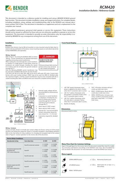
Front Panel Display<br />
1 2 3<br />
Wiring - General<br />
Refer to figure 1 for wiring the <strong>RCM420</strong>. Refer to section<br />
“Wiring - Current Transformers” for detailed information<br />
regarding connecting current transformers.<br />
When routing the circuit through the current transformer,<br />
whether it is single-phase or three-phase, ensure all<br />
conductors are routed through, including the neutral<br />
if it is being used. Do not place the ground conductor<br />
through the CT.<br />
Only the following BENDER current transformers may<br />
be used with an <strong>RCM420</strong>: W0-S20, W1-S35, W2-S70, W3-<br />
! DANGER<br />
HAZARD OF ELECTRIC SHOCK,<br />
EXPLOSION, OR ARC FLASH<br />
• Disconnect all power before servicing.<br />
• Observe all local, state, and national<br />
codes, standards, and regulations.<br />
S105, W4-S140, W5-S210, W20, W35, W60, W120, W210, WR series, WS series. Current transformers<br />
with a part number ending in “8000” may not be used. Use AWG 22, shielded cable.<br />
The maximum length is 130 feet. Current transformers may be screw mounted with the included<br />
mounting feet. Refer to <strong>RCM420</strong> series user manual for complete technical details.<br />
4<br />
5 6 7<br />
Figure 2 - <strong>RCM420</strong> front display<br />
5<br />
Load<br />
3<br />
4<br />
2<br />
6<br />
1<br />
1. External supply voltage; 6A fuse<br />
recommended for internal device<br />
protection<br />
2. Connection to current transformer.<br />
All phases, including the neutral<br />
if it is being used, must be<br />
routed through the CT. Do not<br />
route the ground conductor<br />
through the CT.<br />
3. Alarm relay K1: SPDT contact<br />
4. Alarm relay K2: SPDT contact<br />
5. External test / reset terminal (N/O<br />
contact; momuntary closure for<br />
reset, closure for > 1.5 s for test)<br />
6. Connection required for shielded<br />
cable<br />
1. LED “ON” (green): Illuminates when<br />
power is applied to the device. Flashes<br />
when the CT connection alarm is active.<br />
2. LED “AL1” (yellow): Illuminates when<br />
the prealarm is activated. Flashes when<br />
the CT connection alarm is active.<br />
3. LED “AL2” (yellow): Illuminates when<br />
the main alarm is activated. Flashes<br />
when the CT connection alarm is active.<br />
4. Backlit LCD display<br />
Dimensions<br />
Dimensions listed in inches.<br />
2.78”<br />
1.87”<br />
1.22”<br />
5. TEST / UP button: Activates self-test /<br />
scrolls up inside main menu.<br />
6. RESET / DOWN button: Resets device /<br />
scrolls down inside main menu.<br />
7. MENU / ENTER button: Activates main<br />
menu / Confirms (momuntary push) or<br />
goes back a step (held > 1.5 s) inside<br />
main menu.<br />
1.42”<br />
Figure 1 - <strong>RCM420</strong> wiring diagram<br />
Wiring - Contacts<br />
Using a normally closed or normally open contact utilizes two factors: wiring out of the proper<br />
terminal, and setting the respective contact to normally energized or deenergized operation.<br />
Refer to the chart below for relay conditions. For changing the energized state of the contact,<br />
refer to “Figure 8 - Contact operation” on the reverse side of this document.<br />
2.66”<br />
1.77”<br />
3.54”<br />
Device Relay Conditions<br />
Relay Operation Setting Device Alarm State K1 STATE K2 STATE<br />
Normally deenergized mode (N/D)<br />
Non-failsafe mode<br />
“N/O” in device settings menu<br />
Normally energized mode (N/E)<br />
Failsafe mode<br />
“N/C” in device settings menu<br />
Power ON, normal state (no alarms)<br />
Power OFF<br />
Power ON, alarm state<br />
Power ON, normal state (no alarms)<br />
Power OFF<br />
Power ON, alarm state<br />
11-12 CLOSED<br />
11-14 OPEN<br />
11-12 CLOSED<br />
11-14 OPEN<br />
11-12 OPEN<br />
11-14 CLOSED<br />
11-12 OPEN<br />
11-14 CLOSED<br />
11-12 CLOSED<br />
11-14 OPEN<br />
11-12 CLOSED<br />
11-14 OPEN<br />
21-22 CLOSED<br />
21-24 OPEN<br />
21-22 CLOSED<br />
21-24 OPEN<br />
21-22 OPEN<br />
21-24 CLOSED<br />
21-22 OPEN<br />
21-24 CLOSED<br />
21-22 CLOSED<br />
21-24 OPEN<br />
21-22 CLOSED<br />
21-24 OPEN<br />
Menu Flow Chart for Common Settings<br />
Figure 4 through figure 8 on the reverse side of this document contain flow charts for modifying<br />
commonly used features and settings in the <strong>RCM420</strong>’s main menu. Not all available features<br />
are listed in this document. For more information, consult the <strong>RCM420</strong> user manual.<br />
Menu Legend<br />
R<br />
T<br />
DOWN ARROW button<br />
UP ARROW button<br />
MENU / ENTER button<br />
< 1.5 s<br />
> 1.5 s<br />
Momuntary button push<br />
Hold button for at least 1.5 s,<br />
then release<br />
Bender Inc. • 800.356.4266 / 610.383.9200 • info@bender.org • www.bender.org Document NAE1048030 • 09.2011 • © Bender Inc. • Page 1/1 • Side 1/2
<strong>RCM420</strong><br />
Installation Bulletin / Reference Guide<br />
Figure 4 - Setting main alarm trip value<br />
Figure 7 - Latching behavior (fault memory)<br />
Changing this setting to “ON” will cause the <strong>RCM420</strong> to latch in the event of an alarm, and<br />
require a manual reset if the alarm clears. Changing this setting to “OFF” will cause the <strong>RCM420</strong><br />
to automatically reset if the alarm clears.<br />
> 1.5 sec<br />
< 1.5 sec<br />
> 1.5 sec<br />
< 1.5 sec<br />
> 1.5 sec<br />
R<br />
Press Once<br />
< 1.5 sec<br />
< 1.5 sec<br />
> 1.5 sec<br />
> 1.5 sec<br />
< 1.5 sec<br />
T<br />
R<br />
Set-Point Adjustment<br />
10 mA to 10 A<br />
= Flashing Symbol<br />
Figure 5 - Setting prealarm trip value<br />
< 1.5 sec<br />
> 1.5 sec<br />
T R<br />
Fault Memory<br />
ON/OFF Select<br />
= Flashing Symbol<br />
> 1.5 sec<br />
< 1.5 sec<br />
< 1.5 sec<br />
> 1.5 sec<br />
Figure 8 - Contact operation<br />
Use this option to change the behavior of the contacts between normally deenergized (nonfailsafe)<br />
mode and normally energized (failsafe) mode. The two SPDT contacts may be changed<br />
individually. Note that the <strong>RCM420</strong> labels normally deenergized operation as “N/O” and normally<br />
energized operation as “N/C”; utilzing a normally open or normally closed contact only<br />
depends on which contact output is wired.<br />
R<br />
Press Once<br />
> 1.5 sec<br />
> 1.5 sec<br />
T R<br />
Failsafe<br />
ON/OFF Select<br />
< 1.5 sec<br />
R<br />
Press Once<br />
< 1.5 sec<br />
T R = Flashing Symbol<br />
% Adjustment<br />
50 to 100% of Main Alarm<br />
Figure 6 - Changing Time Delays<br />
Four separate time delays are available:<br />
< 1.5 sec<br />
> 1.5 sec<br />
• t on1<br />
- Response delay, prewarning<br />
• t on2<br />
- Response delay, main alarm<br />
• t - Startup delay<br />
• t off<br />
- Delay on release<br />
R<br />
Press Once<br />
> 1.5 sec<br />
< 1.5 sec<br />
= Flashing Symbol<br />
> 1.5 sec<br />
T<br />
R<br />
ton1 Adjustment<br />
0...10 seconds<br />
R<br />
Press Twice<br />
< 1.5 sec<br />
< 1.5 sec<br />
> 1.5 sec<br />
R<br />
Press:<br />
1 x for ton2<br />
> 1.5 sec<br />
2 x for t<br />
0...10 sec<br />
3 x for toff<br />
0...99 sec<br />
OR<br />
= Flashing Symbol<br />
< 1.5 sec<br />
Bender Inc. • 800.356.4266 / 610.383.9200 • info@bender.org • www.bender.org Document NAE1048030 • 09.2011 • © Bender Inc. • Page 1/1 • Side 2/2


