

COM462RTU - Bender
COM462RTU - Bender
COM462RTU - Bender

You also want an ePaper? Increase the reach of your titles
YUMPU automatically turns print PDFs into web optimized ePapers that Google loves.
T M<br />
5<br />
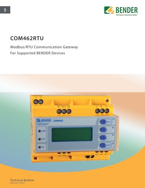
<strong>COM462RTU</strong><br />
Modbus/RTU Communication Gateway<br />
For Supported BENDER Devices<br />
Technical Bulletin<br />
NAE4122520 / 08.2013
Modbus/RTU Communication Gateway<br />
<strong>COM462RTU</strong><br />
Communication Gateway<br />
For Supported BENDER Devices<br />
Description<br />
The <strong>COM462RTU</strong> is a Modbus/RTU communication gateway for compatible BENDER devices.<br />
Up to 150 compatible BENDER devices may be accessed from a single <strong>COM462RTU</strong>.<br />
The <strong>COM462RTU</strong> acts as a slave device on standard Modbus/RTU networks. A simple<br />
address mapping system allows for simple programming to access real-time information of<br />
connected BENDER equipment, including measured values.<br />
<strong>COM462RTU</strong><br />
Features<br />
• Communication gateway between compatible<br />
BENDER devices and Modbus/<br />
RTU communication systems<br />
• Up to 150 BENDER devices connected to<br />
a single <strong>COM462RTU</strong><br />
• Communication from Modbus/RTU master<br />
to a single device for multiple<br />
BENDER devices connected across RS-<br />
485<br />
• Slave on Modbus/RTU network<br />
• Real-time system information including<br />
measured values accessable from<br />
Modbus/RTU system master<br />
Supported BENDER devices<br />
• IRDH275 / IRDH375 / IRDH575 “B” Series Ground Fault Detectors<br />
• RCMS460 / RCMS490 Series Ground Fault Monitors<br />
• LIM2010 Line Isolation Monitor<br />
• EDS460 / EDS490 / EDS461 / EDS491 Series Ground Fault Location Modules<br />
• RCMA421H / RCMA426H “DCB” Series GFCI Modules<br />
• MK2430 / MK800 Series Remote Indicators<br />
Approvals<br />
Ordering Information<br />
AC<br />
76 - 250 V (42 - 460 Hz)<br />
(Draw 10 - 35 mA)<br />
1)<br />
Absolute values<br />
Supply voltage U S<br />
1)<br />
DC<br />
Power consumption Type Ordering No.<br />
76 - 250 V (Draw 6 - 21 mA) 3.5 - 40 VA <strong>COM462RTU</strong> B 9506 1022<br />
2
Operating elements<br />
Wiring diagram<br />
COMTRAXX®<br />
3<br />
2<br />
ALARM<br />
COM<br />
COM462<br />
8<br />
4<br />
5<br />
6<br />
ESC<br />
INFO<br />
U S<br />
6 A 6 A<br />
A1 A2<br />
1<br />
1<br />
ON<br />
7<br />
MENU<br />
A1 A2<br />
1 - "ON“ LED, lights when supply voltage is applied<br />
INFO<br />
ESC<br />
2 - "COM“ LED, lights when the gateway is responding to<br />
BENDER RS-485 requests<br />
ALARM<br />
3 - "ALARM" LED, lights when an internal device error occurs<br />
COM<br />
4 - "INFO" button, to query the <strong>COM462RTU</strong> for device-specific<br />
information<br />
ON<br />
MENU<br />
ESC Exits the menu function without changing parameters<br />
5 - " " button: to move up in the menu, to increase values<br />
6 - " " button: to move down in the menu, to decrease values<br />
4<br />
A<br />
AMB BMB<br />
B<br />
5<br />
(AMB, BMB)<br />
7 - "MENU" button for starting and exiting the menu<br />
" " button to confirm parameter change<br />
8 - LCD display<br />
AMB<br />
2 3<br />
BMB<br />
BMS-Bus<br />
RS-485<br />
Modbus/RTU<br />
RS-485<br />
Dimensions<br />
Dimensions in inches (mm)<br />
2.9”<br />
(74)<br />
1.9” (47.5)<br />
1.2” (31)<br />
4.25” (108)<br />
1 - Connection to the supply voltage<br />
For UL and CSA applications, 5 A fuses are mandatory.<br />
2 - Connection to BENDER RS-485 bus<br />
3 - Connection to Modbus/RTU bus<br />
4 - Switch for BENDER RS-485 bus termination. When the device<br />
is installed at the end of the bus, set the terminating switch to<br />
"on".<br />
5 - Switch for Modbus/RTU bus termination. When the device is<br />
installed at the end of the bus, set the terminating switch to<br />
"on"<br />
2.7” (67.5)<br />
1.8” (45)<br />
3” (77)<br />
3.5” (90)<br />
Ø 0.18”<br />
(4.5) 3.9” (98)<br />
3
Technical data<br />
Insulation coordination acc. to IEC 60664-1<br />
Rated insulation voltage<br />
Rated impulse voltage/pollution degree <br />
AC 250 V<br />
4 kV/3<br />
Supply voltage<br />
Supply voltage U S <br />
see ordering information<br />
Frequency range U S <br />
see ordering information<br />
Power consumption see ordering information<br />
LED indicators<br />
ALARM internal device error<br />
COM data traffic BMS bus<br />
ON operation indicator<br />
Interfaces<br />
BMS bus, internal:<br />
Interface/protocol RS-485/BMS bus, internal<br />
Operating mode master/slave (slave)*<br />
Baud rate BMS internal 9.6 kbit/s<br />
Cable length ≤ 1200 m<br />
Cable (twisted pair, shielded, shield connected to PE on one side) recommended: J-Y(St)Y 2x0.8<br />
Connection, BMS internal terminals A, B<br />
Terminating resistor 120 Ω (0.25 W)<br />
Device address, BMS bus internal 1…99 (2)*<br />
Modbus/RTU:<br />
Interface/protocolRS-485/Modbus/RTU<br />
Operating mode slave<br />
Baud rate Modbus/RTU 9.6…57.6 kbit/s<br />
Cable length ≤ 1200 m<br />
Cable (twisted pair, shielded, shield connected to PE on one side) recommended: J-Y(St)Y 2x0.8<br />
Connection, Modbus/RTU terminals D+, D<br />
Terminating resistor 120 Ω (0.25 W)<br />
Device address, Modbus/RTU 2…247 (2)*<br />
Environment/EMC<br />
EMC EN 61326-1<br />
Classification of climatic conditions acc. to IEC 60721:<br />
Stationary use 3K5<br />
Transport 2K3<br />
Long-term storage 1K4<br />
Operating temperature -10…+55 °C<br />
Classification of mechanical conditions acc. to IEC 60721:<br />
Stationary use 3M4<br />
Transport 2M2<br />
Long-term storage 1M3<br />
Connection<br />
Connection<br />
screw-type terminals<br />
Connection properties:<br />
rigid/flexible 0.2…4/0.2…2.5 mm² (AWG 24…12)<br />
Multi-conductor connection (2 conductors with the same cross section):<br />
rigid/flexible 0.2…1.5 0.2…1.5 mm²<br />
Stripping length 8…9 mm<br />
Tightening torque 0.5…0.6 Nm<br />
Other<br />
Operating mode<br />
continuous operation<br />
Mounting display oriented<br />
Degree of protection, internal components (IEC 60529) IP30<br />
Degree of protection, terminals (IEC 60529) IP20<br />
Type of enclosure<br />
X460<br />
Screw mounting<br />
2 x M4<br />
DIN rail mounting acc. to IEC 60715<br />
Flammability class<br />
UL94V-0<br />
Software version D402 V1.0x<br />
Weight <br />
≤ 310 g<br />
( )* = factory setting<br />
T M<br />
USA • Coatesville, PA<br />
Toll-Free: 800-356-4266 • Main: 610-383-9200<br />
Fax: 610-383-7100 • E-mail: info@bender.org<br />
bender.org • bender.org/mobile<br />
Canada • Mississauga, ON<br />
Toll-Free: 800-243-2438 • Main: 905-602-9990<br />
Fax: 905-602-9960 • E-mail: info@bender-ca.com


