

ISOLATED POWER CENTERS
ISOLATED POWER CENTERS
ISOLATED POWER CENTERS

You also want an ePaper? Increase the reach of your titles
YUMPU automatically turns print PDFs into web optimized ePapers that Google loves.
Medical Division of Bender Inc.<br />
<strong>ISOLATED</strong> <strong>POWER</strong> <strong>CENTERS</strong><br />
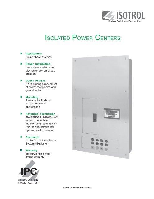
Applications<br />
Single phase systems<br />
Power Distribution<br />
Loadcenter available for<br />
plug-on or bolt-on circuit<br />
breakers<br />
Outlet Devices<br />
Up to 8 gang arrangement<br />
of power receptacles and<br />
ground jacks<br />
Mounting<br />
Available for flush or<br />
surface mounted<br />
applications<br />
Advanced Technology<br />
The BENDER LIM2000plus TM<br />
series Line Isolation<br />
Monitor(LIM) features selftest,<br />
self-calibration and<br />
optional load monitoring<br />
Standards<br />
UL 1047 - Isolated Power<br />
Systems Equipment<br />
Warranty<br />
Industry's first 5 year<br />
limited warranty<br />
IPC<br />
<strong>ISOLATED</strong><br />
<strong>POWER</strong> CENTER<br />
COMMITTED TO EXCELLENCE
Introduction<br />
ISOTROL Type IPC Isolated Power Centers have been designed<br />
to provide isolated power to electrical circuits installed within<br />
operating rooms and other electrically susceptible patient care<br />
areas. Designed in strict compliance with Underwriters<br />
Laboratories Standards UL1047, UL1022 and UL50, the IPC<br />
offers the most current technology for all isolated power<br />
distribution requirements.<br />
General<br />
The Type IPC typically includes a single phase transformer, a<br />
BENDER Line Isolation Monitor (LIM), a reference ground bus,<br />
a primary circuit breaker, branch circuit breakers, Hospital<br />
Grade power receptacles and Hospital Grade ground jacks.<br />
The maximum number of branch circuit breakers is limited to<br />
sixteen (16) plug-on or twelve (12) bolt-on.<br />
Backbox<br />
All backboxes are fabricated from 14GA galvanized steel.<br />
Surface mounted enclosures are finished with a coat of<br />
hospital ivory, epoxy enamel. Outline drawings shown on the<br />
following pages of this brochure provide additional dimensional<br />
and construction details.<br />
Front Trim<br />
Manufactured from 14GA Type 304 Stainless Steel with a #4<br />
brushed finish, the front trim contains a door with hidden<br />
hinges and a flush mounted key lock that covers the load<br />
center. The front trim for flush mounted units extends 1" on all<br />
sides of the backbox. For surface mounted units, the front trim<br />
shall exactly match the dimensions of the backbox.<br />
Isolation Transformer<br />
Isolation transformers are available with various primary and<br />
secondary single phase voltages. The transformer ratings are<br />
given on the isolation transformer data sheet found in ISOTROL's<br />
full catalog or by request.<br />
Line Isolation Monitor (LIM)<br />
The BENDER LIM2000plus TM series Line Isolation Monitor<br />
provides a digital / analog display. The LIM is available in single<br />
or three phase models with readout and response values of<br />
2 or 5mA. The LIM2000plus TM has a patented measuring<br />
principle and is capable of detecting all combinations of<br />
capacitive and resistive faults, including balanced, unbalanced<br />
and hybrid faults. A self-test and calibration function is also<br />
featured. The LIM2000plus TM series LIM contributes less than<br />
35µA to the Total Hazard Current (THC). Available options<br />
include load monitoring and RS485 communication. For<br />
further information see the LIM2000plus TM series data sheet.<br />
Line Isolation Monitor<br />
LIM2000plus TM<br />
Loadcenter<br />
The loadcenter is an integral part of the IPC. Included is a<br />
primary circuit breaker which provides protection for the<br />
isolation transformer. All Isolated Power Centers can<br />
accommodate either plug-on or bolt-on circuit breakers.<br />
Power Receptacles & Ground Jacks<br />
The Type IPC provides an eight gang section for Hospital<br />
Grade power receptacles and Hospital Grade ground jacks.<br />
The Hospital Grade power receptacles are available in either<br />
straight-blade (single or duplex) or twist-to-lock style. Each<br />
gang can accommodate one duplex or single power receptacle<br />
and one ground jack or two ground jacks.<br />
Reference Ground Bus<br />
The Type IPC Isolated Power Center is provided with a twenty<br />
(20) point reference ground bus to satisfy equipotential<br />
grounding requirements and for connection to master ground<br />
modules and ground jacks in patient ground modules and<br />
receptacle ground modules. Other ground bus configurations<br />
available.<br />
Support and Services<br />
On-site installation inspection and certification services<br />
System design assistance provided upon request<br />
Technical support hotline: (800) 833-6834<br />
IPC - 2
BENDER<br />
TOTAL<br />
HAZARD<br />
CURRENT<br />
SAFE<br />
TEST<br />
TRANSFORMER<br />
LOAD<br />
HAZARD<br />
mA<br />
MUTE<br />
mA<br />
>80% LIM2000plus<br />
Outline Drawing for IPC<br />
Single Phase 3 to10kVA<br />
w<br />
d<br />
1.000"<br />
PLAN<br />
W<br />
A<br />
d<br />
1.000"<br />
14<br />
11<br />
H<br />
9<br />
15<br />
5<br />
6<br />
3<br />
h<br />
12<br />
%<br />
mA<br />
16<br />
7<br />
4<br />
8<br />
10<br />
17<br />
20<br />
13<br />
18<br />
FRONT<br />
A<br />
19<br />
1<br />
2<br />
VIEW A - A<br />
BACKBOX<br />
DESIGNATION<br />
TRANSFORMER<br />
kVA SIZE<br />
h<br />
w<br />
DIMENSION<br />
d<br />
H<br />
W<br />
B 3, 5, 7.5, 10 41" 24" 8" 43" 26"<br />
*CALL FACTORY FOR OTHER CONFIGURATIONS<br />
1 Stainless Steel Front Trim 11 Main Circuit Breaker, 2P<br />
2 Backbox, Galvanized Steel 12 Branch Circuit Breaker, 2P<br />
3 Backplate, Galvanized Steel 13 Loadcenter<br />
4 Backplate Mounting Bracket 14 Isolation Transformer, 1Ph<br />
5 Transformer Shelf 15 Line Isolation Monitor, 1Ph<br />
6 Transformer Shelf Mounting Bracket 16 LIM Connector Plate<br />
7 Circuit Breaker Deadfront 17 Ground Bus<br />
8 Stainless Steel Door w/Lock 18 Hospital Grade Power Receptacles<br />
9 LIM Fuses 19 Hospital Grade Ground Jacks<br />
10 LIM Circuit Breaker, 2P (Optional) 20 Receptacle Hat Section<br />
IPC - 3
TO TAL<br />
HAZARD<br />
CURRENT<br />
SAFE<br />
TEST<br />
TRANSFORMER<br />
LOAD<br />
mA<br />
mA<br />
>80%<br />
HAZARD<br />
MUTE<br />
Wiring Diagram for IPC<br />
Single Phase 3 to 10kVA<br />
T1<br />
4<br />
H2<br />
X1<br />
INCOMING<br />
<strong>POWER</strong><br />
7<br />
H1<br />
PANEL<br />
GROUND<br />
X2<br />
mA<br />
8<br />
3<br />
BENDER<br />
%<br />
LIM2000plus<br />
5<br />
1<br />
3<br />
5<br />
7<br />
9<br />
11<br />
L1<br />
L2<br />
6<br />
2<br />
4<br />
6<br />
8<br />
10<br />
12<br />
1<br />
2<br />
OR<br />
9<br />
TO SYSTEM<br />
GROUND<br />
L1<br />
L2<br />
12V DC Com<br />
M *<br />
TO REMOTE<br />
M + INDICATOR<br />
RI1 SERIES<br />
K1/NC MK2000<br />
K1/COM (If Required)<br />
K1/NO<br />
SAFE<br />
METERED<br />
HAZARD *<br />
REMOTE ONLY<br />
RI2<br />
GND2<br />
LIM GND<br />
TEST/L3<br />
PANEL<br />
GROUND<br />
PANEL<br />
GROUND<br />
10<br />
11<br />
12<br />
1 LIM Fuses<br />
2 LIM Fuses Disconnect<br />
3 Loadcenter<br />
4 Main Circuit Breaker, 2P<br />
5 Branch Circuit Breaker, 2P<br />
6 LIM Circuit Breaker, 2P (Optional)<br />
7 Isolation Transformer, 1Ph<br />
8 Line Isolation Monitor (LIM), 1Ph<br />
9 LIM Connector Plate<br />
10 Ground Bus<br />
11 Hospital Grade Power Receptacles<br />
12 Hospital Grade Ground Jacks<br />
IPC - 4
Selection Guide for Isolated Power Centers (Type IPC)<br />
When selecting the Isolated Power Center for your application, use the Product Code below. If you have any<br />
questions or need further assistance, please call us using our toll-free number: (800) 833-6834.<br />
Code A - Basic Designation<br />
IPC: Isolated Power Center<br />
Code B - Transformer Power Rating<br />
3: 3kVA 5: 5kVA 7: 7.5kVA 10: 10kVA X: Special kVA<br />
Code C - Transformer Primary Voltage<br />
A: 120V B: 208V C: 240V D: 277V<br />
E: 480V G: 220V H: 110V X: Special Voltage<br />
Code D - Transformer Secondary Voltage<br />
A: 120V B: 208V C: 240V G: 220V H: 110V X: Special Voltage<br />
Code E - Phase<br />
1: 1 Phase<br />
Code F - Loadcenter Manufacturer and Size<br />
C1: Cutler Hammer 10 Positions Bolt-On only CX: Cutler Hammer<br />
12 Positions Plug-On only Lug-to-Lug Circuit Breakers (No Loadcenter)<br />
G1: General Electric 14 Positions Plug-On only GX: General Electric<br />
G2: General Electric 16 Positions Plug-On only Lug-to-Lug Circuit Breakers (No Loadcenter)<br />
S1: SquareD 12 Positions Plug-On & Bolt-On SX: Square D<br />
Code G - Quantity of Branch Circuit Breakers<br />
Lug-to-Lug Circuit Breakers (No Loadcenter)<br />
Code H - Circuit Breaker Type<br />
P: Plug-on B: Bolt-on L: Lug-to-lug<br />
Code I - Number of Circuit Breaker Openings in Deadfront (Must be less than or equal to Loadcenter positons)<br />
Code J - Quantity of Ground Jacks<br />
Maximum of 8 Ground Jacks<br />
Code K - Quantity of Power Receptacles<br />
Maximum of 8 Power receptacles<br />
Code L - Type of Power Receptacle<br />
The designation S1, S2, SM, D1, D2, DM, T1, T2 or TM<br />
SINGLE<br />
DUPLEX<br />
TWIST-TO-LOCK<br />
Type<br />
S1<br />
SM<br />
D1<br />
DM<br />
T1<br />
TM<br />
Voltage<br />
125V<br />
125V<br />
125V<br />
Hubbell<br />
Style#<br />
Color<br />
HBL8310R<br />
Red<br />
OTHER<br />
HBL8300HR<br />
Red<br />
OTHER<br />
HBL23000HG<br />
Black<br />
OTHER<br />
NEMA#<br />
5-20R<br />
5-20R<br />
n/a<br />
Note: - Above receptacles are 2P/3W, 20A, single phase<br />
- If the IPC contains several types of receptacles, the product code will be expanded by adding multiple blocks of<br />
Codes K and L.<br />
- Other receptacles are available<br />
Code M - Backbox Sizes (Height x Width x Depth)<br />
B: 41" x 24" x 8" X: Special<br />
Code N - Type of Mounting<br />
F: Flush S: Surface<br />
Call the factory for additional equipment or custom requirements<br />
Example for ISOTROL type IPC Product Code<br />
IPC - 7 B A 1 - C 1 /12 P 12 - 4 - 6 D1- B F<br />
Code A Code B Code C Code D Code E Code F Code G Code H Code I Code J Code K Code L Code M Code N<br />
IPC - 5
Suggested Specification for ISOTROL<br />
Type IPC Isolated Power Centers<br />
Furnish and install ISOTROL Type IPC Isolated Power Center<br />
in the locations shown on the architectural / electrical drawings.<br />
The IPC shall be UL Listed and labeled as an assembly. The<br />
Type IPC shall consist of the following:<br />
Backbox<br />
Shall be flush or surface mounted as required, and shall be<br />
fabricated from 14GA galvanized steel. Surface mounted<br />
enclosures shall be finished with a coat of hospital ivory, epoxy<br />
enamel.<br />
Front Trim<br />
Shall be fabricated from 14GA Type 304 Stainless Steel with<br />
#4 brushed finish. The circuit breaker section shall be<br />
accessible from a door, with hidden hinges, that is flush with<br />
the front trim. The door shall contain a flush lock that can be<br />
opened without a key when unlocked; all IPCs shall be keyed<br />
alike. The front trim shall contain a cut out for the Line Isolation<br />
Monitor (LIM) which shall remain visible at all times. The front<br />
trim for flush mounted units extends 1" on all sides of the<br />
backbox. For surface mounted units, the front trim shall exactly<br />
match the dimensions of the backbox. The front trim shall be<br />
attached to the backbox by a minimum of ten (10) #10-32 x 1"<br />
Stainless Steel Oval Head Phillips machine screws and ten<br />
(10) #10 Stainless Steel finishing washers.<br />
Isolation Transformer<br />
Shall be single phase, 50Hz or 60Hz, with primary and<br />
secondary voltages as indicated on the drawings. The<br />
transformer shall be manufactured using class H-rated<br />
insulation. It shall have an electrostatic shield between the<br />
primary and secondary windings which shall be grounded to<br />
the enclosure. The transformer core shall be a stacked design,<br />
securely clamped. Core and coil shall be vacuum impregnated,<br />
with a final wrap of insulating material. The core and coils<br />
shall be isolated from the enclosure by means of isolation<br />
mounts. The weight of the transformer shall not be supported<br />
by shear connections.<br />
Total leakage current to ground from transformer secondary<br />
winding shall be in compliance with UL1047, Tables 30.1 and<br />
30.2. Maximum sound level of transformer: 25dB for 5kVA units<br />
or less, 30dB for 7.5kVA units, and 35db for 10kVA units.<br />
Temperature rise limited 115 degees C above ambient under<br />
full load conditions. Transformer shall be UL Listed or<br />
Recognized as a component, for the voltages, amperage, and<br />
kVA rating required.<br />
Line Isolation Monitor<br />
Shall be a BENDER LIM2000plus TM series Line Isolation Monitor<br />
with a solid state modular assembly utilizing the dynamic<br />
principle of constantly monitoring the impedance between<br />
each circuit conductor and ground and shall<br />
provide visual and audible indications of a first fault condition.<br />
The LIM shall be capable of detecting all combinations of<br />
capacitive and resistive faults, including balanced, unbalanced<br />
and hybrid faults. The total hazard current shall be set at the<br />
factory to either 2 mA or 5 mA, and shall be field adjustable to<br />
either milliampere.<br />
The LIM shall contain a continuous display (digital / analog), an<br />
audible alarm device which shall sound in the event of a hazard<br />
condition, and a visual indication of the system status. A green<br />
LED shall indicate "SAFE" status, a red LED shall indicate<br />
"HAZARD" status, and an amber LED shall indicate that the<br />
audible alarm feature is in the "MUTE" mode. A "TEST" button<br />
shall be provided so the functions of the LIM can be tested by<br />
hospital personnel. The digital display, indicating LEDs, and<br />
"TEST" button shall all be flush with the face of the LIM and<br />
shall be protected by a rugged Lexan front foil. Remote indicator<br />
connections shall be provided.<br />
The LIM shall contain overload protection with an automatic<br />
reset feature. It shall be possible to order the LIM with an optional<br />
RS485 communication port and load monitoring. The LIM shall<br />
be UL Recognized as a component.<br />
Primary Circuit Breaker<br />
Shall be two-pole sized in accordance with NFPA 70 (NEC)<br />
based on the transformer primary voltage and kVA rating as<br />
shown on the contract documents, and shall be full size, thermal<br />
magnetic type, minimum 10kAIC.<br />
Secondary Branch Breakers<br />
Shall be two-pole, ampacities, and quantities based on the<br />
contract drawings. Sized in accordance with NFPA 70 (NEC)<br />
and UL1047 Standards. Shall be full size and thermal magnetic<br />
type with a minimum 10kAIC.<br />
Reference Ground Bus<br />
Shall contain a minimum of one (1) #4-2/0 main lug and<br />
nineteen (19) #14-4 grounding lugs.<br />
Power Receptacles<br />
Shall be UL Listed/Recognized Hospital Grade specification and/<br />
or NEMA configuration with ampacity, voltage, color and<br />
quantities in accordance with contract drawings.<br />
Ground Jacks<br />
Shall be UL Listed for hospital application as well as green in<br />
color and provide in quantities in accordance with the contract<br />
drawings.<br />
Specifications and other data subject to change without notice.<br />
Our Address<br />
BENDER / ISOTROL<br />
700 Fox Chase<br />
Coatesville, PA 19320<br />
Phone: 800-833-6834<br />
610-383-9655<br />
Fax: 610-383-7100<br />
E-mail: isotrol@bender.org IPC - 6<br />
Medical Division of Bender Inc.<br />
Rev 4 - 2009' LST


