

View PDF
View PDF
View PDF

You also want an ePaper? Increase the reach of your titles
YUMPU automatically turns print PDFs into web optimized ePapers that Google loves.
T M<br />
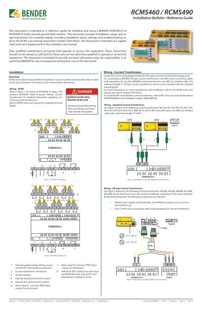
RCMS460 / RCMS490<br />
Installation Bulletin / Reference Guide<br />
This document is intended as a reference guide for installing and using a BENDER RCMS460-D or<br />
RCMS490-D multi-channel ground fault monitor. This document includes installation, setup, and usage<br />
instructions. For complete details, including installation, setup, settings, and troubleshooting, refer<br />
to the RCMS user manual, document number TGH1393en. This document is intended as a supplement<br />
and not a replacement to the complete user manual.<br />
Only qualified maintenance personnel shall operate or service this equipment. These instructions<br />
should not be viewed as sufficient for those who are not otherwise qualified to operate or service this<br />
equipment. This document is intended to provide accurate information only. No responsibility is assumed<br />
by BENDER for any consequences arising from use of this document.<br />
Installation<br />
Mounting<br />
RCMS series devices may be DIN rail mounted, or screw mounted using the black clips located<br />
on the top and bottom of the device. See reverse side for dimensions.<br />
Wiring - RCMS<br />
Refer to figure 1 for wiring an RCMS460, or figure 2 for<br />
wiring an RCMS490. Refer to section “Wiring - Current<br />
Transformers” for detailed information regarding connecting<br />
current transformers.<br />
Refer to RCMS series user manual for complete technical<br />
details.<br />
! DANGER<br />
HAZARD OF ELECTRIC SHOCK,<br />
EXPLOSION, OR ARC FLASH<br />
• Disconnect all power before servicing.<br />
• Observe all local, state, and national<br />
codes, standards, and regulations.<br />
Wiring - Current Transformers<br />
Locate the correct wiring diagram below for the type of current transformer(s) being used.<br />
For connecting to BENDER AB type current transformerrs, use WXS series connecting cables<br />
(sold separately). For all other BENDER current transformers, use AWG 22, shielded cable. The<br />
maximum length is 130 feet. Current transformers may be screw mounted with the included<br />
mounting feet.<br />
For more information on current transformers and installation, refer to the RCMS series user<br />
manual, document number TGH1393en.<br />
For installing WF series flexible current transformers, refer to WF series user manual (document<br />
TBP409020deen) and installation bulletin (NAE1088030).<br />
Wiring - Standard Current Transformers<br />
Use figure 3 below for the following current transformers: W0-S20, W1-S35, W2-S70, W3-S105,<br />
W4-S140, W5-S210, W20, W35, W60, W120, W210, WR series, WS series. Use AWG 22, shielded<br />
cable with a maximum length of 130 ft.<br />
2<br />
1<br />
3 4 5<br />
6<br />
7<br />
Figure 1 - RCMS460 wiring diagram<br />
Figure 3 - Wiring diagram for standard BENDER current transformers<br />
8<br />
Wiring - AB Type Current Transformers<br />
Use figure 4 below for the following current transformers: W20AB, W35AB, W60AB, W120AB,<br />
W210AB. Ensure that the arrow on the current transformer is pointing in the correct direction<br />
for the desired trip level. The following components are required:<br />
2<br />
• AN420 power supply (sold separately). One AN420 can power up to six (6) current<br />
transformers.<br />
• One (1) WXS series connecting cable (sold separately) per current transformer.<br />
1<br />
3<br />
4 5<br />
6<br />
7<br />
Figure 2 - RCMS490 wiring diagram<br />
1. External supply voltage; 6A fuse recommended<br />
for internal device protection<br />
2. Current transformer connections<br />
3. RS-485 interface<br />
4. External reset terminal (N/O contact)<br />
5. External test terminal (N/O contact)<br />
6. Alarm relay K1: Common SPDT alarm<br />
contact for all channels<br />
7. Alarm relay K2: Common SPDT alarm<br />
contact for all channels<br />
8. Individual SPST contacts for each channel<br />
(RCMS490 series only; N/O or N/C<br />
depending on setting in menu)<br />
Figure 4 - Wiring diagram for AB type BENDER current transformers<br />
Bender Inc. • USA: 800.356.4266 / 610.383.9200 / info@bender.org • Canada: 800.243.2438 / 905.602.9990 / info@bender-ca.com • www.bender.org<br />
Document NAE1048060 • 11.2012 • © Bender Inc. • Page 1/1 • Side 1/2
T M<br />
RCMS460 / RCMS490<br />
Installation Bulletin / Reference Guide<br />
Exit<br />
1. Alarm/meas.val.<br />
2. % Bar graph<br />
3.History<br />
4. Harmonics<br />
Menu Structure Flow Chart<br />
The flow chart to the left shows the structure of the menu built into the RCMS460-D and<br />
RCMS490-D. The menu is used for viewing alarms, viewing the status of the system, and making<br />
any necessary settings changes.<br />
Use the supplied gray boxes to take note of applied settings for future reference.<br />
5. Data logger<br />
6. Settings<br />
Exit<br />
Notes<br />
1.General<br />
1. Memory<br />
off on<br />
2.Prewarning<br />
3. Hysteresis<br />
4. Frequency<br />
5. T (Start)<br />
Exit<br />
10 ...100%<br />
2 ...40%<br />
50Hz 60Hz<br />
400Hz DC<br />
0 ... 99 sec<br />
Menu or settings option<br />
Settings option essential for proper operation<br />
2. Preset 1. Factor<br />
2.Offset<br />
3.Preset<br />
*1 ... *99<br />
0mA ... 20A<br />
Preset Cancel<br />
Settings option only available with RCMS490<br />
3. Channel* Chan.: _<br />
Exit<br />
1.Factor<br />
2. Resp. Value<br />
3.Mode<br />
4. T(on)<br />
5. T(off)<br />
6. Cut-off<br />
7. CT<br />
8. CT monitor<br />
9. OP-mode<br />
Exit<br />
4. Relay Relay.: _<br />
Exit<br />
1.Relay mode<br />
2. Alarm<br />
4. Prewarning<br />
1 .. 12 1,2,3 ..<br />
*1 ... *250<br />
<br />
6mA ... 20A<br />
> < Off 0/1<br />
0 ... 999 sec<br />
0 ... 999 sec<br />
none 50Hz<br />
60Hz IEC<br />
Type A Flex<br />
Type AB<br />
on off<br />
N/O-T N/C-T<br />
N/C N/O<br />
on off<br />
1 .. 2 1,2<br />
N/O-T N/C-T<br />
N/C N/O<br />
on off<br />
on off<br />
on off<br />
Device Setup Tips<br />
• For menu option INTERFACE > ADDRESS, the default setting is address 2. For installations<br />
with only one RCMS device, this setting must be changed to address 1. Failure to<br />
do so will cause a “No Master” alarm message on the device.<br />
• All twelve channels are active by factory default. If channels are not being used, they<br />
must be deactivated by changing menu option CHANNEL > MODE to “Off.” Active channels<br />
with no current transformer connected will activate a CT connection error.<br />
• If many channels will be utilized with similar settings, the recommended procedure is:<br />
1. Change the CHANNEL > CHAN. setting to “1...12” and apply common settings<br />
to all channels.<br />
2. Deactivate unused channels by changing CHANNEL > CHAN. to the respective<br />
individual channel number and changing MODE to “Off.”<br />
3. Apply channel-specific settings by changing CHANNEL > CHAN. to the respective<br />
individual channel number.<br />
5.History<br />
5. Device error<br />
5. Exter. alarm<br />
Exit<br />
Exit<br />
on off<br />
on off<br />
Front Panel Display<br />
4<br />
1. Delete<br />
6. Data Logger Chan.: _<br />
Exit<br />
1.Modific<br />
2.Overwrite<br />
Delete Cancel<br />
1 .. 12 1,2,3 ..<br />
1 ... 100%<br />
yes no<br />
1<br />
2<br />
3<br />
5<br />
6<br />
7<br />
8<br />
3.Delete<br />
Delete Cancel<br />
7. Language Exit<br />
1.English<br />
2.Deutsch<br />
3.Francais<br />
8. Interface *<br />
Exit<br />
1. Address<br />
9. Alarm add. Exit<br />
1. Address<br />
1 .. 90<br />
on off<br />
1. LED “ALARM 2”: Illuminates when the<br />
main alarm of any channel has activated.<br />
2. LED “ALARM 1”: Illuminates when the<br />
prewarning has activated.<br />
3. LED “ON”: Illuminates when power is<br />
applied to the device.<br />
4. Backlit LCD display<br />
6. TEST / Arrow Up button: Activates selftest<br />
/ Scrolls up in main menu.<br />
7. RESET / Arrow Down button: Resets device<br />
/ Scrolls down in main menu.<br />
8. MENU / Enter key: Toggles between the<br />
main display, the internal menu, and<br />
the alarm display / Confirms changes<br />
inside main menu.<br />
150. Address<br />
on off<br />
5. INFO/ESC button: Displays system and<br />
device information / Exits the menu<br />
without changing parameters.<br />
10. Clock Exit<br />
1. Format<br />
2. Date<br />
3. Time<br />
4. Cest<br />
11. Password Exit<br />
1. Password<br />
2. Status<br />
12. Fact.setting Factory setting<br />
Cancel<br />
d-m-y m-d-y<br />
XX.XX-XXX<br />
XX:XX<br />
auto off<br />
* * *<br />
on off<br />
* * *<br />
Technical Data<br />
Refer to RCMS series user manual (document TGH1393en) or RCMS series datasheet (document<br />
NAE1042060) for detailed technical information on RCMS series devices and current<br />
transformers.<br />
Dimensions<br />
Dimensions in inches (mm).<br />
13.Service<br />
Enter Pass ..<br />
Exit<br />
2.9”<br />
(74)<br />
4.25” (108)<br />
2.9”<br />
(74)<br />
6.4” (162)<br />
7. Control<br />
Exit<br />
1.Test<br />
1.9” (47.5)<br />
1.2” (31)<br />
1.9” (47.5)<br />
1.2” (31)<br />
2. Reset<br />
3. Test com Exit<br />
8. Ext. devices<br />
Exit<br />
1.Chan.:<br />
1 ..12<br />
2.7” (67.5)<br />
1.8” (45)<br />
3” (77)<br />
3.5” (90)<br />
2.7” (67.5)<br />
1.8” (45)<br />
3” (77)<br />
3.5” (90)<br />
1.___<br />
8. Info<br />
90. ___<br />
RCMS info<br />
Ø 0.18”<br />
(4.5) 3.9” (98)<br />
Figure 5 - RCMS460 dimensions in inches (mm)<br />
Ø 0.18”<br />
(4.5)<br />
5.9” (98)<br />
Figure 6 - RCMS490 dimensions in inches (mm)<br />
Exit<br />
Bender Inc. • USA: 800.356.4266 / 610.383.9200 / info@bender.org • Canada: 800.243.2438 / 905.602.9990 / info@bender-ca.com • www.bender.org<br />
Document NAE1048060 • 11.2012 • © Bender Inc. • Page 1/1 • Side 2/2


