

IR155-3210 - Bender
IR155-3210 - Bender
IR155-3210 - Bender

Create successful ePaper yourself
Turn your PDF publications into a flip-book with our unique Google optimized e-Paper software.
1<br />
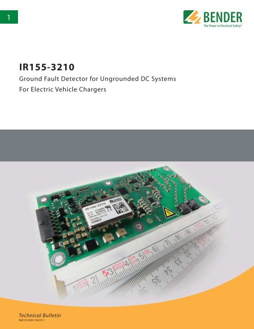
<strong>IR155</strong>-<strong>3210</strong><br />
Ground Fault Detector for Ungrounded DC Systems<br />
For Electric Vehicle Chargers<br />
Preliminary data sheet<br />
Technical Bulletin<br />
NAE1012820 / 04.2011
<strong>IR155</strong>-<strong>3210</strong><br />
Ground fault detector for ungrounded DC systems<br />
For electric vehicle chargers<br />
<strong>IR155</strong>-<strong>3210</strong><br />
Features<br />
• Suitable for 12 V and 24 V systems<br />
• Automatic self-test<br />
• Continuous measurement of insulation<br />
resistance up to 10 MΩ<br />
• Response time < 2 s after power on for<br />
first estimated insulation resistance (SST)<br />
• Response time < 10 s for measured insulation<br />
resistance<br />
• Automatic adaptation to the existing system<br />
leakage capacitance up to 1 μF<br />
• Detection of ground faults and lost<br />
ground connection<br />
• Capability of low voltage detection for<br />
voltages below 500 V, configured at factory<br />
• Automotive rated connector<br />
• Short protected outputs for:<br />
- Fault detection (high side output)<br />
- Measurement value (PWM 5…95%) and<br />
status (f = 10…50 Hz) at high side driver<br />
• Conformal coating (SL1301ECO-FLZ)<br />
• Small footprint and lightweight<br />
• UL2231 recognized<br />
Description<br />
The <strong>IR155</strong>-<strong>3210</strong> is a UL 2231 recognized ground fault detector for ungrounded DC electric<br />
vehicle chargers. The <strong>IR155</strong>-<strong>3210</strong> monitors the system's insulation resistance between<br />
the charger (U n = DC 0…800 V) and ground. The advanced measurement method monitors<br />
both the DC side as well as the AC motor side of the system, even through high system<br />
interference conditions caused by motor control processes. The <strong>IR155</strong>-<strong>3210</strong> has a<br />
very small footprint and is lightweight, and meets the automotive requirements for environmental<br />
conditions.<br />
Alarm messages are output via the integrated and galvanically isolated high-side driver interface.<br />
The interface consists of a status output (OK HS output, gives a go-no go output)<br />
and a measurement output (M HS output, signals the insulation resistance reading). Base<br />
frequency encoded messages allow distinguishing between various alarm messages and<br />
measurement readings.<br />
Function<br />
The <strong>IR155</strong>-<strong>3210</strong> generates a pulsed measuring voltage superimposed on the system via<br />
the terminals L+/L- and E/KE. The currently read insulation resistance value is output as a<br />
PWM signal at the terminal M HS . The connection between the terminals E/KE is continuously<br />
monitored.<br />
Once power is applied, the device performs an initial SST measurement. The device provides<br />
the first estimated insulation resistance reading within a maximum of 2 sec. The<br />
AMP measurement (continuous insulation resistance measurement) begins subsequently.<br />
Faults in the connection wires or functional faults will be automatically recognized and<br />
signaled.<br />
Standards<br />
Corresponding standards and regulations<br />
IEC 61557-1 2007-01<br />
IEC 61557-8 2007-01<br />
ISO 6469-3 2001-11<br />
ISO 23273-3 2006-11<br />
ISO 16750<br />
2006 (E)<br />
IEC 61010-1 2001-02<br />
IEC 60664-1 2007-04<br />
IEC 61326-2-4 2010<br />
e1 acc. 72/245/EWG/EEC<br />
UL 2231-1 2002<br />
UL 2231-2 2002<br />
2
A-ISOMETER® iso-F1<br />
Wiring<br />
HV System DC 0 V…800 V<br />
L-<br />
Connector XLA+<br />
Pin 1+2 L+<br />
Line voltage<br />
2 1 2 1<br />
L+<br />
Connector XLA-<br />
Pin 1+2 L-<br />
Line voltage<br />
Connector XK1A<br />
XLA-<br />
XLA+<br />
XK1A<br />
8 7 6 5 4 3 2 1<br />
Kl.15<br />
E<br />
KE<br />
M HS<br />
NC<br />
NC<br />
OK HS<br />
Kl.31<br />
Kl.31b<br />
Pin 1 KI.31b Ground<br />
Pin 2 KI.15 Supply voltage<br />
Pin 3 KI.31 Ground<br />
Pin 4 KI.31 Ground<br />
Pin 5 M HS Data out, PWM<br />
Pin 6 No connection<br />
Pin 7 No connection<br />
Pin 8 OK HS Status out<br />
Example application<br />
F1<br />
Charger<br />
Supply<br />
coupler<br />
L+<br />
R R F1<br />
F2<br />
L-<br />
Charger IMD<br />
relay<br />
<strong>IR155</strong>-<strong>3210</strong><br />
Charging Circuit<br />
R AE<br />
Charger to vehicle diagnostic (load enable)<br />
Vehicle<br />
coupler<br />
Load enable<br />
relay<br />
R F3<br />
Vehicle Circuit<br />
HV-Battery<br />
Drive enable<br />
relay<br />
IMD<br />
<strong>IR155</strong>-3204<br />
Additional requirements per UL 2231<br />
A product employing a manual test feature shall be marked:<br />
"Test Before Each Use"<br />
The instructions related to perfoming the test and interpreting the<br />
results must be included. These instructions are to state that a device<br />
that produces an unacceptable test result shall not be used.<br />
Example:<br />
During normal operation, the device must respond within 10 seconds<br />
if the insulation resistance of the system falls below the set response<br />
value. A possible test implentation may include switching a<br />
test resistor into the system between the conductors and ground<br />
and a simultaneous measurement of the response time. A device<br />
which takes longer than 10 seconds to respond shall be considered<br />
a failed device and must not be used.<br />
3
Technical data<br />
Supply voltage U S<br />
DC 10…36 V<br />
Nominal supply voltage<br />
DC 12 V / 24 V<br />
Voltage range<br />
10 V…36 V<br />
Max. operational current I S<br />
150<br />
mA<br />
Max. current I k<br />
2 A<br />
6 A / 2 ms Rush-In current<br />
Power dissipation P S<br />
< 2 W<br />
Line L+ / L- Voltage U n<br />
AC 0 V…800 V peak;<br />
0 V…560 V rms (10 Hz…1 kHz)<br />
DC 0 V…800 V<br />
Protective separation (reinforced insulation) between<br />
(L+ / L-) – (Kl.31b, Kl.15, E, KE, M HS , OK HS )<br />
Voltage test<br />
AC 3500 V / 1 min<br />
Under voltage detection<br />
0 V…500 V; Default: 0 V (inactive)<br />
System leakage capacity C e ≤ 1 µF<br />
Measuring voltage U m<br />
+/- 40 V<br />
Measuring current I m at R F = 0 +/- 33 µA<br />
Impedance Z i at 50 Hz<br />
≥ 1.2 MΩ<br />
Internal resistance R i<br />
≥ 1.2 MΩ<br />
Measurement range<br />
0…10 MΩ<br />
Measurement method<br />
<strong>Bender</strong> AMP Technologie<br />
Relative error at SST (≤ 2 s)<br />
Good > 2 * R an ; Bad < 0.5 * R an<br />
Relative error at AMP 0…85 kΩ +/-20 kΩ<br />
100 kΩ…10 MΩ +/-15 %<br />
Relative error Output – M (base frequencies)<br />
+/- 5 % at each frequency<br />
(10 Hz; 20 Hz; 30 Hz; 40 Hz; 50 Hz)<br />
Relative error under voltage detection U n ≥ 100 V +/-10 %;<br />
Response value hysteresis (AMP)<br />
at<br />
U n ≥ 300 V +/-5 %<br />
25 %<br />
Response value R an<br />
100<br />
kΩ…200 kΩ<br />
higher tolerances at R an < 85 kΩ; (Default: 100 kΩ)<br />
Response time t an (OK HS ; SST) t an ≤ 2 s (typ. < 1 s at U n > 100 V)<br />
Response time t an (OK HS ; AMP) t an ≤ 10 s;<br />
d uring self test t an + 10 s<br />
Switch-off time t ab (OK HS ; AMP)<br />
t ab ≤ 26 s<br />
d uring self test t ab + 10 s<br />
Self test time<br />
10 s<br />
( every 5 minutes; has to be added to t an / t ab )<br />
Relative error (SST)<br />
“Good-Value” ≥ 2 * R an<br />
“Bad-Value” ≤ 0.5 * R an<br />
Relative error (AMP) 100 kΩ +/-15%<br />
100 kΩ…1.2 MΩ +/-15% to +/-7%<br />
1.2 MΩ +/-7%<br />
1.2 MΩ…10 MΩ +/-7% to +/-15%<br />
10 MΩ +/-15%<br />
Absolute error (AMP) 0 Ω…85 kΩ +/-20 kΩ<br />
Measurement Output (M)<br />
M HS switches to U S – 2V (<strong>3210</strong>)<br />
(external load to ground necessary) 0 Hz Hi > short to<br />
U b + (Kl.15); Low > IMD off or short to Kl.31<br />
10 Hz Normal Condition<br />
Insulation measuring AMP; starts 10 s after<br />
Power-On; PWM active 5 %…95 %<br />
20 Hz Under voltage condition<br />
Insulation measuring AMP (correct measurement)<br />
starts 10 s after Power-On;<br />
PWM active 5 %…95 %<br />
Under voltage detection 0 V…500 V<br />
(EOL <strong>Bender</strong> configurable).<br />
30 Hz Speed Start<br />
Insulation measuring (only good/bad estimation);<br />
Starts directly after Power-On; response time ≤ 2 s;<br />
PWM 5 %…10 % (good) and 90 %…95 % (bad)<br />
40 Hz IMD Error<br />
IMD error detected; PWM 47.5%…52.5%<br />
50 Hz Ground error<br />
Error on measurement ground line (Kl. 31) detected<br />
PWM 47.5%…52.5%<br />
OK HS Output<br />
OK HS switches to U S – 2V<br />
(external load to ground necessary)<br />
H igh No fault; R F > response value<br />
L ow Insulation resistance ≤ response value<br />
detected; IMD error; ground error,<br />
under voltage detected or IMD off<br />
(ext. pull-down resistor required)<br />
4
Operating principle PWM- driver<br />
• Condition “Normal” and “Under voltage detected” (10Hz; 20Hz)<br />
Duty<br />
cycle 5 % = >50 MΩ (∞)<br />
D uty cycle 50 % = 1200 kΩ<br />
D uty cycle 95 % = 0 kΩ<br />
R F =<br />
90% x 1200 kΩ<br />
dc meas -5%<br />
- 1200 kΩ<br />
dc meas = measured duty cycle (5 %…95 %)<br />
Load current I L<br />
20<br />
mA<br />
Turn-on time to 90 % V OUT Max. 125 µs<br />
Turn-off time to 10 % V OUT Max. 175 µs<br />
Slew rate on 10 to 30 % V OUT Max. 6 V/µs<br />
Slew rate off 70 to 40 % V OUT Max. 8 V/µs<br />
Timing <strong>3210</strong><br />
Operating principle PWM- driver<br />
• Condition “SST” (30Hz)<br />
Operating principle PWM- driver<br />
Duty cycle<br />
5 %…10 % („Good“)<br />
90 % … 95 % („Bad“)<br />
• Condition “Device error” and “Kl.31 fault” (40Hz; 50Hz)<br />
Duty<br />
cycle 47.5% … 52.5 %<br />
Connectors<br />
TYCO-MICRO MATE-N-LOK<br />
1 x 2-1445088-8<br />
(Kl.31b, Kl.15, E, KE, M HS , OK HS )<br />
2 x 2-1445088-2 (L+, L-)<br />
Crimp contacts<br />
TYCO MICRO MATE-N-LOK Gold<br />
14x 1-794606-1<br />
Necessary crimp tongs (TYCO)<br />
91501-1<br />
Operating mode / mounting<br />
Continuous operation / any position<br />
Temperature range<br />
-40 °C…+105 °C<br />
Voltage dropout<br />
≤ 2 ms<br />
Fire protection class acc. UL94<br />
V 0<br />
ESD protection:<br />
Contact discharge – directly to terminals<br />
≤ 10 kV<br />
Contact discharge – indirectly to environment<br />
≤ 25 kV<br />
Air discharge – handling of the PCB<br />
≤ 6 kV<br />
Mounting<br />
Screw mounting: M4 metal screws with locking washers between screw head and PCB.<br />
Torx, T20 with a max. tightening torque of 4 Nm for the screws. Furthermore max. 10 Nm<br />
pressure to the PCB at the mounting points.<br />
Screw and washer kit attached. The max. diameter of the mounting points is 10 mm.<br />
Before mounting the device, ensure sufficient insulation between the device and the vehicle<br />
resp. the mounting points (min. 11.4 mm to other parts). If the IMD is mounted on a metal<br />
or conductive subsurface, this subsurface has to get ground potential (Kl.31; vehicle mass).<br />
Deflection<br />
max. 1 % of the length resp. width of the PCB<br />
Conformal coating<br />
Thick-Film-Laequer<br />
Weight<br />
52 g +/-2 g<br />
5
Ordering Information<br />
<strong>IR155</strong>-<strong>3210</strong> Fixed parameters B 9106 8140<br />
R an = 100 kΩ<br />
Undervoltage: 0 V (inactive)<br />
Measurement output high side<br />
<strong>IR155</strong>-<strong>3210</strong> Parameters customizable at factory B 9106 8140C<br />
R an = 100…200 kΩ (fixed value)<br />
Undervoltage: 0…500 V (fixed value)<br />
Measurement output high side<br />
Dimensions<br />
Dimensions in mm<br />
15<br />
0<br />
5<br />
78.25<br />
135 140<br />
60<br />
55<br />
XLA-<br />
XLA+<br />
XK1A<br />
5<br />
0<br />
The connectors are 1mm longer<br />
than the PCB dimensions<br />
ø 4.2<br />
10mm copper circumferential on the rear<br />
side and 8.4mm on the front side<br />
Document NAE1012820 / 04.2011 / © <strong>Bender</strong> Inc.<br />
North American Headquarters • Coatesville, PA<br />
Toll-Free: 800.356.4266 • Fax: 610.383.7100<br />
Canada • Brampton, ON<br />
Toll-Free: 800-243-2438 • Fax: 905-799-3051<br />
www.bender.org • E-mail: info@bender.org


