

IRDH365 - Bender
IRDH365 - Bender
IRDH365 - Bender

You also want an ePaper? Increase the reach of your titles
YUMPU automatically turns print PDFs into web optimized ePapers that Google loves.
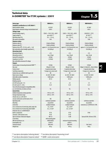
Technical data<br />
A-ISOMETER ® for IT DC systems ≥ 230 V<br />
Chapter 1.5<br />
Device type IRDH265-4.. <strong>IRDH365</strong>-4.. IRDH1065B-4..<br />
Insulation coordination acc. to IEC 60664-1:<br />
Rated insulation voltage AC 630 V AC 630 V AC 500V<br />
Rated impulse withstand voltage/contamination level 6 kV/3 6 kV/3 4 kV/3<br />
Voltage range<br />
Nominal voltage range U n<br />
(3)AC 0 ... 793 V / DC 0... 650 V (3)AC 0 ... 793 V / DC 0... 650 V (3)AC/DC 0 ... 575 V<br />
Supply voltage U S<br />
up to 500 V * 1) up to 500 V * 1) AC 230 V * 1)<br />
Operating range of U S<br />
0.8 ... 1.15 x U S<br />
0.8 ... 1.15 x U S<br />
0.8 ... 1.15 x U S<br />
Max. power consumption 6 VA 6 VA 10 VA<br />
Response values<br />
Response value R an1<br />
10 kΩ to 990 kΩ 10 kΩ to 990 kΩ 10 kΩ to 990 kΩ<br />
Response value R an2<br />
10 kΩ to 990 kΩ 10 kΩ to 990 kΩ 10 kΩ to 990 kΩ<br />
Response time at R F<br />
= 0.5 x R an<br />
and C e<br />
= 1 µF approx. 6 s / see characteristic curve approx. 6 s / see characteristic curve approx. 6 s / see characteristic curve<br />
Max. admissible system leakage capacitance C e<br />
150 (500) µF 150 (500) µF 150 (500) µF<br />
Measuring circuit<br />
Measuring voltage U m<br />
27 V 27 V 27 V<br />
Measuring current I m<br />
max. 230 µA max. 230 µA max. 225 µA<br />
Internal DC resistance R i<br />
120 kΩ 120 kΩ 120 kΩ<br />
Impedance Z i<br />
at 50 Hz >250 kΩ >250 kΩ >250 kΩ<br />
Max. admissible extraneous DC voltage - - -<br />
Outputs<br />
Current output at measuring instrument SKMP * 4) 120 kΩ 120 kΩ 120 kΩ<br />
Max. load 400 µA (12.5 kΩ) 400 µA (12.5 kΩ) 400µA (12.5kΩ)/0/4...20mA (400Ω)<br />
Contact circuit 2 separate alarm relays 2 separate alarm relays 2 separate alarm relays<br />
Switching components 1 change-over contact each 1 change-over contact each 1 change-over contact each<br />
Contact class acc. to DIN IEC 60255 part 0-20 IIB IIB IIB<br />
Rated contact voltage AC 250 V / DC 300 V AC 250 V / DC 300 V AC 250 V / DC 300 V<br />
Admissible number of operations 12000 cycles 12000 cycles 12000 cycles<br />
Making capacity UC 5 A UC 5 A UC 2 A<br />
Breaking capacity<br />
AC 230 V and cos phi = 0.4 2 A 2 A 2 A<br />
DC 220 V and L/R = 0.04 s 0.2 A 0.2 A 0.2 A<br />
Tests of the Electromagnetic Compatibility (EMC)<br />
acc. to EC directives, test data see Annex Yes Yes Yes<br />
General data<br />
Ambient temperature, during operation -10°C to +55°C -10°C to +55°C -10°C to +70°C<br />
Storage temperature range -40°C to +70°C -40°C to +70°C -40°C to +70°C<br />
Climatic class acc. to IEC 60721<br />
(except condensation and formation of ice) 3K5 3K5<br />
Operating mode continuous operation continuous operation continuous operation<br />
Mounting any position any position any position<br />
Connection modular terminals modular terminals connectors acc. to DIN 46 612 / E48<br />
Cross sectional area of connecting cable, single wire 0.2...4 mm 2 0,2...4 mm 2 -<br />
Cross sectional area of connecting cable, flexible 0.2...2.5 mm 2 0,2...2,5 mm 2 -<br />
Protection class acc. to DIN EN 60529<br />
Built-in components IP 30 IP 30 IP 00<br />
Terminals / with terminal covers IP 20 IP 20 -<br />
Type of enclosure /dimension diagram XM 112 X 300 Eurocard 100 x 160 mm (12TE)<br />
Screw fixing with mounting plate - -<br />
DIN rail mounting acc. to DIN EN 50022 enclosure for panel mounting -<br />
Flammability class UL94V-0 UL94V-1 -<br />
Technical manual TGH1249 E TGH1249 E TGH 1264 E<br />
Weight max. 825 g 1075 g 920 g<br />
1.5<br />
* 1) see device description “ordering details“ * 2) see device description “measuring circuit“<br />
* 3) see device description “response values“ * 4) SKMP = scale centre point<br />
Chapter 1.5<br />
Main catalogue part 1 / Insulation monitoring<br />
39
A-ISOMETER ® <strong>IRDH365</strong>-4..<br />
Insulation monitoring devices for IT AC systems with<br />
DC components and IT DC systems<br />
Application in modern power supply systems<br />
• One and three-phase systems with<br />
converter drives<br />
• DC systems with power converters<br />
• Mixed AC/DC supply systems<br />
• UPS systems<br />
• Heaters with phase control<br />
• Systems with switched-mode power<br />
supply<br />
• Systems with very high leakage<br />
capacitances<br />
Product description<br />
The A-ISOMETERS <strong>IRDH365</strong>-4 monitor<br />
today´s power supply systems by microprocessor-controlled<br />
measuring voltage.<br />
These systems frequently contain converters,<br />
power converters, thyristor controls,<br />
and directly connected DC components<br />
and due to interference suppression<br />
arrangements often high system leakage<br />
capacitances to earth exist. The AMP<br />
measuring principle adapts itself<br />
automatically to the respective system<br />
conditions. The voltage range can be<br />
extended with coupling devices. Details<br />
on these devices you will find in chapter<br />
1.9 “Coupling devices“.<br />
Device char acteristics<br />
• Universal for 3/(N)AC systems,<br />
AC/DCsystems up to 793 V and<br />
DC systems up to 650 V.<br />
• The voltage range can be extended<br />
with coupling devices.<br />
• Automatic adaptation to system<br />
leakage capacitances up to 500 µF.<br />
• Safe measuring thanks to the AMP<br />
measuring principle and microcontrollers.<br />
• Two adjustable response values<br />
10 ... 990 kΩ.<br />
• LC display.<br />
• RS485 interface.<br />
• Connection monitoring.<br />
• Automatic self test.<br />
Ordering details<br />
Type Nominal voltage Supply voltage Art. No.<br />
range U n<br />
U S<br />
<strong>IRDH365</strong>-4 AC 0-793/DC 0-650 V AC 230 V B 9106 8006 2)<br />
<strong>IRDH365</strong>-413 AC 0-793/DC 0-650 V AC 90 ... 132 V* B 9106 8011 2)<br />
<strong>IRDH365</strong>-415 AC 0-793/DC 0-650 V AC 400 V B 9106 8012 2)<br />
<strong>IRDH365</strong>-416 AC 0-793/DC 0-650 V AC 500 V B 9106 8025 2)<br />
<strong>IRDH365</strong>-422 AC 0-793/DC 0-650 V DC 19.2 ... 84 V* B 9106 8014 1)<br />
<strong>IRDH365</strong>-423 AC 0-793/DC 0-650 V DC 77 ... 286 V* B 9106 8021 1)<br />
Other supply voltages on request.<br />
* This information represents absolute values for the supply voltage, to which the<br />
working range is not applicable.<br />
1)<br />
only for use in the industrial sector<br />
2)<br />
for use in the household as well as<br />
industrial sector<br />
Measuring principle<br />
<strong>IRDH365</strong>-4 series operates with<br />
the AMP measuring principle.<br />
This ensures safe monitoring of<br />
todays control voltage systems. The Annex<br />
contains a detailed description of the<br />
measuring principle.<br />
Standards<br />
The <strong>IRDH365</strong>-4 series complies with the<br />
standards DIN EN 61557-1<br />
(VDE0413 part1):1998-05, IEC 61557-8,<br />
EN 61557-8 and ASTM F1669M-96.<br />
Details about these standards you will find<br />
in the Annex.<br />
When installing the device, the safety<br />
instructions enclosed with the equipment<br />
must be observed !<br />
Certific ations:<br />
42 Main catalogue part 1 / Insulation monitoring Chapter 1.5
Wiring diagram<br />
1.5<br />
Response time<br />
Accessories<br />
External kΩ measuring instruments<br />
Type<br />
Art. No.<br />
7204-1421 B 986 763<br />
9604-1421 B 986 764<br />
Coupling devices<br />
Type Nominal voltage Art. No.<br />
range U n<br />
AGH150W-4 DC 0 ... 1760 V B 98018006<br />
AGH204S-4 AC 0...1300 /0...1650 V B 914 013<br />
AGH520S AC 0 ... 7200 V B 913 033<br />
Wiring diagrams see chapter 1.9<br />
Chapter 1.5<br />
Main catalogue part 1 / Insulation monitoring<br />
43


