

Over or Under voltage relay SUD472 - Bender
Over or Under voltage relay SUD472 - Bender
Over or Under voltage relay SUD472 - Bender

Create successful ePaper yourself
Turn your PDF publications into a flip-book with our unique Google optimized e-Paper software.
<strong>Over</strong> <strong>or</strong> <strong>Under</strong> <strong>voltage</strong> <strong>relay</strong><br />
<strong>SUD472</strong><br />
Quality System<br />
Certified<br />
ISO 9001<br />
3Ph systems without Neutral<br />
Multiple ranges from 70 VAC to 520 VAC<br />
V<br />
MONITOR<br />
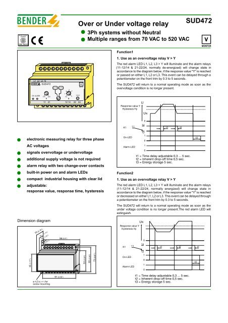
Function1<br />
1. Use as an over<strong>voltage</strong> <strong>relay</strong> V > Y<br />
L1 L2 L3 N<br />
<strong>SUD472</strong><br />
UY<br />
2<br />
3<br />
4<br />
V<br />
MONITOR<br />
The red alarm LED L1, L2, L3 > Y will illuminate and the alarm <strong>relay</strong>s<br />
(11-12/14 & 21-22/24, n<strong>or</strong>mally de-energized) will change state in<br />
acc<strong>or</strong>dance to the diagram below, if the response value "Y" is reached<br />
<strong>or</strong> passed on either L1, L2 <strong>or</strong> L3. This event can be delayed through a<br />
potentiometer on the front trim by 0.3 to 5 seconds.<br />
The <strong>SUD472</strong> will return to a n<strong>or</strong>mal operating mode as soon as the<br />
over<strong>voltage</strong> condition is no longer present.<br />
ON ALARM<br />
270 520<br />
V<br />
11 21<br />
1<br />
TEST<br />
0,3 5<br />
S<br />
12 14 22 24<br />
Response value Y<br />
Hysteresis Hy<br />
U<br />
UN<br />
electronic measuring <strong>relay</strong> f<strong>or</strong> three phase<br />
AC <strong>voltage</strong>s<br />
signals over<strong>voltage</strong> <strong>or</strong> under<strong>voltage</strong><br />
additional supply <strong>voltage</strong> is not required<br />
alarm <strong>relay</strong> with two change-over contacts<br />
built-in power on and alarm LEDs<br />
compact industrial housing with clear lid<br />
adjustable:<br />
response value, response time, hysteresis<br />
K1<br />
On-LED<br />
11<br />
Alarm-LED<br />
14<br />
0<br />
12<br />
1<br />
0<br />
1<br />
0<br />
t1 = Time delay adjustable 0,3 ... 5 sec.<br />
t2 = Inherent drop-off time 0,5 sec.<br />
t3 = Energy st<strong>or</strong>age 5 sec.<br />
Function2<br />
1. Use as an over<strong>voltage</strong> <strong>relay</strong> V > Y<br />
The red alarm LED L1, L2, L3 < Y will illuminate and the alarm <strong>relay</strong>s<br />
(11-12/14 & 21-22/24, n<strong>or</strong>mally energized) will change state in<br />
acc<strong>or</strong>dance to the diagram below, if the response value "Y" is reached<br />
<strong>or</strong> decreased on either L1, L2 <strong>or</strong> L3. This event can be delayed through<br />
a potentiometer on the front trim by 0.3 to 5 seconds.<br />
The <strong>SUD472</strong> will return to a n<strong>or</strong>mal operating mode as soon as the<br />
under <strong>voltage</strong> condition is no longer present.The red alarm LED will<br />
extinguish.<br />
t1<br />
t2<br />
t3<br />
Dimension diagram<br />
70 (2.76")<br />
44 (1.73")<br />
31 (1.22")<br />
5 (0.2")<br />
99 (3.9")<br />
Response value Y<br />
Hysteresis Hy<br />
UN<br />
0<br />
14<br />
K1 11<br />
t1 t2 t1<br />
45 (1.77")<br />
53 (2.09")<br />
65 (2.56")<br />
73 (2.87")<br />
On-LED<br />
Alarm-LED<br />
12<br />
1<br />
0<br />
1<br />
0<br />
t3<br />
ø 4,3 (0.17") f<strong>or</strong><br />
screw mounting<br />
91 (3.58")<br />
t1 = Time delay adjustable 0,3 ... 5 sec.<br />
t2 = Inherent drop-off time 0,5 sec.<br />
t3 = Energy st<strong>or</strong>age 5 sec.
Technical data SUA472<br />
Monit<strong>or</strong>ed System<br />
Nominal system <strong>voltage</strong> UN<br />
3Ph AC 110, 230 <strong>or</strong> 400V<br />
Power consumption max.<br />
< 3 VA<br />
Response values<br />
0.7 ... 1.3Un<br />
Influence of ambient temperature < 0.05 % / °C<br />
Switching hysteresis 3 ... 4 %<br />
Delay on response, (adjustable)<br />
0.3 ...5 sec.<br />
Operating mode (f<strong>or</strong> under <strong>voltage</strong> operation) N/Open operation<br />
Operating mode (f<strong>or</strong> over<strong>voltage</strong> operation) N/Closed operation<br />
Contact circuit<br />
Alarm <strong>relay</strong>s<br />
SPDT dry contacts<br />
Contact class acc. to DIN IEC 60255 Teil 0-20<br />
IIB<br />
Rated contact <strong>voltage</strong><br />
AC 250 V/DC 300 V<br />
Admissible number of operations<br />
12000 cycles<br />
Making capacity<br />
UC 5 A<br />
Breaking capacity<br />
at AC 230 V and cos phi = 0.4<br />
AC 2 A<br />
at DC 220 V and L/R = 0.04 s<br />
DC 0.2 A<br />
Type tests<br />
Test of the Electromagnetic Compatibility (EMC)<br />
Interferences acc. prEN 50082-2<br />
(only f<strong>or</strong> industrial use)<br />
Mechanical tests<br />
Shock resistance acc. to IEC 6068-2-27<br />
15g / 11 ms<br />
Bumping acc. to IEC 6068-2-29<br />
40g / 6 ms<br />
Vibration strength acc. to IEC 6068-2-6 10...150 Hz / 0.15 mm - 2g<br />
Environmental conditions<br />
Ambient temperature, during operation<br />
-5°C...+50°C<br />
St<strong>or</strong>age temperature range<br />
-25°C...+60°<br />
Climatic class acc. to IEC 721 3K5, except condensation and<br />
f<strong>or</strong>mation of ice<br />
General data<br />
Operation class continuous operation<br />
Mounting<br />
any position<br />
Type of connection Terminal block<br />
Wire cross section<br />
single wire AWG 2 x 1 ... 1.5 mm 2<br />
fine braid AWG 16 2 x 0.75 ... 1.5 mm 2<br />
Rapid mounting<br />
DIN Rail <strong>or</strong> screw mounting<br />
Protection class acc. to EN 60529<br />
Internal components IP 50<br />
Terminals/with terminal covers IP 20<br />
Type of casing<br />
X470<br />
Flammability class<br />
UL94V-0<br />
Weight<br />
approx. 210 g<br />
Wiring diagram<br />
7<br />
L1<br />
1 2<br />
L2<br />
L3<br />
UY<br />
Y<br />
t<br />
ON ALARM TEST<br />
270 520<br />
0,3 5<br />
V ALARM s<br />
11 21<br />
12 14 22 24<br />
11<br />
4 5 6<br />
21<br />
12 14 22 24<br />
Legend to the wiring diagram<br />
3<br />
L1<br />
L2<br />
L3<br />
1 On LED<br />
2 Alarm LED<br />
3 Test Push button<br />
4 Dial f<strong>or</strong> adjustable response value<br />
5 Select<strong>or</strong> dial f<strong>or</strong> over <strong>or</strong> under<strong>voltage</strong> mode<br />
6 Dial f<strong>or</strong> adjustable time delay<br />
7 Alarm <strong>relay</strong> contacts SPDT<br />
Type UN Response Hz Time Art#<br />
settings<br />
delay<br />
<strong>SUD472</strong> 3AC110V AC 70-140 50-60Hz 0.3-5 B933219<br />
<strong>SUD472</strong> 3AC230V AC 150-300 50-60Hz 0.3-5 B933170<br />
<strong>SUD472</strong> 3AC400V AC 270-520 50-60Hz 0.3-5 B933702<br />
UN<br />
Nominal <strong>voltage</strong> of the monit<strong>or</strong>ed system<br />
BENDER Industrial Products<br />
700 Fox Chase, Coatesville PA 19320<br />
Tel. (800) 356-4266 - Fax. (610) 383-7100<br />
www.bender<strong>relay</strong>.com


