

View PDF - Bender
View PDF - Bender
View PDF - Bender

Create successful ePaper yourself
Turn your PDF publications into a flip-book with our unique Google optimized e-Paper software.
3<br />
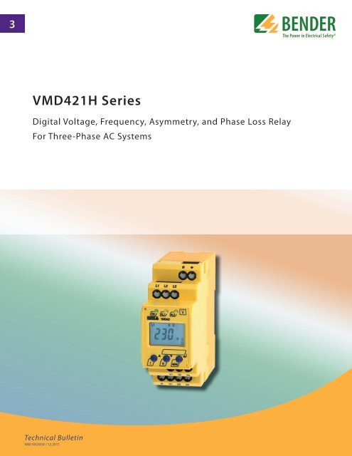
VMD421H Series<br />
Digital Voltage, Frequency, Asymmetry, and Phase Loss Relay<br />
For Three-Phase AC Systems<br />
Technical Bulletin<br />
NAE1032050 / 12.2011
VMD421H<br />
Multi-functional voltage relay for frequency, overvoltage, undervoltage,<br />
phase sequence, phase loss, and asymmetry monitoring<br />
for three-phase AC systems<br />
VMD420<br />
Features<br />
• Undervoltage, overvoltage and frequency<br />
monitoring in three-phase AC systems<br />
0…500 V<br />
• Asymmetry, phase sequence, and phase<br />
loss monitoring<br />
• Powered by monitored system<br />
• Various alarms may be individually<br />
enabled/disabled and assigned to separate<br />
output contacts<br />
• Start-up delay, response delay, delay on<br />
release<br />
• Adjustable switching hysteresis<br />
• RMS measurement (AC)<br />
• Digital LCD display with real-time readings<br />
and onboard menu<br />
• Automatic preset function available<br />
when first connecting device<br />
• LEDs: Power On, Alarm 1, Alarm 2<br />
• Memory stores last alarm value<br />
• Non-volatile memory for settings<br />
• Continuous self monitoring<br />
• Internal test/reset button<br />
• Two separate SPDT alarm relays (gold-plated<br />
relay contacts)<br />
• Normally energized or normally de-energized<br />
operation<br />
• Latching or non-latching operation<br />
• Password protection for device setting<br />
• Sealable transparent cover<br />
• Two-module enclosure (36 mm)<br />
• RoHS compliant<br />
Description<br />
The VMD421H series monitors overfrequency, underfrequency, overvoltage, and undervoltage<br />
in three-phase AC systems. Asymmetry, phase sequence, and phase loss may also<br />
be monitored. Voltages are measured as RMS values. Each alarm may be individually activated<br />
or deactivated based on the system requirements. Three separate time delays (startup<br />
delay, alarm response delay, and delay on release) allow the VMD420 to be tailored<br />
to specific applications. Two SPDT alarm contacts may be separately assigned individual<br />
alarms.<br />
The digital LCD display shows the currently read value in real-time. When an alarm is activated,<br />
the value is stored in the device's history. The VMD421H is powered by the monitored<br />
system. Consult the VMD420 for a version powered by an external supply voltage.<br />
Typical applications<br />
• General purpose three-phase AC monitoring of voltage-sensitive machines and electrical<br />
installations<br />
• Monitoring of standby and emergency supply systems<br />
• Supply voltage monitoring of portable loads<br />
• Phase protection of three-phase motors<br />
• Asymmetrical load protection<br />
Function<br />
Once the supply voltage is applied, the startup delay "t" is activated. Measured voltage<br />
and frequency values that may cause an alarm will not activate until after the startup delay<br />
is complete.<br />
Each type of alarm may be assigned an individual value. Two separate alarm states ("R1"<br />
and "R2") may then be assigned any combination of these alarms to trip their respective<br />
contacts. When any alarm has been activated, the respone delay “t on1/2” will activate.<br />
Once the response delay has elapsed, if the alarm is still active, the appropriate contact<br />
will trip and the alarm LEDs light. Once the alarm has cleared, the delay on release “t off”<br />
begins. Once this delay has elapsed and the alarm is still cleared, the appropriate contact<br />
will switch back.<br />
If the device is set to operate in latching mode ("fault memory"), the device must be manually<br />
reset if it goes into alarm. If it is set to non-latching mode, the alarm will automatically<br />
clear itself. Regardless of this setting, the last alarm value will be stored in the<br />
device's onboard history. Device settings are stored in non-volatile memory and will remain<br />
set even with a loss of supply voltage.<br />
Preset function<br />
After connecting the device for the first time, this optional feature will determine the nominal<br />
system voltage and response values for overvoltage, undervoltage, overfrequency,<br />
and underfrequency will be automatically set. These settings may be changed once the<br />
preset is run. The preset function may be re-run at a later time via the device's onboard<br />
menu.<br />
Approvals
Front display<br />
Wiring<br />
1<br />
2 3<br />
1<br />
4<br />
4<br />
5<br />
6 7<br />
1 - Power On LED “ON” (green); lights when supply voltage is applied<br />
and flashes in the event of system fault alarm.<br />
2 - Alarm LED “AL1” (yellow), lights when the overvoltage, frequency,<br />
asymmetry, or phase loss alarm is active, and flashes<br />
in the event of a system fault alarm.<br />
3 - Alarm LED “AL2” (yellow), lights when the undervoltage, frequency,<br />
asymmetry, or phase loss alarm is active, and flashes<br />
in the event of a system fault alarm.<br />
4 - Multi-functional LCD display<br />
5 - Test button “T”: UP key: Change displayed value, move downwards<br />
in the menu or change parameters.<br />
Holding for > 1.5 s initiates a self-test.<br />
6 - Reset “R” button: DOWN key: Change displayed value, move<br />
downwards in the menu or change parameters.<br />
Holding for > 1.5s resets the device.<br />
7 - MENU key: Enter key: Confirms / changes parameters.<br />
When on the main screen, holding for > 1.5 s en<br />
ters the main menu.<br />
When in the menu, holding for > 1.5 s cancels<br />
an action or moves back a step in the<br />
menu structure.<br />
2<br />
3<br />
1 - Connection to the system/load being monitored<br />
2 - Alarm relay K1: Configurable for all available alarms<br />
3 - Alarm relay K2: Configurable for all available alarms<br />
4 - 5 A fuses required for short circuit protection<br />
Ordering information<br />
Type Supply voltage U S Nominal system voltage U n* Display range Response value Art. No.<br />
VMD421H-D-3 -- 3(N)AC 15…460 Hz / 70…500 V AC 70…500 V AC 70…500 V B 9301 0007<br />
* absolute values<br />
Accessories<br />
Type<br />
Art No.<br />
Mounting clip for screw fixing (1 piece per device) B 9806 0008
Sample timing diagram: Voltage monitoring<br />
Dimensions<br />
Dimensions in inches<br />
Open the front plate cover in direction of<br />
arrow.<br />
4.3”<br />
3.3”<br />
2.6”<br />
1.4”<br />
0.08”<br />
1.8”<br />
2.7”<br />
3.5”<br />
0.08”<br />
Screw fixing<br />
Note: Additional clip required for screw<br />
mounting (see ordering information).<br />
t - Start-up delay t an - Response time toff - Delay on release<br />
Sample timing diagram: Phase loss, phase sequence, asymmetry<br />
3.94”<br />
4.57”<br />
t - Start-up delay t an - Response time t off - Delay on release
Technical data: VMD421H<br />
Insulation coordination acc. to IEC 60664-1 / IEC 60664-3<br />
Rated insulation voltage<br />
400 V<br />
Rated impulse voltage/pollution degree<br />
4 kV / III<br />
Protective separation (reinforced insulation) between<br />
(N, L1, L2, L3) - (11, 12, 14) - (21, 22, 24)<br />
Voltage test acc. to IEC 61010-1:<br />
(N, L1, L2, L3) - (11, 12, 14)<br />
3.32 kV<br />
(N, L1, L2, L3) - (21, 22, 24)<br />
2.21 kV<br />
Supply voltage<br />
Supply voltage U S<br />
Power consumption<br />
Measuring circuit<br />
Measuring range (r.m.s. value) (L-N)<br />
Measuring range (r.m.s. value) (L-L)<br />
Rated frequency f n<br />
Frequency display range<br />
none (internally supplied by Un)<br />
≤ 5 VA<br />
AC 0…288 V<br />
AC 0…500 V<br />
15…460 Hz<br />
10…500 Hz<br />
Response values<br />
Type of distribution system<br />
3(N) AC / 3 AC (3 AC)*<br />
Undervoltage < U (Alarm 2) (measuring method: 3Ph / 3n ) AC 70…500 V / 70…288 V<br />
Overvoltage > U (Alarm 1) (measuring method: 3Ph / 3n ) AC 70…500 V / 70…288 V<br />
Resolution of setting U<br />
1 V<br />
Preset function for 3 AC measurement:<br />
Undervoltage< U (0.85 U n)* for U n = 400 V/ 208 V<br />
340 V / 177 V<br />
Overvoltage > U (1.1 U n)* for U n = 400 V/ 208 V<br />
440 V / 229 V<br />
Preset function for 3(N)AC measurement:<br />
Undervoltage < U (0.85 U n)* for U n = 230 V / 120 V<br />
196 V / 102 V<br />
Overvoltage > U (1.1 U n)* for U n = 230 V / 120 V<br />
253 V / 132 V<br />
Asymmetry 5…30 % (30 %)*<br />
Phase failure<br />
by setting of the asymmetry<br />
Phase sequence<br />
clockwise/ anticlockwise rotation (off)*<br />
Relative percentage error, voltage at 50 Hz / 60 Hz<br />
±1.5 %, ±2 digits<br />
Relative percentage error in the voltage range 15…460 Hz<br />
±3 %, ±2 digits<br />
Hysteresis U 1…40 % (5 %)*<br />
Underfrequency < Hz<br />
10…500 Hz<br />
Overfrequency > Hz<br />
10…500 Hz<br />
Resolution of setting f 10.0…99.9 Hz<br />
0.1 Hz<br />
Resolution of setting f 100…500 Hz<br />
1 Hz<br />
Preset function:<br />
Underfrequency for f n = 16.7 Hz / 50 Hz / 60 Hz / 400 Hz 16.2 Hz / 49.5 Hz / 59.5 Hz / 399 Hz<br />
Overfrequency for f n = 16.7 Hz / 50 Hz / 60 Hz / 400 Hz 17.2 Hz / 50.5 Hz / 60.5 Hz / 401 Hz<br />
Hysteresis frequency Hys Hz<br />
0.2…2 Hz (0.2 Hz)*<br />
Relative percentage error in the frequency range 15…460 Hz ±0.2 %, ±1 digits<br />
Specified time<br />
Start-up delay t<br />
0…99 s (0 s)*<br />
Response delay t on1/2<br />
0…99 s (0 s)*<br />
Delay on release t off<br />
0…99 s (0.5 s)*<br />
Operating time voltage t ae<br />
140 ms<br />
Operating time frequency t ae<br />
335 ms<br />
Response time t antan = tae + ton1/2<br />
Discharging time energy backup on power failure<br />
2.5 s<br />
Charging time energy storage<br />
60 s<br />
Recovery time t b<br />
≤ 300 ms<br />
Displays, memory<br />
Display<br />
LC display, multi-functional, not illuminated<br />
Display range measured value <br />
AC/DC 0…500 V<br />
Operating error, voltage at 50 Hz / 60 Hz<br />
±1.5 %, ±2 digits<br />
Relative percentage error in the voltage range 15…460 Hz<br />
±3 %, ±2 digits<br />
Relative percentage error in the frequency range 15…460 Hz ±0.2 %, ±1 digits<br />
History memory (HiS) for the first alarm value data record measured values<br />
Password<br />
off / 0…999 (off)*<br />
Fault memory (M) alarm relay<br />
on / off / con (on)*<br />
Switching elements<br />
Number of changeover contacts 2 x 1 (K1, K2)<br />
Operating principle<br />
normally energized or normally deenergized operation<br />
K2: Err, < U, > U, Asy, < Hz, > Hz, PHS (undervoltage < U, asymmetry Asy, N/E operation n.c.)*<br />
K1: Err, < U, > U, Asy, < Hz, > Hz, PHS (overvoltage >U, asymmetry Asy, N/D operation n.o.)*<br />
Electrical service life under rated operating conditions, number of cycles 10 000<br />
Fault memory<br />
on / off (on)*<br />
Contact data acc. to IEC 60947-5-1:<br />
Utilization category AC 13 AC 14 DC-12 DC-12 DC-12<br />
Rated operational voltage 230 V 230 V 24 V 110 V 220 V<br />
Rated operational current 5 A 3 A 1 A 0.2 A 0.1 A<br />
Minimum contact load<br />
1 mA at AC / DC 10 V<br />
Environment / EMC<br />
EMC IEC 61326-1<br />
Operating temperature -13 ºF…+131 ºF (-25 ºC…+55 ºC)<br />
Classification of climatic conditions acc. to IEC 60721:<br />
Stationary use (IEC 60721-3-3)<br />
3K5 (except condensation and formation of ice)<br />
Transport (IEC 60721-3-2)<br />
2K3 (except condensation and formation of ice)<br />
Storage (IEC 60721-3-1)<br />
1K4 (except condensation and formation of ice)<br />
Classification of mechanical conditions acc. to IEC 60721:<br />
Stationary use (IEC 60721-3-3)<br />
3M4<br />
Transport (IEC 60721-3-2)<br />
2M2<br />
Storage (IEC 60721-3-1)<br />
1M3<br />
Connection<br />
Connection push-wire terminals<br />
Connection properties:<br />
rigid 0.2…2.5 mm² ( AWG 24…14)<br />
Flexible without ferrules 0.2…2.5 mm² ( AWG 24…14)<br />
Flexible with ferrules 0.2…1.5 mm² ( AWG 24…16)<br />
Stripping length 10 mm<br />
Opening force 50 N<br />
Test opening, diameter 2.1 mm<br />
Other<br />
Operating mode<br />
continuous operation<br />
Mounting position<br />
vertically, see dimension diagram<br />
Degree of protection, internal components (IEC 60529)<br />
IP30<br />
Degree of protection, terminals (IEC 60529)<br />
IP20<br />
Enclosure material<br />
polycarbonate<br />
Flammability class UL94 V-0<br />
DIN rail mounting acc. to IEC 60715<br />
Screw fixing<br />
2 x M4 with mounting clip<br />
Product standard IEC 61010-1 and according to IEC 60255-6<br />
Operating manual<br />
TGH1405<br />
Weight<br />
≤ 240 g<br />
( )* = factory setting
North American Headquarters • Coatesville, PA<br />
Toll-Free: 800.356.4266 • Fax: 610.383.7100<br />
T M<br />
Canada • Brampton, ON<br />
Toll-Free: 800-243-2438 • Fax: 905-799-3051<br />
Document NAE1032050 / 12.2011 / © <strong>Bender</strong> Inc.<br />
www.bender.org • E-mail: info@bender.org


