

2 Dual Isolated Power Panels - Bender
2 Dual Isolated Power Panels - Bender
2 Dual Isolated Power Panels - Bender

Create successful ePaper yourself
Turn your PDF publications into a flip-book with our unique Google optimized e-Paper software.
2<br />
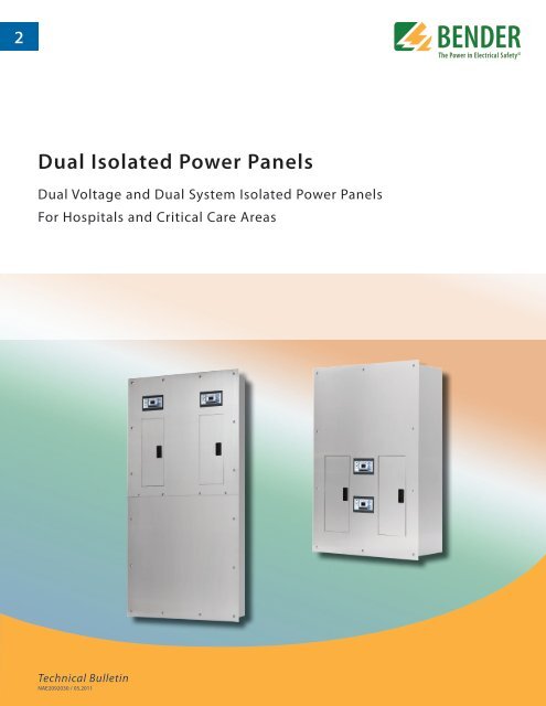
<strong>Dual</strong> <strong>Isolated</strong> <strong>Power</strong> <strong>Panels</strong><br />
<strong>Dual</strong> Voltage and <strong>Dual</strong> System <strong>Isolated</strong> <strong>Power</strong> <strong>Panels</strong><br />
For Hospitals and Critical Care Areas<br />
Technical Bulletin<br />
NAE2092030 / 05.2011
BENDER Inc. • 700 Fox Chase, Coatesville PA 19320 • Ph: 800-356-4266 / 610-383-9200 • Fax: 610-383-7100<br />
<strong>Dual</strong> <strong>Isolated</strong> <strong>Power</strong> <strong>Panels</strong><br />
<strong>Dual</strong> Voltage and <strong>Dual</strong> System <strong>Isolated</strong> <strong>Power</strong> <strong>Panels</strong><br />
for hospitals and other critical care areas<br />
Introduction<br />
BENDER <strong>Isolated</strong> <strong>Power</strong> <strong>Panels</strong> are designed to provide isolated power to electrical power<br />
systems in operating rooms and other critical areas. Designed in strict compliance with UL<br />
1047, UL 1022, and UL 50, BENDER isolated power panels offer the most up-to-date technology<br />
for all isolated power distribution requirements.<br />
<strong>Dual</strong> Voltage <strong>Isolated</strong> <strong>Power</strong> Panel<br />
Features<br />
• <strong>Power</strong> Distribution: Loadcenters available<br />
for either plug-in or bolt-on circuit<br />
breakers<br />
• Mounting: Available for flush- or surfacemounted<br />
applications<br />
• Advanced technology: The LIM2010 line<br />
isolation monitor features self-testing,<br />
self-calibration, and a wide variety of<br />
alarms including voltage, overload, and<br />
overtemperature monitoring<br />
• Standards: Listed to UL 1047, the standard<br />
for isolated power system equipment<br />
• Warranty: Industry-first 5 year warranty<br />
Standard Features: <strong>Dual</strong> Voltage Panel<br />
<strong>Dual</strong> voltage isolated power panels provide two separate voltage outputs using a single<br />
isolation transformer. A standard dual voltage panel consists of the following:<br />
• One (1) single-phase isolation transformer with dual secondary outputs (120 V side and<br />
208 V or 240 V side)<br />
• Two (2) BENDER LIM2010 Line Isolation Monitors (LIM)<br />
• Two (2) Reference ground buses<br />
• One (1) Primary circuit breaker<br />
• One (1) Secondary main circuit breaker for 120 V side<br />
• Eight (8) branch circuit breakers for 120 V side, field-convertable up to 16<br />
• One (1) Secondary main circuit breaker for 208 V or 240 V side<br />
• Provision for two (2) 2-pole branch circuit breakers for 208 V or 240 V side<br />
Standard Features: <strong>Dual</strong> System Panel<br />
<strong>Dual</strong> system panels provide two separate voltage outputs from two isolation transformers.<br />
This system is equivalent to two independent standard isolated power panels in one enclosure.<br />
A standard dual system panel consists of the following:<br />
• Two (2) single-phase isolation transformers<br />
• Two (2) BENDER LIM2010 Line Isolation Monitor (LIM)<br />
• Two (2) Reference ground buses<br />
• Two (2) Primary circuit breakers<br />
• Branch circuit breakers (Qty. 8 standard, field-convertable up to 16 per system)<br />
Backbox<br />
All backboxes are fabricated from a minimum of 14GA galvanized steel. Surface mounted<br />
enclosures are finished with a coat of hospital ivory baked enamel.<br />
Front Trim<br />
Manufactured from a minimum of 14GA type 304 stainless steel with a #4 brushed finish,<br />
the front trim contains two doors with hidden hinges and a flush mounted key lock covering<br />
the loadcenter(s). The front trim for flush-mounted units extends 1" on all sides of the<br />
backbox. For surface-mounted panelboards, the front trim has the same dimensions as the<br />
enclosure.<br />
Line Isolation Monitor<br />
The BENDER LIM2010 series Line Isolation Monitor provides both digital and analog displays.<br />
The LIM is available with readouts and response values of 2 mA or 5 mA. The<br />
LIM2010 utilizes a unique measuring principle and is capable of detecting all combinations<br />
of capacitive and resistive faults, including balanced, unbalanced, and hybrid faults. The<br />
LIM contributes less than 35 μA to the Total Hazard Current (THC).<br />
Loadcenter<br />
The loadcenter is an integral part of the isolated power panel. Included is a primary circuit<br />
breaker which provides protection for the isolation transformer. All isolated power panels<br />
may accommodate either plug-in (snap-in) or bolt-on branch circuit breakers.<br />
2
BENDER<br />
BENDER<br />
S AFE<br />
TEST<br />
S AFE<br />
TEST<br />
TOTAL<br />
HAZARD<br />
CURRENT<br />
TRANSF ORMER<br />
LO AD<br />
TOTAL<br />
HAZARD<br />
CURRENT<br />
TRANSF ORMER<br />
LO AD<br />
%<br />
%<br />
mA<br />
mA<br />
m A<br />
mA<br />
>80%<br />
mA<br />
m A<br />
>80%<br />
H AZA RD<br />
MUTE<br />
LIM2000plus<br />
H AZA RD<br />
MUTE<br />
LIM2000plus<br />
Sample Outline: <strong>Dual</strong> Voltage <strong>Isolated</strong> <strong>Power</strong> Panel<br />
w<br />
d"<br />
1.000"<br />
PLAN<br />
W<br />
A<br />
1.000"<br />
15<br />
16<br />
11<br />
12 12<br />
H<br />
9<br />
17<br />
13<br />
10<br />
8<br />
18 17 FRONT 18 16<br />
9<br />
5<br />
6<br />
7<br />
13<br />
8<br />
A 1<br />
10<br />
d<br />
VIEW A - A<br />
2<br />
h<br />
3<br />
19<br />
4<br />
14<br />
1 - Stainless steel front trim<br />
2 - Backbox, galvanized steel<br />
3 - Backplate, galvanized steel<br />
4 - Backplate mounting bracket<br />
5 - Transformer shelf<br />
6 - Transformer shelf mounting bracket<br />
7 - Circuit breaker deadfront<br />
8 - Stainless steel door with lock<br />
9 - LIM fuses (optional)<br />
10 - LIM circuit breaker, 2P (optional)<br />
11 - Main, primary circuit breaker, 2P<br />
12 - Main, secondary circuit breaker, 2P<br />
13 - Branch circuit breakers, 2P<br />
14 - Loadcenter<br />
15 - Isolation transformer, dual secondary,<br />
single-phase<br />
16 - Line isolation monitor (LIM), single-phase<br />
17 - LIM connector plate<br />
18 - Ground bus<br />
19 - Distribution blocks<br />
Sample Wiring Diagram: <strong>Dual</strong> Voltage <strong>Isolated</strong> <strong>Power</strong> Panel<br />
120 V Side 208 or 240 V Side<br />
3
Ordering Information: <strong>Dual</strong> Voltage <strong>Isolated</strong> <strong>Power</strong> Panel<br />
BENDER dual voltage panels are comprised of four assembly types: the transformer, backbox, front trim, and interior.<br />
STEP 1: Interior - <strong>Dual</strong> Voltage Panel<br />
I D<br />
- 2 5 B B<br />
1 0<br />
S P<br />
- A 3 2<br />
1<br />
2 3<br />
4<br />
5<br />
6<br />
7<br />
1 - KVA rating of transformer<br />
25: 25 kVA<br />
2 - Primary voltage of transformer<br />
B: 208 V E: 480 V<br />
C: 240 V H: 220 V<br />
D: 277 V J: 380 V<br />
3 - Secondary voltage of transformer<br />
B: 208 V C: 240 V<br />
4 - KVA rating of 120 V secondary<br />
10: 10 kVA<br />
5 - Loadcenter/Panelboard Manufacturer<br />
SP: Square D, Plug-On (Snap-In)<br />
SB: Square D, Bolt-On<br />
CP: Cutler-Hammer, Plug-On (Snap-In)<br />
CB: Cutler-Hammer, Bolt-On<br />
GP: General Electric, Plug-On (Snap-In)<br />
6 - Branch circuit breaker(s) rating, 208 or 240 V side<br />
A2: 20 A A5: 50 A<br />
A3: 30 A A6: 60 A<br />
7 - Qty. of branch circuit breakers, 208 or 240 V side<br />
1: One 2: Two<br />
STEP 2: Transformer<br />
X M<br />
STEP 3: Backbox<br />
2 5 B B 1 0<br />
1<br />
2 3 4<br />
1 - KVA rating of transformer<br />
25: 25 kVA<br />
2 - Primary voltage of transformer<br />
B: 208 V E: 480 V<br />
C: 240 V H: 220 V<br />
D: 277 V J: 380 V<br />
3 - Secondary voltage of transformer<br />
B: 208 V C: 240 V<br />
4 - KVA of 120 V secondary<br />
10: 10 kVA<br />
STEP 4: Front Trim<br />
B 5 1 3 4 1 4<br />
T 5 3 3 6<br />
1 2<br />
3<br />
4<br />
1 2<br />
4<br />
1 - Height of backbox<br />
51: 51"<br />
2 - Width of backbox<br />
34: 34"<br />
3 - Depth of backbox<br />
14: 14"<br />
4 - Type of mounting<br />
S: Surface<br />
If flush mounted, leave this item blank.<br />
1 - Height of front trim<br />
53: 53", Flush Mount<br />
51: 51", Surface Mount<br />
2 - Width of front trim<br />
36: 36", Flush Mount<br />
34: 34", Surface Mount
BEND ER<br />
SAFE<br />
TEST<br />
TOTA L<br />
H AZ ARD<br />
C UR RE NT<br />
TRA NS FORMER<br />
LOAD<br />
mA<br />
mA<br />
mA<br />
MUTE<br />
LIM2000plus<br />
BEN DER<br />
SAFE<br />
TEST<br />
T OT AL<br />
HA ZAR D<br />
C U RR EN T<br />
m A<br />
mA<br />
mA<br />
TR AN SFOR ME R<br />
LOA D % >80%<br />
HAZARD<br />
M UTE<br />
LIM2000plus<br />
Sample Outline: <strong>Dual</strong> System <strong>Isolated</strong> <strong>Power</strong> Panel<br />
w<br />
1 - Stainless steel front trim, two (2) sections<br />
2 - Backbox, galvanized steel<br />
d<br />
1.000"<br />
3 - Backplate, galvanized steel<br />
PLAN<br />
W<br />
A<br />
d<br />
4 - Backplate mounting bracket<br />
5 - Heat shield, vertical<br />
1.000"<br />
6 - Heat shield, horizontal<br />
15<br />
16<br />
% >8 0% HAZARD<br />
15<br />
16<br />
7 - Circuit breaker deadfront<br />
8 - Stainless steel door with lock<br />
11<br />
9<br />
12<br />
11<br />
H1<br />
9<br />
12<br />
3<br />
4<br />
9 - LIM fuses (optional)<br />
10 - LIM circuit breaker, 2P (optional)<br />
11 - Main circuit breaker, 2P<br />
8<br />
7<br />
13<br />
12 - Branch circuit breakers, 2P<br />
10<br />
17<br />
H<br />
8<br />
10<br />
17<br />
h<br />
13 - Loadcenter<br />
14 - Isolation transformer, single-phase<br />
6<br />
15 - Line isolation monitor (LIM), single-phase<br />
16 - LIM connector plate<br />
5<br />
5<br />
17 - Ground bus<br />
H2<br />
14<br />
14<br />
1<br />
2<br />
FRONT<br />
A<br />
VIEW A - A<br />
Sample Wiring Diagram: <strong>Dual</strong> System <strong>Isolated</strong> <strong>Power</strong> Panel<br />
System 1 System 2<br />
5
Ordering Information<br />
BENDER dual system panels are comprised of four assembly types: the transformers, backbox, front trim, and interior.<br />
STEP 1: Interior - <strong>Dual</strong> System Panel<br />
I X<br />
- 1 0 B A<br />
- 1 0 B A -<br />
S P<br />
1<br />
2 3<br />
4<br />
5 6<br />
7<br />
System 1<br />
1 - System 1 - Total kVA<br />
03: 3 kVA 07: 7.5 kVA<br />
05: 5 kVA 10: 10 kVA<br />
2 - System 1 - Primary voltage<br />
A: 120 V G: 110 V<br />
B: 208 V H: 220 V<br />
C: 240 V I: 230 V<br />
D: 277 V J: 380 V<br />
E: 480 V<br />
3 - System 1 - Secondary voltage<br />
A: 120 V G: 110 V<br />
B: 208 V H: 220 V<br />
C: 240 V I: 230 V<br />
System 2<br />
4 - System 2 - Total kVA<br />
03: 3 kVA 07: 7.5 kVA<br />
05: 5 kVA 10: 10 kVA<br />
5 - System 2 - Primary voltage<br />
A: 120 V G: 110 V<br />
B: 208 V H: 220 V<br />
C: 240 V I: 230 V<br />
D: 277 V J: 380 V<br />
E: 480 V<br />
6 - System 2 - Secondary voltage<br />
A: 120 V G: 110 V<br />
B: 208 V H: 220 V<br />
C: 240 V I: 230 V<br />
Both Systems<br />
7 - Loadcenter/Panelboard Manufacturer<br />
SP: Square D, Plug-On (Snap-In)<br />
SB: Square D, Bolt-On<br />
CP: Cutler-Hammer, Plug-On (Snap-In)<br />
CB: Cutler-Hammer, Bolt-On<br />
GP: General Electric, Plug-On (Snap-In)<br />
STEP 2: Transformer* (Two Required)<br />
X M<br />
1 0 B A<br />
1<br />
2 3<br />
Note*: This step must be completed<br />
twice. Two transformers are required<br />
for a complete dual system isolated power<br />
panel.<br />
1 - Total kVA of transformer<br />
03: 3 kVA 07: 7.5 kVA<br />
05: 5 kVA 10: 10 kVA<br />
2 - Primary voltage of transformer<br />
A: 120 V G: 110 V<br />
B: 208 V H: 220 V<br />
C: 240 V I: 230 V<br />
D: 277 V J: 380 V<br />
E: 480 V<br />
3 - Secondary voltage of transformer<br />
A: 120 V G: 110 V<br />
B: 208 V H: 220 V<br />
C: 240 V I: 230 V<br />
6
STEP 3: Backbox<br />
STEP 4: Front Trim<br />
B 7 1 3 4 0 8<br />
T 7 3 3 6<br />
1 2<br />
3<br />
4<br />
1 2<br />
1 - Height of backbox<br />
71: 71"<br />
2 - Width of backbox<br />
34: 34"<br />
3 - Depth of backbox<br />
08: 8"<br />
4 - Type of mounting<br />
S: Surface<br />
If flush mounted, leave this option blank.<br />
1 - Height of front trim<br />
73: 73", Flush Mounted<br />
71: 71", Surface Mounted<br />
2 - Width of front trim<br />
36: 36", Flush Mounted<br />
34: 34", Surface Mounted<br />
Spare Parts / Additional Parts Lists for <strong>Isolated</strong> <strong>Power</strong> <strong>Panels</strong><br />
Branch Circuit Breakers<br />
Model No. Type Brand Amperage Rating Line Rating Ordering No.<br />
QO220 Plug-On Square-D 20 A 120/240 VAC, 10, 2-pole, 10 kAIC P 1230 0001<br />
QOB220 Bolt-On Square-D 20 A 120/240 VAC, 10, 2-pole, 10 kAIC P 1230 0093<br />
QO215 Plug-On Square-D 15 A 120/240 VAC, 10, 2-pole, 10 kAIC P 1230 0046<br />
QOB215 Bolt-On Square-D 15 A 120/240 VAC, 10, 2-pole, 10 kAIC P 1230 0065<br />
BAB2020 Bolt-On Cutler-Hammer 20 A 120/240 VAC, 10, 2-pole, 10 kAIC P 1230 0107<br />
BAB2015 Bolt-On Cutler-Hammer 15 A 120/240 VAC, 10, 2-pole, 10 kAIC P 1230 0036<br />
CHP220 Plug-On Cutler-Hammer 20 A 120/240 VAC, 10, 2-pole, 10 kAIC P 1230 0009<br />
CHP215 Plug-On Cutler-Hammer 15 A 120/240 VAC, 10, 2-pole, 10 kAIC P 1230 0063<br />
THQP215 Plug-On General Electric 15 A 120/240 VAC, 10, 2-pole, 10 kAIC P 1230 0099<br />
THQP220 Plug-On General Electric 20 A 120/240 VAC, 10, 2-pole, 10 kAIC P 1230 0100<br />
7
<strong>Isolated</strong> <strong>Power</strong> Equipment and Accessories<br />
MK2000 Series Remote Indicators<br />
The MK2000 series provides visible and audible alarm indications in a remote location for the<br />
installed line isolation monitor. The standard model features alarm status LEDs, a mute button,<br />
and LED mute indication. A wide variety of options are available, including remote test button<br />
and transformer overload indication.<br />
MK2000 series indicators are supplied with stainless steel wallplates for flush mounting.<br />
GPM Series <strong>Power</strong> and Ground Modules<br />
BENDER power and ground modules provide a combination of hospital grade power receptacles<br />
and/or hospital grade ground jacks. Straight-blade single, straight-blade duplex, and twist-tolock<br />
receptacles can be provided in a wide array of combinations. Also available are hospital<br />
grade ground jacks to facilitate implementation of an equipotential environment.<br />
Modules are provided on stainless steel wall plates that are compatible with standard contractor<br />
supplied electrical gang boxes. Galvanized steel backboxes are also available.<br />
HGC Series Hospital Grade Ground Cords<br />
BENDER hospital grade ground cords are available in various lengths for implementing an equipotential<br />
environment. Cords are highly flexible and are available with either a heavy duty clip<br />
or lug on one end, and terminal lug on the other.<br />
Communication Solutions<br />
BENDER provides complete communication solutions to keep your facility continuously notified<br />
of electrical issues. Advanced remote indicators for nurse stations and electrical stations provide<br />
simple and customizable notifications to personnel. Gateway devices provide integration into<br />
existing communication networks.<br />
Document NAE2092030 / 05.2011 / © <strong>Bender</strong> Inc.<br />
North American Headquarters • Coatesville, PA<br />
Toll-Free: 800.356.4266 • Fax: 610.383.7100<br />
Canada • Brampton, ON<br />
Toll-Free: 800-243-2438 • Fax: 905-799-3051<br />
www.bender.org • E-mail: info@bender.org


