

see datasheet (PDF file) - Bender
see datasheet (PDF file) - Bender
see datasheet (PDF file) - Bender

You also want an ePaper? Increase the reach of your titles
YUMPU automatically turns print PDFs into web optimized ePapers that Google loves.
Quality System<br />
Certified<br />
ISO 9001<br />
CURRENT TRANSFORMERS<br />
for use with BENDER RCM and EDS Series<br />
VDE IEC<br />
WR70x175S ...<br />
WR150x350S<br />
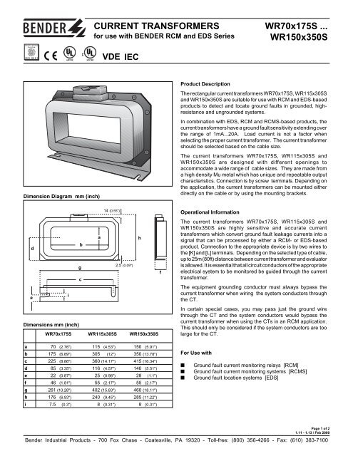
Dimension Diagram mm (inch)<br />
Product Description<br />
The rectangular current transformers WR70x175S, WR115x305S<br />
and WR150x350S are suitable for use with RCM and EDS-based<br />
products to detect and locate ground faults in grounded, highresistance<br />
and ungrounded systems.<br />
In combination with EDS, RCM and RCMS-based products, the<br />
current transformers have a ground fault sensitivity extending over<br />
the range of 1mA...20A. Load current is not a factor when<br />
selecting the proper current transformer. The current transformer<br />
should be selected based on the cable size.<br />
The current transformers WR70x175S, WR115x305S and<br />
WR150x350S are designed with different openings to<br />
accommodate a wide range of cable sizes. They are made from<br />
a high density Mu metal which has unique and repeatable output<br />
characteristics. Connection is by screw terminals. Depending on<br />
the application, the current transformers can be mounted either<br />
directly on the cable or by using the mounting brackets.<br />
14 (0.55")<br />
a<br />
h<br />
d<br />
b<br />
g<br />
2.5 (0.09")<br />
f<br />
c<br />
e<br />
i<br />
Dimensions mm (inch)<br />
WR70x175S WR115x305S WR150x350S<br />
Operational Information<br />
The current transformers WR70x175S, WR115x305S and<br />
WR150x350S are highly sensitive and accurate current<br />
transformers which convert ground fault leakage currents into a<br />
signal that can be processed by either a RCM- or EDS-based<br />
product. Connection to the appropriate device is by two wires to<br />
the [K] and [L] terminals. Depending on the selected type of cable,<br />
up to 25m (80ft) distance between current transformer and evaluator<br />
is allowed. It is essential that all circuit conductors of the appropriate<br />
electrical system to be monitored be guided through the current<br />
transformer.<br />
The equipment grounding conductor must always bypass the<br />
current transformer when wiring the system conductors through<br />
the CT.<br />
In certain special cases, you may pass just the ground wire<br />
through the CT and the system conductors would bypass the<br />
current transformer when using the CTs in an RCM application.<br />
This should only be considered if the system conductors are too<br />
large for the CT.<br />
a 70 (2.76") 115 (4.53") 150 (5.91")<br />
b 175 (6.89") 305 (12") 350 (13.78")<br />
c 225 (8.86") 360 (14.17") 415 (16.34")<br />
d 85 (3.35") 116 (4.57") 140 (5.51")<br />
e 22 (0.87") 25 (0.98") 28 (1.1")<br />
f 46 (1.81") 55 (2.17") 55 (2.17")<br />
g 261 (10.28") 402 (15.83") 460 (18.11")<br />
h 176 (6.93") 240 (9.45") 285 (11.22")<br />
i 7.5 (0.3") 8 (0.31") 8 (0.31")<br />
For Use with<br />
■ Ground fault current monitoring relays [RCM]<br />
■ Ground fault current monitoring systems [RCMS]<br />
■ Ground fault location systems [EDS]<br />
Page 1 of 2<br />
1.11 - 1.13 / Feb 2000<br />
<strong>Bender</strong> Industrial Products - 700 Fox Chase - Coatesville, PA 19320 - Toll-free: (800) 356-4266 - Fax: (610) 383-7100
Technical Data WR70x175S ... WR150x350S<br />
General Data:<br />
Rated burden<br />
180Ω<br />
Rated ground fault sensing current<br />
10A<br />
Continuous ground fault overload capacity<br />
20A<br />
Rated short-time thermal current (1 sec.)<br />
14 kA<br />
Nominal power<br />
500 mVA<br />
Frequency Range<br />
15Hz...400Hz<br />
Accuracy 99%<br />
Ambient temperature<br />
-10°C ... +50°C<br />
Flammability class<br />
UL94V-0<br />
Rated transformation ratio 600:1<br />
CT material high density Mu metal<br />
Testing:<br />
Rated insulation voltage acc. DIN VDE 0110 T.1 AC 630 V<br />
Rated impulse withstand voltage/<br />
contamination level<br />
6 kV/3<br />
BIL Rating<br />
2 kV<br />
Dielectric test voltage acc.<br />
DIN VDE 0435 T.303/IEC 255<br />
AC 3 kV<br />
Connections & Mounting:<br />
Length of the connecting leads<br />
Type of connection to the measuring transformer<br />
Single wires up to 3' (1 m)<br />
Twisted pair cable up to 30' (10 m)<br />
Shielded twisted pair cable up to 75' (25 m)<br />
Screw mounting #10<br />
Cable routing through the measuring transformer<br />
GND<br />
PE N L1 L2 L3 GND PE N L1 L2 L3<br />
L+ L-<br />
L1 L2 L3<br />
Safety Instructions<br />
The ground conductor should always bypass the current<br />
transformer.<br />
Avoiding interferences in case of high inrush currents<br />
Warning<br />
Electrical equipment shall only be installed by qualified<br />
personnel in consideration of the current safety regulations!<br />
Standards<br />
The current transformers WR 70x175S ... WR 150x350S<br />
correspond to DIN VDE 0414 and IEC 185, and are UL-listed,<br />
File #: E173157.<br />
Ordering Information<br />
Type<br />
Article No.<br />
WR 70x175S 911738<br />
WR 115x305S 911739<br />
WR 150x350S 911740<br />
Page 2 of 2<br />
1.11 - 1.14/ Feb 2000<br />
<strong>Bender</strong> Industrial Products - 700 Fox Chase - Coatesville, PA 19320 - Toll-free: (800) 356-4266 - Fax: (610) 383-7100


