

UG 140P NEW1 copy - Bender
UG 140P NEW1 copy - Bender
UG 140P NEW1 copy - Bender

Create successful ePaper yourself
Turn your PDF publications into a flip-book with our unique Google optimized e-Paper software.
GROUND FAULT MONITOR<br />
for Ungrounded DC Systems<br />
<strong>UG</strong><strong>140P</strong><br />
Quality System<br />
Certified<br />
ISO 9001<br />
VDE IEC<br />
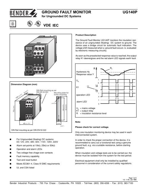
Product Description<br />
The Ground Fault Monitor <strong>UG</strong><strong>140P</strong> monitors the insulation resistance<br />
of an ungrounded (floating) DC system to ground. The<br />
device uses a bridge circuit for automatic fault indication. The<br />
voltage shift measured when a ground fault occurs is evaluated<br />
by electronic measuring circuitry.<br />
As soon as the preselected response value is reached, the output<br />
relay K1 deenergizes and the red alarm LED signals earth fault.<br />
R<br />
Hysteresis Hy<br />
Response value Y<br />
R F<br />
Dimension Diagram (mm)<br />
70 (2.76")<br />
105 (4.13")<br />
5 (0.2")<br />
DIN Rail mounting as per<br />
DIN EN 50 022 Mounting plate for<br />
screw mounting<br />
ø 4,5 (0.178")<br />
80 (3.15")<br />
90 (3.54")<br />
U N<br />
K1<br />
U N<br />
11<br />
operation LED<br />
alarm LED<br />
1<br />
0<br />
14<br />
12<br />
1<br />
= mains voltage<br />
K1 = output relay<br />
R = insulation resistance level<br />
0<br />
1<br />
0<br />
45 (1. 77")<br />
DIN Rail mounting as per DIN EN 50 022<br />
15,6<br />
(0.61")<br />
Note:<br />
Please check for correct voltage.<br />
Only one insulation monitoring device may be used in each<br />
interconnected system.<br />
■<br />
■<br />
■<br />
■<br />
■<br />
■<br />
■<br />
■<br />
For Ungrounded (floating) DC systems<br />
DC 12V, 24V, 48V, 60V, 110V, 125V, 220V<br />
Alarm set-points at 10kΩ, 25kΩ or 50kΩ<br />
Operation and alarm LEDs<br />
Two voltage-free chage-over contacts<br />
Fault memory capability<br />
Test and reset button<br />
Meets IEC801-4, Class III EMC requirements<br />
UL and CSA listed<br />
In order to check the proper connection of the device, it is<br />
recommeded to carry out a functional test using a genuine<br />
ground fault, e.g. via a suitable resistance, before starting<br />
operation.<br />
When insulation and voltage tests are to be carried out, the<br />
device must be isolated from the system for the test period.<br />
Electrical equipment shall only be installed by qualified<br />
personnel in consideration of the current safety regulations.<br />
Page 1 of 2<br />
1.2 - 1.1A / Jan 1995<br />
<strong>Bender</strong> Industrial Products - 700 Fox Chase - Coatesville, PA 19320 - Toll-free: (800) 356-4266 - Fax: (610) 383-7100
Technical Data <strong>UG</strong><strong>140P</strong><br />
Insulation<br />
Rated insulation voltage<br />
DC 300 V/AC 250 V<br />
Rated impulse voltage/ disturbance grade<br />
4kV/3<br />
Operation class<br />
continuous operation<br />
Monitored System<br />
Rated mains voltage U N DC 220, 125, 110, 60, 48, 24, 12 V<br />
Operating range<br />
0.8 ... 1.1 U N<br />
Supply voltage<br />
Supply voltage -<br />
Operating range -<br />
Self-consumption<br />
2.7 W<br />
Response values 110 ... 220 V 24 ... 60 V 12 V<br />
Response value R AN1 50 kΩ 25 kΩ 10 kΩ<br />
Response value R AN2<br />
Hysteresis -<br />
Response delay -<br />
Max. mains leakage capacitance 1 µF<br />
Adjustment by factory -<br />
Measuring circuit 220 V 12 V<br />
Measuring voltage U M - -<br />
Measuring current I M 2.2 mA 0.3 mA<br />
Internal DC resistance R i , 100 kΩ 40 kΩ<br />
Internal measuring resistance - -<br />
Impedance Z i , 60 Hz- -<br />
Max. admissible stray DC voltage -<br />
Outputs<br />
Meter output SKMP -<br />
Current output (max. load) -<br />
Terminal AK for coupling device -<br />
Alarm Relay<br />
Switching components<br />
2 voltage-free SPDT contacts<br />
Rated contact voltage<br />
AC 250 V/DC 300 V<br />
Rated current<br />
UC 5 A<br />
Break capacity AC 230 V, p.f. = 0.4<br />
AC 2 A<br />
Break capacity DC 110 V and L/R = 0.04 s<br />
DC 0.2 A<br />
Operating mode<br />
Normally Energized / De-energized<br />
Adjustment by factory<br />
Normally De-energized<br />
Testing<br />
Dielectric test: Test voltage<br />
2 kV<br />
Impulse voltage test acc. to IEC255-5<br />
class III<br />
Electrical disturbance test acc. to IEC255-5<br />
class III<br />
Elec. fast transient burst acc. to IEC801-4 severity degree 2<br />
Shock resistance acc. IEC68-2-27<br />
15g / 11sec<br />
Vibration strength acc. to IEC68-2-6 10...15kHz / 0.15mm - 2g<br />
Bumping acc. to IEC68-2-29<br />
40g / 11msec<br />
Environmental Conditions<br />
Ambient temperature, during operation -10°C ... +55°C<br />
Storage temperature range<br />
-40°C ... +70°C<br />
General Data<br />
Type of connection<br />
screw terminals<br />
Wire size, solid<br />
14 AWG<br />
Wire size, stranded with end sleeve<br />
16 AWG<br />
Mounting DIN rail or screw (#990 056)<br />
Weight<br />
1 lb<br />
Wiring diagram<br />
Legend to Wiring Diagram<br />
If the fault indication is to be stored, the terminals A2-LT2<br />
must be linked by a bridge or an external reset button.<br />
K1<br />
DC<br />
Betriebs-/<br />
operation-LED<br />
Melde-/<br />
indicating-LED<br />
Prüfen / test<br />
Löschen / reset<br />
alarm output relay<br />
Ordering Guide<br />
A1<br />
ext. Prüftaste/<br />
test button<br />
A1 A2 LT2<br />
PT1PT2<br />
A2<br />
11 12 14<br />
21 22 24<br />
ext. Löschtaste/<br />
reset button<br />
PT1 PT2 A2 LT2<br />
Type Rated mains voltage Art. No.<br />
U N<br />
DC 12 V 916 410<br />
DC 24 V 916 382<br />
<strong>UG</strong><strong>140P</strong> DC 48 V 916 304<br />
DC 60 V 916 259<br />
DC 110 V 916 612<br />
DC 125 V 916 613<br />
DC 220 V 916 170<br />
K1<br />
12<br />
11 21<br />
14<br />
L+<br />
L-<br />
PE<br />
22 24<br />
Page 2 of 2<br />
1.2 - 1.2A / Jan 1995<br />
<strong>Bender</strong> Industrial Products - 700 Fox Chase - Coatesville, PA 19320 - Toll-free: (800) 356-4266 - Fax: (610) 383-7100


