

Technical data Insulation fault location system for ... - Bender
Technical data Insulation fault location system for ... - Bender
Technical data Insulation fault location system for ... - Bender

You also want an ePaper? Increase the reach of your titles
YUMPU automatically turns print PDFs into web optimized ePapers that Google loves.
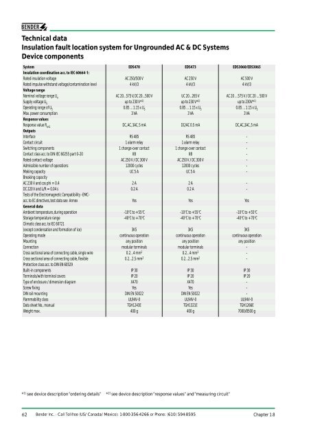
<strong>Technical</strong> <strong>data</strong><br />
<strong>Insulation</strong> <strong>fault</strong> <strong>location</strong> <strong>system</strong> <strong>for</strong> Ungrounded AC & DC Systems<br />
Device components<br />
System EDS470 EDS473 EDS3060/EDS3065<br />
<strong>Insulation</strong> coordination acc. to IEC 60664-1:<br />
Rated insulation voltage AC 250/500 V AC 250 V AC 500 V<br />
Rated impulse withstand voltage/contamination level 4 kV/3 4 kV/3 4 kV/3<br />
Voltage range<br />
Nominal voltage range U n<br />
AC 20...575 V, DC 20...500 V UC 20...265 V AC 20 ... 575 V / DC 20 ... 500 V<br />
Supply voltage U S<br />
up to 230 V* 1) up to 230 V* 1) up to 230V* 1)<br />
Operating range of U S<br />
0.85 ... 1.15 x U S<br />
0.85 ... 1.15 x U S<br />
0.85 ... 1.15 x U S<br />
Max. power consumption 3 VA 3 VA 3 VA<br />
Response values<br />
Response value R an1<br />
DC, AC, 3AC, 5 mA DC/AC 0.5 mA DC,AC,3AC, 5 mA<br />
Outputs<br />
Interface RS 485 RS 485 -<br />
Contact circuit 1 alarm relay 1 alarm relay -<br />
Switching components 1 change-over contact 1 change-over contact -<br />
Contact class acc. to DIN IEC 60255 part 0-20 IIB IIB -<br />
Rated contact voltage AC 250 V / DC 300 V AC 250 V / DC 300 V -<br />
Admissible number of operations 12000 cycles 12000 cycles -<br />
Making capacity UC 5 A UC 5 A -<br />
Breaking capacity<br />
AC 230 V and cos phi = 0.4 2 A 2 A -<br />
DC 220 V and L/R = 0.04 s 0.2 A 0.2 A -<br />
Tests of the Electromagnetic Compatibility -EMCacc.<br />
to EC directives, test <strong>data</strong> see Annex Yes Yes Yes<br />
General <strong>data</strong><br />
Ambient temperature, during operation -10°C to +55°C -10°C to +55°C -10°C to +55°C<br />
Storage temperature range -40°C to +70°C -40°C to +70°C -40°C to +70°C<br />
Climatic class acc. to IEC 60721<br />
(except condensation and <strong>for</strong>mation of ice) 3K5 3K5 3K5<br />
Operating mode continuous operation continuous operation continuous operation<br />
Mounting any position any position any position<br />
Connection modular terminals modular terminals -<br />
Cross sectional area of connecting cable, single wire 0.2...4 mm 2 0.2...4 mm 2 -<br />
Cross sectional area of connecting cable, flexible 0.2...2.5 mm 2 0.2...2.5 mm 2 -<br />
Protection class acc. to DIN EN 60529<br />
Built-in components IP 30 IP 30 IP 30<br />
Terminals/with terminal covers IP 20 IP 20 IP 20<br />
Type of enclosure / dimension diagram X470 X470 -<br />
Screw fixing Yes Yes -<br />
DIN rail mounting DIN EN 50022 DIN EN 50022 -<br />
Flammability class UL94V-0 UL94V-0 UL94V-0<br />
Data sheet No., manual TGH1243E TGH1321E TGH1266E<br />
Weight max. 400 g 400 g 7000/8500 g<br />
* 1) see device description “ordering details“ * 2) see device description “response values“ and “measuring circuit“<br />
62 <strong>Bender</strong> Inc. - Call Toll-free (US/Canada/Mexico): 1-800-356-4266 or Phone: (610) 594-8595 Chapter 1.8
Chapter 1.8<br />
Device type EDS3360/EDS3365 EDS165 EDS165-3<br />
<strong>Insulation</strong> coordination acc. to IEC 60664-1:<br />
Rated insulation voltage AC 250 V - -<br />
Rated impulse withstand voltage/contamination level 4 kV/3 - -<br />
Voltage range<br />
Nominal voltage range U n<br />
AC 20...265 V * 1) - -<br />
Supply voltage U S<br />
up to AC 230 V * 1) DC 6 V (battery) DC 6 V (battery)<br />
Operating range of U S<br />
0.85...1.15 x US DC 4.2...6.2 V DC 4.2 ... 6.2 V<br />
Max. power consumption 3 VA 0.6 W 0.6 W<br />
Response values<br />
Response value R an1<br />
DC/AC 0.5 mA - -<br />
Outputs<br />
Interface - RS 232 RS 232<br />
Contact circuit - - -<br />
Switching components - - -<br />
Contact class acc. to DIN IEC 60255 part 0-20 - - -<br />
Rated contact voltage - - -<br />
Admissible number of operations - - -<br />
Making capacity - - -<br />
Breaking capacity<br />
AC 230 V and cos phi = 0.4 - - -<br />
DC 220 V and L/R = 0.04 s - - -<br />
Tests of the Electromagnetic Compatibility -EMCacc.<br />
to EC directives, test <strong>data</strong> see Annex Yes Yes Yes<br />
General <strong>data</strong><br />
Ambient temperature, during operation -10°C to +55°C -10°C to +55°C -10°C to +55°C<br />
Storage temperature range -40°C to +70°C -40°C to +70°C -40°C to +70°C<br />
Climatic class acc. to IEC 60721<br />
(except condensation and <strong>for</strong>mation of ice) 3K5 - -<br />
Operating mode continuous operation - -<br />
Mounting any position - -<br />
Connection - - -<br />
Cross sectional area of connecting cable, single wire - - -<br />
Cross sectional area of connecting cable, flexible - - -<br />
Protection class acc. to DIN EN 60529<br />
Built-in components IP 30 IP 40 IP40<br />
Terminals/with terminal covers IP 20 IP 30 IP30<br />
Type of enclosure/dimension diagram - portable enclosure portable enclosure<br />
Screw fixing - - -<br />
DIN rail mounting - - -<br />
Flammability class UL94V-0 - -<br />
<strong>Technical</strong> manual TGH 1320E TGH 1266E TGH 1320E<br />
Weight max. 7000/8500 g 370 g 370 g<br />
1.8<br />
* 1) see device description “ordering details“ * 2) see device description “response values“ and “measuring circuit“<br />
Chapter 1.8<br />
Main catalogue part 1 / <strong>Insulation</strong> monitoring<br />
63
PGH471<br />
ON<br />
A3 A1<br />
SLAVE ADDRESS + 110<br />
START<br />
25mA A3 A2 A1 A0 SLAVE RS485 STOP<br />
1<br />
0<br />
10mA<br />
MASTER<br />
GENERATOR<br />
A3 A1<br />
6 0 V CAT I<br />
1 0 mA / 0,1 mA ~<br />
PSA3352<br />
EDS470 <strong>system</strong><br />
EDS473 <strong>system</strong><br />
<strong>Insulation</strong> <strong>fault</strong> <strong>location</strong> <strong>system</strong> <strong>for</strong><br />
Ungrounded (IT) AC and DC <strong>system</strong>s<br />
General description<br />
The EDS insulation <strong>fault</strong> <strong>location</strong> <strong>system</strong> is<br />
<strong>for</strong> ungrounded (IT) <strong>system</strong>s. This allows<br />
insulation <strong>fault</strong>s to be detected fast and<br />
reliably during operation.<br />
Advantages of the EDS <strong>system</strong><br />
• <strong>Insulation</strong> <strong>fault</strong> <strong>location</strong> during<br />
operation, no interruption to<br />
operation;<br />
• Reduction in costs because of<br />
reduced production stoppages<br />
• Reduced maintenance costs due<br />
to fast localization of insulation <strong>fault</strong>s<br />
• Improved preventive and scheduled<br />
maintenance<br />
• Higher availability of power supply<br />
thanks to diminished interruption to<br />
operation.<br />
Basic components<br />
An EDS470 <strong>system</strong> consists of:<br />
• control and indicating device PRC470,<br />
• test device PGH471,<br />
• 1 to 30 evaluators EDS470-12,<br />
• corresponding number of<br />
measuring current trans<strong>for</strong>mers<br />
of the W1-S35...W5-S210, WR<br />
or WS... series.<br />
System basic components<br />
A1 A2 11 14 L1 L2 L3<br />
A B GND IN1 IN2 IN3<br />
E<br />
Basic components<br />
An EDS473 <strong>system</strong> consists of:<br />
• control and indicating device PRC470,<br />
• test device PGH473/PGH474,<br />
• 1 to 30 evaluators EDS473-12,<br />
• corresponding number of<br />
measuring current trans<strong>for</strong>mers<br />
of the W1-35/8000, W08/8000,<br />
or WS50x80/8000 series.<br />
I∆s<br />
System characteristics<br />
• Universal <strong>system</strong> concept <strong>for</strong> all<br />
ungrounded (IT) <strong>system</strong>s<br />
I∆s<br />
ME SZANGE / CLAMP ON PROBE<br />
Datenbla t / Datash et : TGH1320<br />
Durchme ser / Diameter : 52 m<br />
Art.-Nr. / Art.-no. : B 980 695<br />
max. 1 A<br />
- EDS470, AC 20...575 V/DC 20...500 V<br />
(AC 20...790 V/DC 20...960 V<br />
with AGE470)<br />
- EDS473, AC/DC 20...265 V<br />
• Modular construction <strong>for</strong> individual<br />
adaptation to the electrical<br />
installation;<br />
• Measuring current trans<strong>for</strong>mers in<br />
various sizes and constructional<br />
designs;<br />
• Monitors and controls up to 360 CT<br />
circuits;<br />
• In<strong>for</strong>mation exchange between the<br />
individual devices via the RS485<br />
interface (two-wire);<br />
• Indication of the <strong>fault</strong>y circuit;<br />
• Indication of the test current flowing<br />
in each circuit.<br />
64 <strong>Bender</strong> Inc. - Call Toll-free (US/Canada/Mexico): 1-800-356-4266 or Phone: (610) 594-8595 Chapter 1.8
Function<br />
The EDS <strong>system</strong> works together with an insulation monitoring device that monitors the<br />
insulation resistance of the entire <strong>system</strong>. When an insulation <strong>fault</strong> is signalled by the<br />
insulation monitoring device, the EDS <strong>system</strong> starts <strong>fault</strong> <strong>location</strong> (automatically or<br />
manually) in order to determine the <strong>fault</strong>y circuit of the (IT) ungrounded <strong>system</strong>.<br />
When a first <strong>fault</strong> occurs in ungrounded <strong>system</strong>s, a <strong>fault</strong> current flows which is essentially<br />
determined by the <strong>system</strong> leakage capacitances and the insulation resistance. The basic<br />
concept in <strong>fault</strong> <strong>location</strong> is there<strong>for</strong>e to close the <strong>fault</strong> current circuit <strong>for</strong> a short period<br />
over a current-limiting resistance. As a result of this principle, the <strong>system</strong> voltage itself<br />
drives a test current which results in a signal that can be evaluated.<br />
The test current is generated periodically by the PGH471/473/474 test device. The test<br />
current is limited in amplitude and time. As this happens, the <strong>system</strong> conductors are<br />
connected alternately to ground (PE) via a current-limiting resistance. The test current pulse<br />
flows from the test device via the live conductors, taking the shortest path to the <strong>location</strong><br />
of the insulation <strong>fault</strong>. From there it flows via the insulation <strong>fault</strong> and the ground conductor<br />
back to the test device. This current pulse is then detected by the measuring current<br />
trans<strong>for</strong>mers located in the insulation <strong>fault</strong> path, and is evaluated by the connected<br />
insulation <strong>fault</strong> evaluator.<br />
Sophisticated evaluation method and filtering prevent false alarms <strong>for</strong> ground <strong>fault</strong> currents<br />
up to 10 A/(1 A). The measuring current trans<strong>for</strong>mers are used as ground <strong>fault</strong> current<br />
trans<strong>for</strong>mers, i.e. the ground (PE) conductor is not led through the current trans<strong>for</strong>mer.<br />
The response value is determined by the sensitivity of the insulation <strong>fault</strong> evaluators<br />
EDS470-12/EDS473-12 or EDS165/165-3. The response value is 5 mA as arithmetic mean<br />
value in DC as well as in AC and 3 AC <strong>system</strong>s (EDS470) respectively 0.5 mA (EDS473).<br />
1.8<br />
Chapter 1.8<br />
Main catalogue part 1 / <strong>Insulation</strong> monitoring<br />
65
Control and indicating device<br />
PRC470<br />
The control and indicating device PRC470<br />
per<strong>for</strong>ms the central control and<br />
monitoring function in EDS <strong>system</strong>s. The<br />
in<strong>for</strong>mation exchange between the<br />
individual components of the EDS470<br />
<strong>system</strong> takes place via the RS485 interface.<br />
Apart from the control functions and the<br />
extended scanning possibilities, the<br />
PRC470 is used to setup the EDS470<br />
<strong>system</strong> to different <strong>system</strong> parameters.<br />
The PRC470 also may be set to operation<br />
with <strong>system</strong> interferences, e.g. caused by<br />
frequency converters with low-frequency<br />
leakage currents or switch gear and<br />
controls producing transient leakage<br />
currents. Additional problems may arise<br />
through EMC suppression capacitors<br />
which are more and more used to comply<br />
with the EMC requirements.<br />
Essential func tions ar e<br />
• Control and synchronization of the<br />
test cycle of the PGH47. test device ;<br />
• Indication via LC display;<br />
• Display of the respective test current<br />
in each CT circuit;<br />
• Display of the connections between<br />
current trans<strong>for</strong>mer and insulation<br />
<strong>fault</strong> evaluator EDS470-12/EDS473-12;<br />
• Test function <strong>for</strong> testing all devices<br />
connected;<br />
• Setting of the operating principle <strong>for</strong><br />
each insulation <strong>fault</strong> evaluator;<br />
• Setting of the different measuring<br />
current trans<strong>for</strong>mer types used;<br />
• Setting via software menus;<br />
• Scanning of individual CT<br />
circuits.<br />
<strong>Insulation</strong> <strong>fault</strong> test device<br />
PGH471/473/474<br />
After detecting the insulation <strong>fault</strong> through<br />
the insulation monitoring device, insulation<br />
<strong>fault</strong> <strong>location</strong> is started via the<br />
control and indicating device PRC470.<br />
Once the insulation <strong>fault</strong> test device<br />
PGH471 is started, it produces a defined<br />
test current signal. The <strong>system</strong> voltage<br />
drives the test current. The value of the<br />
test current depends on insulation<br />
resistance, leakage capacitance and the<br />
<strong>system</strong> voltage. The test current is limited<br />
to max. 25 mA/(2.5 mA). The maximum<br />
test current can be limited to 10 mA/<br />
(1 mA) via a DIP switch. This limitation is<br />
recommended when using the <strong>system</strong> in<br />
control <strong>system</strong>s with sensitive relays or<br />
SPS.<br />
If the PGH471/473/474 is active, both<br />
cycle LEDs light up alternately during the<br />
respective cycle.<br />
<strong>Insulation</strong> <strong>fault</strong> evaluator<br />
EDS470-12, EDS473-12<br />
The insulation <strong>fault</strong> evaluator EDS470-12/<br />
EDS473-12 is controlled by means of a<br />
microcontroller. Together with the<br />
measuring current trans<strong>for</strong>mers it is used<br />
to evaluate test current signals generated<br />
by the insulation <strong>fault</strong> test device.<br />
The device subsequently evaluates the<br />
signals from all connected measuring<br />
current trans<strong>for</strong>mers. If the <strong>fault</strong> current<br />
detected by a measuring current<br />
trans<strong>for</strong>mer exceeds the response value,<br />
the respective alarm LED of the LED line<br />
and the alarm LED light up and the alarm<br />
relay switches. The alarm relay outputs a<br />
common alarm <strong>for</strong> all measuring<br />
channels.<br />
Up to 12 measuring current trans<strong>for</strong>mers<br />
can be connected to one insulation <strong>fault</strong><br />
evaluator EDS470-12/EDS473-12.<br />
Connection l of the measuring current<br />
trans<strong>for</strong>mers must be wired in a star<br />
connection to terminal l of the evaluator<br />
EDS470-12/EDS473-12.<br />
All settings within an EDS <strong>system</strong> are<br />
carried out at the control and indicating<br />
device PRC470.<br />
66 <strong>Bender</strong> Inc. - Call Toll-free (US/Canada/Mexico): 1-800-356-4266 or Phone: (610) 594-8595 Chapter 1.8
EDS470 <strong>system</strong><br />
EDS473 <strong>system</strong><br />
<strong>Insulation</strong> <strong>fault</strong> <strong>location</strong> <strong>system</strong> <strong>for</strong><br />
Ungrounded (IT) AC and DC <strong>system</strong>s<br />
Coupling device AGE470<br />
The EDS <strong>system</strong> is suitable <strong>for</strong> monitoring<br />
and scanning ungrounded (IT) <strong>system</strong>s of<br />
AC 45....65 Hz, 20...575 V and DC 20...500V.<br />
The voltage range of AC <strong>system</strong>s can be<br />
extended to AC 790 V, and that of DC<br />
<strong>system</strong>s to DC 960 V by means of the<br />
coupling device AGE470.<br />
Connection between the insulation <strong>fault</strong><br />
test device PGH471 and coupling device<br />
AGE470.<br />
Measuring current trans<strong>for</strong>mers <strong>for</strong> EDS <strong>system</strong>s<br />
To meet the requirements of an electrical installation, different types of measuring<br />
current trans<strong>for</strong>mers are available <strong>for</strong> EDS insulation <strong>fault</strong> <strong>location</strong> <strong>system</strong>s. Measuring<br />
current trans<strong>for</strong>mers which are commercially available are not suitable <strong>for</strong> the EDS <strong>system</strong><br />
and must not be used.<br />
Suitable measuring current trans<strong>for</strong>mers are listed in the table below.<br />
All measuring current trans<strong>for</strong>mers listed in the table are highly sensitive and convert<br />
even very small residual currents into evaluable signals. Connection to the insulation <strong>fault</strong><br />
evaluator is carried out via two connecting leads. When installing please make sure that<br />
all current-carrying leads of the respective sub-circuit are passed through the current<br />
trans<strong>for</strong>mer. Te ground conductor must not be passed through the current trans<strong>for</strong>mer.<br />
Measuring current trans<strong>for</strong>mers <strong>for</strong> EDS <strong>system</strong>s<br />
Type Internal Design Setting Connection System<br />
diameter (mm)<br />
PRC470 menu<br />
W0-S15 15 circular standard 6.3 mm Faston EDS470<br />
W1-S35 35 circular standard screw terminals<br />
W2-S70 70 circular standard screw terminals<br />
W3-S105 105 circular standard screw terminals<br />
W4-S140 140 circular standard screw terminals<br />
W5-S210 210 circular standard screw terminals<br />
WR70x175S 70x175 rectangular standard screw terminals EDS470<br />
WR115x305S 115x305 rectangular standard screw terminals<br />
WR150x350S 150x350 rectangular standard screw terminals<br />
WS50x80S 50x80 split-core split-core screw terminals EDS470<br />
WS80x80S 80x80 split-core split-core screw terminals<br />
WS80x120S 80x120 split-core split-core screw terminals<br />
WS80x160S 80x160 split-core split-core screw terminals<br />
W1-35/8000 35 circular standard screw terminals EDS473<br />
W08/8000 8 circular standard 0.5 mm 2 x 2 m<br />
WS50x80/8000 50x80 split-core split-core screw terminals<br />
<strong>Technical</strong> <strong>data</strong> EDS470 EDS473<br />
Rated insulation voltage: AC 720 V AC 720 V<br />
Rated impulse withstand voltage: 3 kV 3 kV<br />
Contamination level: 3 3<br />
Dielectric test acc. to IEC 6044-1: AC 3 kV AC 3 kV<br />
Rated trans<strong>for</strong>mation ratio: 600:1 8000:1<br />
Rated burden: 180 Ω 24 kΩ<br />
Rated primary current: 10 A 1 A<br />
Continuous overload capacity: 100 A 6 A<br />
Rated short-time thermal current 1 (sec).: 14 kA/1s 0.75 kA/1s<br />
Nominal power: 50 mVA 0.375 mVA<br />
Accuracy class: 5 5<br />
Ambient temperature: -10°C ... + 55°C -10°C ... + 55°C<br />
Flammability class: UL94V-0 UL94V-0<br />
Length of the connecting leads<br />
Single wires 0.75 mm 2 up to 1 m up to 1 m<br />
Single wires 0.75 mm 2 , twisted up to 10 m up to 10 m<br />
Shielded cable 0.75 mm 2 (shield to terminal l) up to 25 m up to 25 m<br />
1.8<br />
Chapter 1.8<br />
Main catalogue part 1 / <strong>Insulation</strong> monitoring<br />
67
Measuring current trans<strong>for</strong>mer<br />
W0-S15<br />
Measuring current trans<strong>for</strong>mer<br />
W08/8000<br />
Measuring current trans<strong>for</strong>mer<br />
series W1-S35 ... W5-S210, W1-35/8000<br />
Split-core measuring current trans<strong>for</strong>mer<br />
series WS..., WS 50x80/8000<br />
Measuring current trans<strong>for</strong>mer<br />
series WR...<br />
Dimensions (in mm) and weights (in kg)<br />
Type A B C<br />
Type A B C D<br />
Type a b c d e<br />
W1-S35 100 79 26<br />
W1-35/8000 100 79 26<br />
W2-S70 130 110 32<br />
W3-S105 170 146 38<br />
W4-S140 220 196 48.5<br />
W5-S210 299 284 69<br />
Type D øE Weight<br />
W1-S35 48.5 35 0.25 kg<br />
W1-35/8000 48.5 35 0.25 kg<br />
W2-S70 66 70 0.38 kg<br />
W3-S105 94 105 0.70 kg<br />
W4-S140 123 140 1.50 kg<br />
W5-S210 161 210 2.50 kg<br />
WS 50x80S 50 80 78 114<br />
WS 50x80/8000 50 80 78 114<br />
WS 80x80S 80 80 108 144<br />
WS 80x120S 80 120 105 144<br />
WS 80 x 160S 80 160 108 144<br />
Type E Weight<br />
WS 50x80S 145 0.90 kg<br />
WS 50x80/8000 145 0.90 kg<br />
WS 80x80S 145 1.05 kg<br />
WS 80x120S 185 1.25 kg<br />
WS 80 x 160S 225 3.50 kg<br />
WR 70 x 175 S 70 175 225 85 22<br />
WR 115 x 305 S 115 305 360 116 25<br />
WR 150 x 350 S 150 350 415 140 28<br />
Type f g h i Weight<br />
WR 70 x 175 S 46 261 176 7.7 2.40 kg<br />
WR 115 x 305 S 55 402 240 8 5.45 kg<br />
WR 150 x 350 S 55 460 285 8 7.40 kg<br />
68 <strong>Bender</strong> Inc. - Call Toll-free (US/Canada/Mexico): 1-800-356-4266 or Phone: (610) 594-8595 Chapter 1.8
EDS470 / EDS473<br />
Construction of an EDS <strong>system</strong><br />
The example of an interconnection<br />
diagram below shows a central insulation<br />
monitoring device IRDH265 monitoring, a<br />
three-phase <strong>system</strong>. If the insulation<br />
value falls below the preset response<br />
value, the PGH471 will be activated by the<br />
insulation monitoring device via the relay<br />
contacts 21/24. The insulation <strong>fault</strong> test<br />
device PGH471 is connected to the<br />
insulation <strong>fault</strong> evaluator EDS470-12 and<br />
the control and indicating device PRC470<br />
via the RS485 interface (terminals A and B).<br />
After the PGH471 is activated from the<br />
PRC470 via the interface, the EDS470-12<br />
starts scanning the connected measuring<br />
current trans<strong>for</strong>mers. The diagram<br />
opposite shows three connected<br />
measuring current trans<strong>for</strong>mers. The<br />
RS485 serial interface has to be<br />
terminated at both ends with a resistor of<br />
120 Ω.<br />
The common connection I to the measuring<br />
current trans<strong>for</strong>mers must be
EDS470 <strong>system</strong><br />
Example of an interconnection diagram of an EDS <strong>system</strong> with SMO480-12, DI-1 and FTC1500<br />
Construction of an EDS <strong>system</strong> in combination with SMO480-12, DI-1 and FTC1500<br />
The interconnection diagram above<br />
illustrates an extended EDS <strong>system</strong>. The<br />
following components have been<br />
integrated into the classical EDS circuit:<br />
- SMO480-12<br />
(signal converter)<br />
- DI-1<br />
(RS485 repeater)<br />
- FTC1500<br />
(protocol converter)<br />
The SMO480-12 signal converter<br />
converts serial in<strong>for</strong>mation from <strong>Bender</strong><br />
evaluators into relay signals. There is one<br />
relay available <strong>for</strong> each of the measuring<br />
channels of the evaluators. The SMO480-<br />
12 signal converter allows <strong>fault</strong>y circuits of<br />
the <strong>system</strong> to be switched off in an<br />
insulation <strong>fault</strong> <strong>location</strong> <strong>system</strong>. In this<br />
way, a failure of the entire electrical<br />
<strong>system</strong> can be prevented. The RS485<br />
repeater DI-1 amplifies the signals of the<br />
RS485 interfaces. In EDS <strong>system</strong>s with a lot<br />
of circuits to be monitored, the maximum<br />
bus length of 1200 m often is not<br />
sufficient. Here the use of a DI-1 can<br />
extend the RS485 bus length to additional<br />
1200 m (4000 ft). As a side effect the<br />
number of the maximum possible bus<br />
nodes can be increased by 32.<br />
The EDS <strong>system</strong> (insulation <strong>fault</strong> <strong>location</strong><br />
<strong>system</strong>) communicates via the RS485<br />
interface using the BENDER BMS protocol.<br />
The protocol converter FTC1500 is a<br />
communication bridge between a RS485<br />
interface using the BENDER BMS protocol<br />
and an interface using the JBUS/MODBUS<br />
protocol, that allows the EDS <strong>system</strong> to be<br />
integrated into the JBUS/MODBUS<br />
environment.<br />
70 <strong>Bender</strong> Inc. - Call Toll-free (US/Canada/Mexico): 1-800-356-4266 or Phone: (610) 594-8595 Chapter 1.8
EDS473 <strong>system</strong><br />
Example of an interconnection diagram of an EDS473 <strong>system</strong><br />
1.8<br />
Chapter 1.8<br />
Main catalogue part 1 / <strong>Insulation</strong> monitoring<br />
71
EDS470 /EDS473<br />
<strong>Technical</strong> <strong>data</strong><br />
EDS470 <strong>system</strong><br />
EDS473 <strong>system</strong><br />
Components: PRC470, PGH471 PRC470, PGH473<br />
AGE470, EDS470-12<br />
EDS473-12<br />
SMO480-12, DI-1<br />
SMO480-12<br />
FTC-1500<br />
DI-1, FTC1500<br />
including E-version <strong>for</strong> 60 evaluators<br />
and 39 test devices<br />
Measuring current trans<strong>for</strong>mers W..., WR..., WS..., W1-35/8000; WS50 x 80/8000<br />
Portable <strong>system</strong>s EDS3065 and EDS3060 including EDS3360 and EDS3365 including<br />
PGH185; EDS165;PSA3020<br />
PGH183; EDS165-3, PSA3320<br />
PSA3052 and PSA3165<br />
and PSA3352<br />
Max. test current 25 / 10 mA 2.5 / 1 mA<br />
Response value 5 mA 0.5 mA<br />
<strong>Insulation</strong> resistance low response value higher response value (x10)<br />
Max. <strong>system</strong> leakage capacitance 20000 µFV (C e<br />
x U n<br />
) 300 µFV (C e<br />
x U n<br />
)<br />
EDS470 or EDS473 <br />
Selection EDS470 <strong>system</strong> EDS473 <strong>system</strong><br />
according to <strong>system</strong> voltage AC 20 -575 V AC 20 - 265 V<br />
DC 20 - 504 V<br />
DC 20 - 308 V<br />
including AGE470: AC 20...790 V/DC 20...960 V<br />
according to application<br />
extended ungrounded (IT) <strong>system</strong>s<br />
<strong>system</strong>s with variable-speed drives<br />
<strong>system</strong>s with electrical interferences<br />
auxiliary circuits<br />
diode-decoupled control circuits<br />
according to residual current max. 10A max. 1A<br />
72 <strong>Bender</strong> Inc. - Call Toll-free (US/Canada/Mexico): 1-800-356-4266 or Phone: (610) 594-8595<br />
Chapter 1.8
PGH183<br />
AC/DC<br />
System extensions, accessories<br />
The portable insulation <strong>fault</strong> evaluator<br />
EDS165-3 represents an ideal<br />
complement to the EDS <strong>system</strong> where<br />
EDS165 is suitable <strong>for</strong> EDS470 <strong>system</strong>s<br />
and EDS165-3 <strong>for</strong> EDS473 <strong>system</strong>s.<br />
The respective device can be used to track<br />
the <strong>fault</strong> <strong>location</strong> or to check additional<br />
subcircuits manually.<br />
The EDS165-3 is used in combination with<br />
current clamps.It detects the test current<br />
signal of the insulation <strong>fault</strong> test device<br />
PGH47. and works well with an existing<br />
EDS 47. <strong>system</strong>.<br />
The EDS165-3 is supplied via batteries. The<br />
operation and settings are carried out by<br />
means of the function keys and the LC<br />
display.<br />
Three current clamps are suitable <strong>for</strong> the<br />
EDS470 <strong>system</strong>. These are PSA3020 (with<br />
an internal diameter of 20 mm), PSA3052<br />
with an internal diameter of 52 mm and<br />
PSA3165 (with an internal diameter of<br />
100 mm).<br />
The current clamps PSA3320 with an<br />
internal diameter of 20 mm and PSA<br />
3352 with an internal diameter of 52<br />
mm are suitable <strong>for</strong> the EDS473 <strong>system</strong>.<br />
The clearly legible LC display indicates the<br />
actual test current flowing in the<br />
respective circuit and indicates if the<br />
alarm value has been exceeded.<br />
Furthermore it indicates which current<br />
clamp has been selected, the battery<br />
charge, the selected <strong>system</strong> frequency, and<br />
the mode of the buzzer.<br />
I∆s = 8 mA<br />
ALARM<br />
50Hz ( )<br />
The EDS165(-3) in combination with any<br />
current clamp can be used as a portable<br />
residual current monitor in grounded and<br />
high-resistance grounded. The operating<br />
mode can be changed by means of a<br />
selector.<br />
For detailed in<strong>for</strong>mation about portable<br />
insulation <strong>fault</strong> <strong>location</strong> refer to the<br />
technical manuals EDS3060 and EDS3065<br />
respectively EDS3360 and EDS3365.<br />
<strong>Insulation</strong> <strong>fault</strong> test device PGH185/PGH183<br />
The insulation <strong>fault</strong> test device PGH185/<br />
PGH183 is used to generate a defined test<br />
current<br />
which is generated there<strong>for</strong>e depends on<br />
the value of the insulation <strong>fault</strong> that is<br />
present, the leakage capacitance and on<br />
the <strong>system</strong> voltage. The test current is<br />
limited to a maximum of 25 mA/2.5 mA<br />
respectively max. 10 mA/ 1 mA depending<br />
on the switch position of the Imax switch.<br />
The test current flows from the <strong>system</strong> via<br />
the PGH185/PGH183 and then through<br />
the ground conductor (PE) and the<br />
insulation <strong>fault</strong>(s) back to the <strong>system</strong>. The<br />
test current signal is sensed by the current<br />
clamps or measuring current trans<strong>for</strong>mers<br />
located in the <strong>fault</strong> current circuit , and the<br />
<strong>fault</strong>y circuits are indicated by the<br />
insulation <strong>fault</strong> test device EDS165(-3)<br />
whenever the threshold of 5/0.5 mA is<br />
exceeded.<br />
1.8<br />
signal. It is applied in <strong>system</strong>s which do<br />
not include a permanently installed EDS<br />
<strong>system</strong>. <strong>Insulation</strong> <strong>fault</strong> <strong>location</strong> is carried<br />
out by means of the insulation <strong>fault</strong><br />
evaluators EDS165(-3) and the respective<br />
current clamps. The PGH185/PGH183 is a<br />
component of the EDS3065 respectively<br />
EDS3365.<br />
After switching on the PGH18. generates<br />
a defined test current signal. The voltage<br />
present in the <strong>system</strong> is used to drive the<br />
test current. The value of the test current<br />
100mA<br />
Us<br />
ON<br />
ON<br />
L1(+)<br />
2,5mA<br />
Imax<br />
1 mA<br />
L2(-)<br />
L3<br />
Chapter 1.8<br />
Main catalogue part 1 / <strong>Insulation</strong> monitoring<br />
73
System components at a glance<br />
The primary function of the EDS3.6. is that<br />
of an insulation <strong>fault</strong> <strong>location</strong> <strong>system</strong> in (IT)<br />
ungrounded <strong>system</strong>s. The components of<br />
the EDS3.6. are used in combination <strong>for</strong><br />
that purpose.<br />
<strong>Insulation</strong> <strong>fault</strong> test device PGH185/183<br />
Current clamp PSA3020<br />
Current clamp PSA3320<br />
Current clamp PSA3052<br />
Current clamp PSA3352<br />
<strong>Insulation</strong> <strong>fault</strong> evaluator EDS165(-3)<br />
Aluminium case with carrying belt<br />
Not illustrated:<br />
power supply cord (with plug <strong>for</strong> cold conditions) <strong>for</strong> the insulation <strong>fault</strong> test device PGH183;<br />
safety measuring leads 3 x black and 1x green/yellow;<br />
safety claw grip to connect the PGH18. with the <strong>system</strong> conductors and the equipment grounding conductor;<br />
BNC adapter unit/banana plug to connect measuring current trans<strong>for</strong>mers;<br />
banana plug;<br />
battery charging set <strong>for</strong> EDS165(-3).<br />
74 <strong>Bender</strong> Inc. - Call Toll-free (US/Canada/Mexico): 1-800-356-4266 or Phone: (610) 594-8595<br />
Chapter 1.8
Components and technical <strong>data</strong> of the EDS3.6. <strong>system</strong>s <strong>for</strong> ungrounded (IT) <strong>system</strong>s<br />
EDS3060 EDS3065 EDS3360 EDS3365<br />
Components Aluminium case Aluminium case Aluminium case Aluminium case<br />
EDS165 EDS165 EDS165-3 EDS165-3<br />
PSA3020 PSA3020 PSA3320 PSA3320<br />
PSA3052 PSA3052 PSA3352 PSA3352<br />
PSA3165 optional<br />
PSA3165 optional<br />
Accumulator charging set Accumulator charging set Accumulator charging set Accumulator charging set<br />
PGH185<br />
PGH183<br />
AGE185 optional<br />
Operating manual TGH1266 Operating manual TGH1266 Operating manual TGH1320 Operating manual TGH1320<br />
Max. test current 25/10 mA 25/10 mA 2.5/1 mA 2.5/1 mA<br />
Response value 5 mA 5 mA 0.5 mA 0.5 mA<br />
<strong>Insulation</strong> resistance low response value low response value higher response value (x10) higer response value (x10)<br />
Max. <strong>system</strong> leakage capacitance 20000 µFV (C e<br />
xU n<br />
) 20000 µFV (C e<br />
xU n<br />
) 500 µFV (C e<br />
xU n<br />
) 500 µFV (C e<br />
xU n<br />
)<br />
Selection EDS3060 EDS3065 EDS3360 EDS3365<br />
Nominal voltage range AC 20...575 V AC 20...575 V AC 20...265 V AC 20...265 V<br />
DC 20...504 V DC 20...504 V DC 20...308 V DC 20...308 V<br />
with AGE185:<br />
AC 500...790 V<br />
DC 400...960 V<br />
According to application extended IT <strong>system</strong>s, extended IT <strong>system</strong>s, auxiliary circuits, auxiliary circuits,<br />
IT <strong>system</strong>s with variable-speed IT <strong>system</strong>s with variable-speed auxiliary circuits with SPS, auxiliary circuits with SPS,<br />
drives and electrical drives and electrical diode-decoupled control circuits diode-decoupled control circuits<br />
interferences<br />
interferences<br />
According to residual current max. 10 A max. 10 A max. 1 A max. 1 A<br />
According to existing EDS <strong>system</strong> EDS470 already installed no EDS <strong>system</strong> installed EDS473 <strong>system</strong> already installed no EDS473 <strong>system</strong> installed<br />
Chapter 1.8<br />
Main catalogue part 1 / <strong>Insulation</strong> monitoring<br />
75
Ordering details<br />
Device components<br />
Type Supply Art. No.<br />
voltage U S<br />
EDS470-12 AC 230 V B 9501 2002 2)<br />
EDS470-1213 AC 90 - 132 V* B 9501 2005 2)<br />
EDS470-1221 DC 9.6 - 84 V* B 9501 2006 1)<br />
EDS473-12 AC 230 V B 9501 2019 2)<br />
EDS473-1213 AC 90 - 132 V* B 9501 2020 2)<br />
EDS473-1221 DC 10.5 - 80 V* B 9501 2021 1)<br />
PRC470 AC 230 V B 9501 2001 2)<br />
PRC470-13 AC 90 - 132 V* B 9501 2004 2)<br />
PRC470-21 DC 9.6 - 84 V* B 9501 2007 1)<br />
PGH471 AC 230 V B 9501 8004 2)<br />
PGH471-13 AC 90 - 132 V* B 9501 8005 2)<br />
PGH471-21 DC 9.6 - 84 V* B 9501 8006 1)<br />
PGH473 AC230 V B 9501 8009 2)<br />
PGH473-13 AC 90 - 132 V* B 9501 8010 2)<br />
PGH473-21 DC 10.5 - 80 V* B 9501 8011 1)<br />
PGH474 AC 230 V B 9501 8012 2)<br />
AGE470 - B 9801 8002 2)<br />
1)<br />
Only <strong>for</strong> use in the industrial sector.<br />
2)<br />
For use in the household as well as<br />
industrial sector.<br />
Other supply voltages on request<br />
* This in<strong>for</strong>mation represents absolute<br />
values <strong>for</strong> the supply voltage, to which the<br />
working range is not applicable.<br />
Measuring current trans<strong>for</strong>mers<br />
Type Internal diameter Art. No.<br />
in mm<br />
W0 - S15 15 B 911 753<br />
W1 - S35 35 B 911 731<br />
W2 - S70 70 B 911 732<br />
W3 - S105 105 B 911 733<br />
W4 - S140 140 B 911 734<br />
W5 - S210 210 B 911 735<br />
W08/8000 8 B 911 759<br />
W1-35/8000 35 B 911 756<br />
WS50x80/8000 50x80 B 911 757<br />
WR70 x 175S 70 x 175 B 911 738<br />
WR115 x 305S 115 x 305 B 911 739<br />
WR150 x 350S 150 x 350 B 911 740<br />
WS50 x 80S 50 x 80 B 911 741<br />
WS80 x 80S 80 x 80 B 911 742<br />
WS80 x 120S 80 x 120 B 911 743<br />
WS80 x 160S 80 x 160 B 911755<br />
Accessories, <strong>system</strong> extensions<br />
Type Supply voltage Art. No.<br />
EDS165 Akku 6 V B 91082001<br />
EDS3060 AC 230 V B 91082006<br />
EDS3065 AC 230 V B 91082004<br />
EDS3065-13 3) AC 90 - 132 V B 91082005<br />
EDS3360<br />
battery charger<br />
AC 230 V B 91082013<br />
EDS3365 AC 195 - 265 V* B 91082011<br />
EDS3365-13 3) 90 - 132 V* B 91082012<br />
AGE185<br />
AC 500 - 790 V<br />
DC 400 - 960 V B 980 305<br />
3)<br />
without charging set<br />
Standards<br />
DIN EN 61557-9 (VDE0413 part9),<br />
IEC 61557-9, EN 61557-9 specifie the<br />
requirements <strong>for</strong> insulation <strong>fault</strong> <strong>location</strong><br />
<strong>system</strong>s.<br />
All components of the EDS <strong>system</strong> are<br />
approved by the following authorities:<br />
76 <strong>Bender</strong> Inc. - Call Toll-free (US/Canada/Mexico): 1-800-356-4266 or Phone: (610) 594-8595<br />
Chapter 1.8


