Microstrip stepped impedance resonator bandpass ... - IEEE Xplore
Microstrip stepped impedance resonator bandpass ... - IEEE Xplore
Microstrip stepped impedance resonator bandpass ... - IEEE Xplore

You also want an ePaper? Increase the reach of your titles
YUMPU automatically turns print PDFs into web optimized ePapers that Google loves.
1554 <strong>IEEE</strong> TRANSACTIONS ON MICROWAVE THEORY AND TECHNIQUES, VOL. 51, NO. 5, MAY 2003<br />
<strong>Microstrip</strong> Stepped Impedance Resonator Bandpass<br />
Filter With an Extended Optimal<br />
Rejection Bandwidth<br />
Jen-Tsai Kuo, Member, <strong>IEEE</strong>, and Eric Shih<br />
Abstract—Bandpass filters with an optimal rejection bandwidth<br />
are designed using parallel-coupled <strong>stepped</strong> <strong>impedance</strong><br />
<strong>resonator</strong>s (SIRs). The fundamental ( ) and higher order<br />
resonant harmonics of an SIR are analyzed against the length<br />
ratio of the high- and low- segments. It is found that an<br />
optimal length ratio can be obtained for each high- to low<strong>impedance</strong><br />
ratio to maximize the upper rejection bandwidth. A<br />
tapped-line input/output structure is exploited to create two extra<br />
transmission zeros in the stopband. The singly loaded ( ) of<br />
a tapped SIR is derived. With the aid of , the two zeros can<br />
be independently tuned over a wide frequency range. When the<br />
positions of the two zeros are purposely located at the two leading<br />
higher order harmonics, the upper rejection band can be greatly<br />
extended. Chebyshev <strong>bandpass</strong> filters with spurious resonances<br />
up to 4 4 , 6 5 , and 8 2 are fabricated and measured to<br />
demonstrate the idea.<br />
Index Terms—<strong>Microstrip</strong>, microwave filter, spurious response,<br />
<strong>stepped</strong> <strong>impedance</strong> <strong>resonator</strong> (SIR), transmission zero.<br />
I. INTRODUCTION<br />
IN THE RF front-end of a modern communication system,<br />
<strong>bandpass</strong> filters with wide stopband and high selectivity are<br />
usually required to enhance the overall system performance.<br />
Over the past 30 years, the parallel-coupled microstrip filter has<br />
been one of the most commonly used filters due to its planar<br />
structure, ease of synthesis method, and low cost [1]. It is known<br />
that the traditional parallel-coupled microstrip filters suffer from<br />
the spurious responses at , twice the passband frequency,<br />
which may seriously degrade the attenuation level in the stopband<br />
and passband response symmetry [2]. It results from the<br />
deviation between the even- and odd-mode phase velocities of<br />
each coupled section in the filter. As a result, the width of the<br />
upper stopband is less than and this could limit the applicability<br />
of the filter. Many methods [3], [4] have been proposed to<br />
overcome this problem.<br />
The <strong>stepped</strong> <strong>impedance</strong> <strong>resonator</strong>s (SIRs) have been found<br />
advantageous in designing microstrip <strong>bandpass</strong> filters [5]–[9]<br />
with good stopband performance. One of the key features of an<br />
SIR is that its resonant frequencies can be tuned by adjusting<br />
its structural parameters, such as the <strong>impedance</strong> ratio of the<br />
Manuscript received July 25, 2002; revised November 19, 2002. This work<br />
was supported in part by the National Science Council, Taiwan, R.O.C., under<br />
Grant NSC 90-2213-E-009-062, and by the Ministry of Education and the<br />
National Science Council Joint Program under Contract 89-E-F-A06-2-4.<br />
The authors are with the Department of Communication Engineering,<br />
National Chiao Tung University, Hsinchu 300, Taiwan, R.O.C. (e-mail:<br />
jtkuo@cc.nctu.edu.tw).<br />
Digital Object Identifier 10.1109/TMTT.2003.810138<br />
high- and low- segments. As a result, the first spurious harmonic<br />
can be much higher than . For example, the design<br />
in [7] completely suppresses the resonance with an inductive<br />
effect, and the first parasitic response is observed at frequencies<br />
close to . A combination of different SIR structures<br />
can also be adopted for a <strong>bandpass</strong> filter with wide stopband<br />
[8], [9]. Nonconventional SIRs [8] can be used to construct<br />
high-performance <strong>bandpass</strong> filters with the control of spurious<br />
responses outside of a selected bandwidth over a very<br />
large frequency range. In [10], low-pass structures are integrated<br />
within <strong>bandpass</strong> topologies. By adjusting low-pass filter cutoff<br />
frequencies, harmonic resonances of distributed <strong>bandpass</strong> filters<br />
are attenuated. A multilayer solution is proposed to overcome<br />
some design limitations, such as realizable characteristic<br />
<strong>impedance</strong> values.<br />
Filters with a tapped-line input can save space, as well as cost,<br />
since the first and last sections of the filter are eliminated [11]. A<br />
further benefit is that two independent extra transmission zeros<br />
in the stopband can be easily created without requiring complex<br />
coupling between <strong>resonator</strong>s [12]–[14]. It means that, without<br />
altering the passband response, we can apply tapped couplings<br />
to both the first and last <strong>resonator</strong>s to fully control the positions<br />
of the two extra zeros. This is a very useful feature for practical<br />
receivers in rejecting image frequencies and enhancing the rejection<br />
level in the stopband of a <strong>bandpass</strong> filter.<br />
In this paper, we aim at designing a <strong>bandpass</strong> filter with a very<br />
wide stopband possessing a satisfactory rejection level. To this<br />
end, first, SIRs are used as building blocks to push the second,<br />
third, and fourth resonances to as high frequencies as possible.<br />
The filter is synthesized based on a parallel-coupled structure.<br />
With proper input and output tappings, two transmission zeros<br />
are then created and devoted to cancel the first higher order resonance<br />
so that the filter has a very wide stopband up to the second<br />
spurious resonance. Finally, the two zeros are used to suppress<br />
the first and second higher order harmonics in a one-on-one<br />
manner, so that the stopband of the filter can be extended up to<br />
the third higher order harmonic or the fourth resonant frequency<br />
of the SIR.<br />
This paper is organized as follows. Section II analyzes the<br />
resonance characteristics of an SIR. For an SIR with given<br />
<strong>impedance</strong> ratio, Section III investigates the optimal length ratio<br />
to obtain a maximally wide stopband. Section IV addresses<br />
the tuning of the extra transmission zeros, and formulates the<br />
singly loaded of a tapped SIR. Section V gives the<br />
design procedure for an SIR filter, and Section VI presents<br />
some simulation and experimental results.<br />
0018-9480/03$17.00 © 2003 <strong>IEEE</strong>
KUO AND SHIH: MICROSTRIP SIR BANDPASS FILTER 1555<br />
Fig. 1.<br />
Structure of an SIR with tapped input.<br />
Fig. 3.<br />
Ratios of the three leading higher order resonant frequencies to the<br />
fundamental frequency of an SIR for R =0:2; 0:3; and 0:4.<br />
when , the fundamental resonant frequency has a minimum<br />
at , and the second higher order resonance has<br />
two minimal frequencies at and and a maximal<br />
frequency at .<br />
Fig. 2.<br />
Normalized resonant frequencies of an SIR.<br />
II. RESONANT PROPERTIES OF AN SIR<br />
Shown in Fig. 1 is the structure for a typical SIR, of which an<br />
infinite number of resonant frequencies exist. Each resonance<br />
has either a symmetric (even-mode) or an antisymmetric (oddmode)<br />
voltage distribution on the <strong>resonator</strong>. The fundamental<br />
resonance occurs in the odd mode, and the first higher order<br />
resonance in an even mode, and so forth. The conditions for<br />
determining the resonance frequencies of an SIR are given as<br />
[5]<br />
where<br />
(odd-mode) (1)<br />
(even-mode) (2)<br />
is the <strong>impedance</strong> ratio of the SIR defined as<br />
When , at . It can be seen from<br />
(1) and (2) that the resonant frequencies of an SIR can be tuned<br />
by changing the value of and the lengths of the high- and<br />
low- segments. A simple root-searching program can be employed<br />
to calculate the resonant frequencies of the structure.<br />
For a microstrip SIR on a dielectric substrate with<br />
and high- , Fig. 2 plots the resonant frequencies<br />
against<br />
for the fundamental, first, second, and<br />
third higher order modes for , 0.8, and 2.5. These resonant<br />
frequencies have been normalized with respect to the fundamental<br />
frequency of a uniform <strong>impedance</strong> <strong>resonator</strong> (UIR),<br />
i.e., . It can be observed that, if , the plot<br />
has extreme values as is varied from 0 to 1. All these<br />
extreme frequencies occur at different values of . For example,<br />
(3)<br />
III. OPTIMAL DESIGN FOR WIDE STOPBAND<br />
Since the object of our design is to look for a <strong>bandpass</strong> with<br />
a stopband as wide as possible, the space between each of the<br />
higher order resonant frequencies and the fundamental one is<br />
of the paramount concern. Thus, Fig. 3 plots the higher order<br />
resonant frequencies normalized with respect to their associated<br />
for and . Here, the optimal value for<br />
obtaining a maximal for each value is clearly indicated.<br />
For example, when , should be 0.68, 0.5, and 0.4<br />
to locate the higher order resonant frequencies at , ,<br />
and , as indicated by points , , and , respectively. It<br />
is to be noted that the smaller the values of are, the larger the<br />
maximal ratio is. In [5], several maximal to ratios<br />
are also plotted versus values, but they are limited to the case<br />
of or .If can be changed freely, as indicated in<br />
Fig. 3, the maximal values of and can be increased<br />
significantly.<br />
IV. CREATE TRANSMISSION ZEROS BY TAPPING<br />
THE I/O RESONATORS<br />
The couplings between the feed lines and end <strong>resonator</strong>s of a<br />
<strong>bandpass</strong> filter can be performed with gap or tapped coupling.<br />
When the latter is used, the singly loaded of a <strong>resonator</strong><br />
should be calculated. The value of should be determined by<br />
the filter specification, which specifies the passband response.<br />
For a tapped <strong>resonator</strong>, the value is given as [5]<br />
where is the load <strong>impedance</strong> seen by the <strong>resonator</strong> looking<br />
into the load at the tap point, is the operation frequency, and<br />
is the total susceptance of the <strong>resonator</strong> seen by the feed line<br />
at the tap point. Thus, for the tapped SIR in Fig. 1 can be<br />
derived as follows.<br />
(4)
1556 <strong>IEEE</strong> TRANSACTIONS ON MICROWAVE THEORY AND TECHNIQUES, VOL. 51, NO. 5, MAY 2003<br />
When<br />
(5a)<br />
where<br />
and<br />
(5b)<br />
(a)<br />
When<br />
where<br />
(5c)<br />
(5d)<br />
(5e)<br />
(5f)<br />
(b)<br />
Fig. 4. Creating tunable transmission zeros by tapping the input and output<br />
<strong>resonator</strong>s. (a) Circuit scheme. (b) Simulated responses. Related parameters are:<br />
f =2:45 GHz, 1=10%, R =0:7, and = . The =( + ) values<br />
for generating the decreasing f are 1.213, 1.273, and 1.322, and those for the<br />
increasing f are 0.787, 0.727, and 0.678.<br />
and<br />
(5g)<br />
(5h)<br />
One can easily validate that these results reduce to those in [5]<br />
when .<br />
Assume that the right-hand-side portion of the tapped SIR in<br />
Fig. 1 is coupled with the next SIR in a filter. Based on [12]<br />
and [13], an extra transmission zero can be created via this<br />
tapped coupling. The frequency of the zero is determined by<br />
treating the cascaded nonuniform line sections to the left-hand<br />
side of the tap point as a quarter-wave open stub so that the input<br />
<strong>impedance</strong> at the tap point is virtually short circuited.<br />
The frequency of the transmission zero can be tunable if the<br />
tap point can be freely sliding on the I/O SIRs. However, the<br />
value of the SIRs cannot be changed since it has been determined<br />
by the filter specification. When the tap point is chosen<br />
for a prescribed zero frequency, based on (4), the value can<br />
be altered correspondingly to keep the value unchanged.<br />
If the required does not equal 50 , a quarter-wave transformer<br />
can be employed to perform the <strong>impedance</strong> transformation.<br />
Fig. 4 plots the simulation responses with tunable transmission<br />
zeros for a third-order SIR filter with GHz<br />
and fractional bandwidth %. The high- segment has<br />
, and . Herein, the fabricated and simulated<br />
circuits use the RT/Duroid 5880 substrate with<br />
and thickness mm, and the circuit simulator is IE3D. 1<br />
1 Zeland Software Inc., Fremont, CA, Jan. 1997.<br />
Fig. 4(a) shows the slide of feed lines, together with an<br />
<strong>impedance</strong> transformer, on the input and output <strong>resonator</strong>s.<br />
The tap position is defined in Fig. 1, and the corresponding<br />
changes of the zeros in the lower and upper<br />
stopbands are shown in Fig. 4(b). It is to be noted that the<br />
passband responses are unchanged when the locations of the<br />
zeros are changed. It is obvious that the two zeros created by<br />
the input and output tappings can be freely chosen to locate<br />
in either only one or both of the stopbands. This has been<br />
validated with measurements [15].<br />
V. FILTER DESIGN PROCEDURE<br />
In designing a parallel-coupled <strong>bandpass</strong> filter with SIRs, the<br />
interstage couplings required for prescribed filter function are<br />
given as [16]<br />
where ’s are the element values of the low-pass filter prototype,<br />
is the fractional bandwidth, and is the order of the<br />
filter. This coupling coefficient is used to determine the spacing<br />
between two adjacent SIRs. In obtaining the coupling coefficient<br />
of an isolated pair of SIRs by a circuit simulator, each SIR<br />
is spaced with a gap to the feeding line. The coupling coefficient<br />
is calculated as<br />
(6)<br />
(7)
KUO AND SHIH: MICROSTRIP SIR BANDPASS FILTER 1557<br />
TABLE I<br />
SPECIFICATIONS AND DIMENSIONS OF THE FOUR EXPERIMENTAL FILTERS<br />
where and are the resonant frequencies in the transmission<br />
response. Both conductors and dielectric substrate are assumed<br />
loss free to have and with good accuracy. For the first and<br />
last SIRs, the external ’s are given as [16]<br />
(8a)<br />
(8b)<br />
If the SIRs are considered lossless, in (5) should be in accordance<br />
with these external ’s. In other words, given the load<br />
<strong>impedance</strong>, the tapped positions of feed lines at the end <strong>resonator</strong>s<br />
should be determined by the external ’s in (8).<br />
VI. SIMULATION AND MEASUREMENT<br />
From Fig. 3, the value of should be chosen as low as possible<br />
for constructing an SIR filter with a wide stopband. A microstrip<br />
line, however, has a realizable <strong>impedance</strong> value with<br />
upper as well as lower limits. These limits depend on dielectric<br />
constant and thickness of the substrate, resolution of layout<br />
in fabrication process, and size of the circuit. In this study, the<br />
high- segment is chosen to have a linewidth of 0.4 mm, which<br />
has a characteristic <strong>impedance</strong><br />
and, more importantly,<br />
a tolerable metallic loss.<br />
In the following experimental examples, the values of are<br />
chosen to be 0.2 and 0.4. The corresponding linewidths for<br />
-segments are given in Table I. The unloaded- can be degraded<br />
in accordance with small . By invoking the full-wave<br />
simulator, the unloaded of the SIRs with and<br />
are found to be 170 and 172, respectively. The substrate<br />
parameters with regard to circuit loss, i.e.,<br />
S/m<br />
and<br />
are included in the simulation. For all the<br />
particular cases shown below, the calculated external<br />
values for the input and output <strong>resonator</strong>s are no more than<br />
17.2, which is much less than the values of the <strong>resonator</strong>s.<br />
Thus, in addition to the conductor and dielectric losses, the<br />
radiation effect, which is possibly further enhanced by the<br />
<strong>impedance</strong> junctions of the SIR, can be neglected. These loss<br />
factors are not taken into account for the ease of design.<br />
Several SIR filters are designed and fabricated to validate the<br />
above-described findings. The circuit parameters and detailed<br />
dimensions of each filter are listed in Table I, where and<br />
represent the linewidth and length of the -segment of a single<br />
SIR, respectively, and is the spacing between the th and<br />
( )th SIRs.<br />
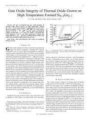
Fig. 5. Simulated and measured responses for an SIR filter. f =1:5 GHz,<br />
N =3, R =0:4, 1=10%, and passband ripple = 0.1 dB. Simulated result<br />
for a UIR filter with identical specification is also plotted for comparison.<br />
Fig. 5 shows simulated results for a third-order Chebyshev<br />
filter with a 0.1-dB ripple level. The filter has GHz,<br />
%, and . The simulation response of a<br />
UIR filter with identical passband specification is also plotted<br />
for comparison. The SIR filter has the first spurious passband<br />
at , as predicted in Fig. 3, which is much higher than the<br />
second spurious response of the UIR filter. Furthermore, this<br />
spurious response shows a bandwidth much smaller than the<br />
second spurious response of the UIR filter. In Fig. 5, a zoomed<br />
area is used to show in detail the fundamental passband performance<br />
of the designed <strong>bandpass</strong> filter. At the center of the passband,<br />
the insertion loss of the UIR filter is 0.1 dB better than that<br />
of the SIR filter. The experiment and simulation results have a<br />
good agreement.<br />
The filter shown in Fig. 5 is redesigned with % and<br />
, and the results are shown in Fig. 6(a). Again, the<br />
response for a UIR filter is also plotted for comparison. The first<br />
spurious response for the SIR filter is pushed to , as well<br />
as predicted in Fig. 3. It is interesting to note that the shadow<br />
area in the plot demonstrates the improvement of stopband rejection<br />
by the SIRs. As shown in the zoomed area, at the center<br />
of passband, the insertion loss of the UIR filter is 0.7 dB better<br />
than that of the SIR filter. Fig. 6(b) presents the photograph of<br />
the fabricated circuit.<br />
It is worth mentioning that the attenuation level at frequencies<br />
around of the filter in Fig. 6(a) is better than that of<br />
Fig. 5 by 15–25 dB. In our numerical experiments, it is found
1558 <strong>IEEE</strong> TRANSACTIONS ON MICROWAVE THEORY AND TECHNIQUES, VOL. 51, NO. 5, MAY 2003<br />
(a)<br />
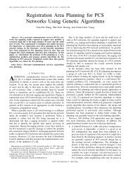
Fig. 7. Simulation responses for an SIR filter with tap-controlled transmission<br />
zeros. For case A, the tap points are determined by R =50. For case B,<br />
one of the two zeros is located at the first spurious resonance (3:76f ). For<br />
case C, both zeros are at the first spurious resonance (3:76f ). f =1:5 GHz,<br />
N =5, R =0:2, 1=10%, and passband ripple = 0.1 dB.<br />
(b)<br />
Fig. 6. (a) Simulated and measured responses for an SIR filter. f =1:5 GHz,<br />
N = 3, R = 0:2, 1 = 6%, and passband ripple = 0.1 dB. Simulated<br />
result for a UIR filter with identical specification is also plotted for comparison.<br />
(b) Photograph of the fabricated circuit.<br />
that the attenuation level in the upper stopband also depends on<br />
the bandwidth of the filter. The choice of the value, however,<br />
seems to dominate the attenuation level of the filter at . This<br />
finding leads us to use an SIR with a small for designing filters<br />
of wide stopband with satisfactory rejection levels in the<br />
upper stopband.<br />
In both Figs. 5 and 6(a), the two transmission zeros on both<br />
sides of the passband are created by tapping the input and output<br />
<strong>resonator</strong>s without any tuning. It means that the tap point is determined<br />
by the value with , and there is no need<br />
using any quarter-wave transformer.<br />
In Fig. 3, the peak value of for is 6.5. To<br />
reach this goal, we can use the two extra zeros, created by tapping<br />
the input and output <strong>resonator</strong>s, to cancel the first spurious<br />
resonance at . The effectiveness of suppressing the spurious<br />
resonance using only one zero is, of course, different from<br />
that using two. This is investigated in Fig. 7 with a fifth-order<br />
<strong>bandpass</strong> filter, whose % and GHz. It is to be<br />
noted that should be used to have .<br />
There are three plots shown in Fig. 7. For simulation , the<br />
tap points are determined by<br />
, and no <strong>impedance</strong><br />
transformer is required. For simulation , one of the two zeros<br />
is located at the first spurious resonance ( or 5.6 GHz);<br />
and for simulation , both zeros are located at the first spurious<br />
resonance. Case has a peak spurious value of higher<br />
than 5dBat , while cases and have approximately<br />
30 and 45 dB, respectively. It is interesting to note that the<br />
for plot at is below 40 dB. The reason is that<br />
is a higher order zero created by tapping at one of the end res-<br />
Fig. 8. Simulation and measurement responses for case C of Fig. 7.<br />
onators. This issue is outside of the scope of this paper, and will<br />
be discussed in another form.<br />
Fig. 8 compares the simulation and measured responses for<br />
case of Fig. 7. It can be observed that both responses have a<br />
good agreement. Their worst rejection levels in the entire upper<br />
stopband are 45 dB before the spurious response goes up.<br />
From the results shown in Fig. 7, it is possible to exploit the<br />
two transmission zeros to cancel the two leading spurious resonances<br />
in the upper stopband with a tradeoff of the attenuation<br />
level. If this is done for the case of , the stopband<br />
can be further extended to , the third spurious harmonic,<br />
as predicted in Fig. 3. To this end, we have to choose<br />
and move the tapping to the positions that creates transmission<br />
zeros whose frequencies equal the first and second spurious<br />
resonances of the SIR at and , respectively.<br />
Fig. 9(a) plots the simulated and measured responses of the<br />
<strong>bandpass</strong> filter. A minimal rejection level of 30 dB is obtained<br />
in the stopband before the third spurious response at rises.<br />
Fig. 9(b) shows the photograph of the filter.<br />
It is to be noted that, in our experience of measuring the responses<br />
of filters of Figs. 6, 8 and 9, the results in the stopband<br />
can be quite sensitive to the flatness of the circuit board. Since<br />
the RT/Duroid 5880 substrate is a soft board, a metallic carrier<br />
is suggested to support the circuit during the measurement.
KUO AND SHIH: MICROSTRIP SIR BANDPASS FILTER 1559<br />
(b)<br />
Fig. 9. (a) Simulation and measured responses of the fabricated filter.<br />
(b) Photograph of the circuit. The passband specification of the filter is<br />
identical to that of Fig. 8.<br />
(a)<br />
VII. CONCLUSION<br />
Given a characteristic <strong>impedance</strong> ratio of the high- and<br />
low- segments, an SIR is shown to have a maximally wide<br />
stopband for certain length ratios of the segments. Filters<br />
with SIRs of lower <strong>impedance</strong> ratios are found to have higher<br />
spurious resonant frequencies and better rejection levels at ,<br />
twice the passband frequency. The singly loaded for a<br />
tapped SIR is derived. It is shown that proper tappings at both<br />
the input and output <strong>resonator</strong>s can create two independent<br />
tunable transmission zeros in the stopband, which can be<br />
used to improve the attenuation and selectivity of the filters.<br />
Bandpass filters with stopbands up to , , and<br />
are designed and fabricated. A very good agreement between<br />
the simulation and measurement is obtained.<br />
[5] M. Makimoto and S. Yamashita, “Bandpass filters using parallel-coupled<br />
stripline <strong>stepped</strong> <strong>impedance</strong> <strong>resonator</strong>s,” <strong>IEEE</strong> Trans. Microwave<br />
Theory Tech., vol. MTT-28, pp. 1413–1417, Dec. 1980.<br />
[6] S.-Y. Lee and C.-M. Tsai, “New cross-coupled filter design using improved<br />
hairpin <strong>resonator</strong>,” <strong>IEEE</strong> Trans. Microwave Theory Tech., vol.<br />
48, pp. 2482–2490, Dec. 2000.<br />
[7] L. Zhu and K. Wu, “Accurate circuit model of interdigital capacitor and<br />
its application to design of new quasi-lumped miniaturized filters with<br />
suppression of harmonic resonance,” <strong>IEEE</strong> Trans. Microwave Theory<br />
Tech., vol. 48, pp. 347–356, Mar. 2000.<br />
[8] S. Denis, C. Person, S. Toutain, S. Vigneron, and B. Theron, “Improvement<br />
of global performances of band-pass filters using nonconventional<br />
<strong>stepped</strong> <strong>impedance</strong> <strong>resonator</strong>s,” in 28th Eur. Microwave Conf. Dig.,<br />
1998, pp. 323–328.<br />
[9] M. Makimoto and S. Yamashita, Microwave Resonators and Filters<br />
for Wireless Communication—Theory and Design. Berlin, Germany:<br />
Springer, 2001, pp. 79–83.<br />
[10] C. Quendo, E. Rius, C. Person, and M. Ney, “Integration of optimized<br />
low-pass filters in a <strong>bandpass</strong> filter for out-of-band improvement,” <strong>IEEE</strong><br />
Trans. Microwave Theory Tech., vol. 49, pp. 2376–2383, Dec. 2001.<br />
[11] J. S. Wong, “<strong>Microstrip</strong> tapped-line filter design,” <strong>IEEE</strong> Trans. Microwave<br />
Theory Tech., vol. MTT-27, pp. 44–50, Jan. 1979.<br />
[12] M. Matsuo, H. Yabuki, and M. Makimoto, “The design of a half-wavelength<br />
<strong>resonator</strong> BPF with attenuation poles at desired frequencies,” in<br />
<strong>IEEE</strong> MTT-S Int. Microwave Symp. Dig., 2000, pp. 1181–1184.<br />
[13] K. Wada and I. Awai, “Heuristic models of half-wavelength <strong>resonator</strong><br />
<strong>bandpass</strong> filter with attenuation poles,” Electron. Lett., vol. 35, no. 5,<br />
pp. 401–402, Mar. 1999.<br />
[14] K. Wada and O. Hashimoto, “Fundamentals of open-ended <strong>resonator</strong>s<br />
and their application to microwave filters,” IEICE Trans. Electron., vol.<br />
E83-C, no. 11, pp. 1763–1775, Nov. 2000.<br />
[15] J.-T. Kuo and E. Shih, “Stepped <strong>impedance</strong> <strong>resonator</strong> <strong>bandpass</strong> filters<br />
with tunable transmission zeros and its application to wide stopband design,”<br />
in <strong>IEEE</strong> MTT-S Int. Microwave Symp. Dig., 2002, pp. 1613–1616.<br />
[16] G. L. Matthaei, L. Young, and E. M. T. Jones, Microwave Filters,<br />
Impedance-Matching Network, and Coupling Structures. Norwood,<br />
MA: Artech House, 1980.<br />
Jen-Tsai Kuo (S’88–M’92) received the Ph.D. degree<br />
from the Institute of Electronics, National Chiao<br />
Tung University (NCTU), Hsinchu, Taiwan, R.O.C.,<br />
in 1992.<br />
Since 1984, he has been with the Department<br />
of Communication Engineering, NCTU, as a<br />
Lecturer in both the Microwave and Communication<br />
Electronics Laboratories. He became a Professor in<br />
2000. From 1995 to 1996, he was a Visiting Scholar<br />
with the University of California at Los Angeles. His<br />
research interests include the analysis and design of<br />
microwave circuits, high-speed interconnects and packages, field-theoretical<br />
studies of guided waves, and numerical techniques in electromagnetics.<br />
REFERENCES<br />
[1] D. M. Pozar, Microwave Engineering, 2nd ed. New York: Wiley, 1998,<br />
ch. 8.<br />
[2] C.-Y. Chang and T. Itoh, “A modified parallel-coupled filter structure<br />
that improves the upper stopband rejection and response symmetry,”<br />
<strong>IEEE</strong> Trans. Microwave Theory Tech, vol. 39, pp. 310–314, Feb. 1991.<br />
[3] A. Riddle, “High performance parallel-coupled microstrip filters,” in<br />
<strong>IEEE</strong> MTT-S Int. Microwave Symp. Dig., 1988, pp. 427–430.<br />
[4] I. J. Bahl, “Capacitively compensated high performance parallel-coupled<br />
microstrip filters,” in <strong>IEEE</strong> MTT-S Int. Microwave Symp. Dig.,<br />
1989, pp. 679–682.<br />
Eric Shih was born in Taoyuan, Taiwan, R.O.C., on<br />
April 12, 1976. He received the B.S. degree in engineering<br />
and system science from the National Tsing<br />
Hua University (NTHU), Hsinchu, Taiwan, R.O.C.,<br />
in 1998, and is currently working toward the Ph.D.<br />
degree in communication engineering at the National<br />
Chiao Tung University (NCTU), Hsinchu, Taiwan,<br />
R.O.C.<br />
His research interests include the design of<br />
microwave planar filters and associated RF modules<br />
for microwave and millimeter-wave applications.