Parallel-coupled microstrip filters with over-coupled ... - IEEE Xplore
Parallel-coupled microstrip filters with over-coupled ... - IEEE Xplore
Parallel-coupled microstrip filters with over-coupled ... - IEEE Xplore

You also want an ePaper? Increase the reach of your titles
YUMPU automatically turns print PDFs into web optimized ePapers that Google loves.
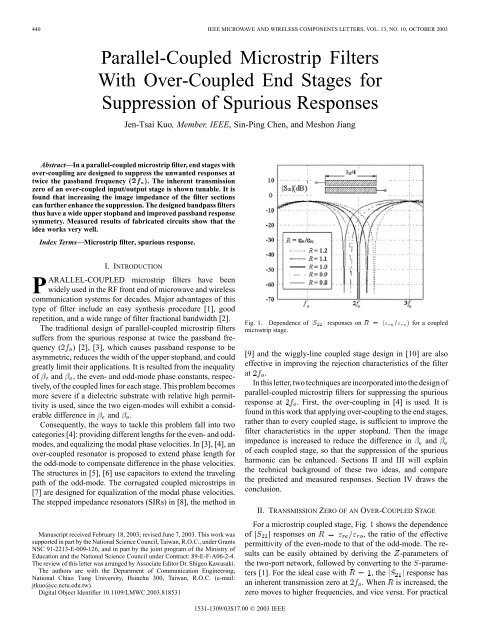
440 <strong>IEEE</strong> MICROWAVE AND WIRELESS COMPONENTS LETTERS, VOL. 13, NO. 10, OCTOBER 2003<strong>Parallel</strong>-Coupled Microstrip FiltersWith Over-Coupled End Stages forSuppression of Spurious ResponsesJen-Tsai Kuo, Member, <strong>IEEE</strong>, Sin-Ping Chen, and Meshon JiangAbstract—In a parallel-<strong>coupled</strong> <strong>microstrip</strong> filter, end stages <strong>with</strong><strong>over</strong>-coupling are designed to suppress the unwanted responses attwice the passband frequency (2 ). The inherent transmissionzero of an <strong>over</strong>-<strong>coupled</strong> input/output stage is shown tunable. It isfound that increasing the image impedance of the filter sectionscan further enhance the suppression. The designed bandpass <strong>filters</strong>thus have a wide upper stopband and improved passband responsesymmetry. Measured results of fabricated circuits show that theidea works very well.Index Terms—Microstrip filter, spurious response.I. INTRODUCTIONPARALLEL-COUPLED <strong>microstrip</strong> <strong>filters</strong> have beenwidely used in the RF front end of microwave and wirelesscommunication systems for decades. Major advantages of thistype of filter include an easy synthesis procedure [1], goodrepetition, and a wide range of filter fractional bandwidth [2].The traditional design of parallel-<strong>coupled</strong> <strong>microstrip</strong> <strong>filters</strong>suffers from the spurious response at twice the passband frequency( ) [2], [3], which causes passband response to beasymmetric, reduces the width of the upper stopband, and couldgreatly limit their applications. It is resulted from the inequalityof and , the even- and odd-mode phase constants, respectively,of the <strong>coupled</strong> lines for each stage. This problem becomesmore severe if a dielectric substrate <strong>with</strong> relative high permittivityis used, since the two eigen-modes will exhibit a considerabledifference in and .Consequently, the ways to tackle this problem fall into twocategories [4]: providing different lengths for the even- and oddmodes,and equalizing the modal phase velocities. In [3], [4], an<strong>over</strong>-<strong>coupled</strong> resonator is proposed to extend phase length forthe odd-mode to compensate difference in the phase velocities.The structures in [5], [6] use capacitors to extend the travelingpath of the odd-mode. The corrugated <strong>coupled</strong> <strong>microstrip</strong>s in[7] are designed for equalization of the modal phase velocities.The stepped impedance resonators (SIRs) in [8], the method inManuscript received February 18, 2003; revised June 7, 2003. This work wassupported in part by the National Science Council, Taiwan, R.O.C., under GrantsNSC 91-2213-E-009-126, and in part by the joint program of the Ministry ofEducation and the National Science Council under Contract: 89-E-F-A06-2-4.The review of this letter was arranged by Associate Editor Dr. Shigeo Kawasaki.The authors are <strong>with</strong> the Department of Communication Engineering,National Chiao Tung University, Hsinchu 300, Taiwan, R.O.C. (e-mail:jtkuo@cc.nctu.edu.tw).Digital Object Identifier 10.1109/LMWC.2003.818531Fig. 1. Dependence of jS j responses on R =(" =" ) for a <strong>coupled</strong><strong>microstrip</strong> stage.[9] and the wiggly-line <strong>coupled</strong> stage design in [10] are alsoeffective in improving the rejection characteristics of the filterat .In this letter, two techniques are incorporated into the design ofparallel-<strong>coupled</strong> <strong>microstrip</strong> <strong>filters</strong> for suppressing the spuriousresponse at . First, the <strong>over</strong>-coupling in [4] is used. It isfound in this work that applying <strong>over</strong>-coupling to the end stages,rather than to every <strong>coupled</strong> stage, is sufficient to improve thefilter characteristics in the upper stopband. Then the imageimpedance is increased to reduce the difference in andof each <strong>coupled</strong> stage, so that the suppression of the spuriousharmonic can be enhanced. Sections II and III will explainthe technical background of these two ideas, and comparethe predicted and measured responses. Section IV draws theconclusion.II. TRANSMISSION ZERO OF AN OVER-COUPLED STAGEFor a <strong>microstrip</strong> <strong>coupled</strong> stage, Fig. 1 shows the dependenceof responses on , the ratio of the effectivepermittivity of the even-mode to that of the odd-mode. The resultscan be easily obtained by deriving the -parameters ofthe two-port network, followed by converting to the -parameters[1]. For the ideal case <strong>with</strong> , the response hasan inherent transmission zero at . When is increased, thezero moves to higher frequencies, and vice versa. For practical1531-1309/03$17.00 © 2003 <strong>IEEE</strong>
KUO et al.: PARALLEL-COUPLED MICROSTRIP FILTERS WITH OVER-COUPLED END STAGES 441Fig. 2.stages.Layout for a third-order filter. Over-couplings are applied to the end<strong>coupled</strong> <strong>microstrip</strong>s, is greater than unity. The passband responsesin the neighborhood of , however, do not change significantlywhen the value of is changed, since the derivativeof the coupling response is zero at . Therefore when a stageis <strong>over</strong>-<strong>coupled</strong>, i.e. the coupling length is longer than ,the passband response will be almost unchanged, and the inherentzero will move to a frequency lower than . In otherwords, the effectiveness of increasing the coupling length of a<strong>coupled</strong>-line stage on the zero is equivalent to that of decreasing, which is also equivalent to increasing or decreasing .It implies that from the circuit design point of view, the inherentzero can be tunable, <strong>with</strong>in a certain range, by merely adjustingthe length for the <strong>over</strong>-coupling. Since the position of the zerois close to the band of the spurious responses, it can be used toenhance the filter performance around .Fig. 2 shows the layout of a third-order Chebyshev bandpassfilter, of which both the end stages are <strong>over</strong>-<strong>coupled</strong>. Fig. 3 plotsthe simulation and measured results for a third- and a fifth-order<strong>filters</strong>. The detailed passband responses are also plotted in thezoomed windows. The <strong>filters</strong> are designed by the classical synthesismethod [1], followed <strong>with</strong> adding an extra section to theend stages for <strong>over</strong>-coupling. The lengths of the extra sectionsare chosen so that the peak of the spurious response is minimized.The IE3D [11] is used for the electromagnetic simulations.The simulation results for <strong>filters</strong> directly synthesized bythe traditional method, i.e. <strong>with</strong>out any <strong>over</strong>-coupling, are alsoplotted for comparison. The measured peak rejection levels forthe <strong>filters</strong> <strong>with</strong> proper <strong>over</strong>-couplings are no more than 30 dB.It can be seen that a suppression of at least 20 dB to the spuriousresponses is obtained by using the <strong>over</strong>-<strong>coupled</strong> stages.It is noted that the design in Fig. 2 is much simpler than that in[4], where <strong>over</strong>-coupling is applied to every <strong>coupled</strong> stage. Thetuning in our design involves only two <strong>over</strong>-couplings at the endstages, while that in [4] involves the coupling coefficients of allthe <strong>coupled</strong> stages, which include three-line sections or anglednonuniform <strong>coupled</strong> lines. The substrates in both works have asimilar dielectric constant, but the thickness of our substrate ismore than three times that of the counterpart. Nevertheless, themeasured suppression to the spurious passband in Fig. 3(a) andFig. 3(b) shows a similar level to that of the optimized filter in[4].Fig. 3. Simulated and measured responses for Chebyshev bandpass <strong>filters</strong>. Thecenter frequency f =2GHzand passband ripple =0:1dB. The substrate has" =10:2 and thickness h =1:27 mm. (a) Responses of a third-order filter<strong>with</strong> fractional bandwidth 1 = 20%. The electrical lengths for <strong>over</strong>-couplingat the end stages are =12:7 and =17:2 . (b) Responses of a fifth-orderfilter <strong>with</strong> 1=15%, =15:1 and =18:8 .III. ENHANCING THE SUPPRESSION BYINCREASING THE IMAGE IMPEDANCESuppressing spurious harmonics for parallel-<strong>coupled</strong> <strong>microstrip</strong><strong>filters</strong> on a substrate <strong>with</strong> larger is more difficult thanthose on a substrate <strong>with</strong> smaller , since the eigen-modes willexhibit more deviation in phase velocities, which is the veryFig. 4. Comparison of " and " for two pairs of <strong>coupled</strong> lines. Z =50:W = 0:590 mm, S = 0:220 mm; Z = 80 : W = 0:206 mm, S =0:396 mm.
442 <strong>IEEE</strong> MICROWAVE AND WIRELESS COMPONENTS LETTERS, VOL. 13, NO. 10, OCTOBER 2003pairs of <strong>coupled</strong> <strong>microstrip</strong>s, of which the dimensions are thosefor the first stages of the <strong>filters</strong> shown in Fig. 3(a) and Fig. 5(a).The relative deviation between and for the 50 case isreduced from 21.9% to 10.6% for the 80 case. The responsesfor two <strong>filters</strong> <strong>with</strong>are shown in Fig. 5(a) andFig. 5(b), of which the specifications are identical to those ofFig. 3(a) and Fig. 3(b), respectively. The <strong>over</strong>-coupling is alsoincluded in the circuit design. As indicated for both <strong>filters</strong>, themeasured attenuation levels at are better than 50 dB. Forthe particular case studies shown, the suppression is enhancedby 15 dB by increasing the image impedance of the filter. Itis to be noted that the passband responses are close to beingunchanged.IV. CONCLUSIONThis letter shows an effective example of common parallel-<strong>coupled</strong><strong>microstrip</strong> filter design. Suppression of thespurious response is achieved by introducing <strong>over</strong>-coupling tothe end stages and increasing the image impedance of the filter.The <strong>over</strong>-coupling is applied to the end stages only. A <strong>coupled</strong><strong>microstrip</strong> stage <strong>with</strong> higher image impedance is shown tohave smaller difference in and , and parallel-<strong>coupled</strong><strong>microstrip</strong> <strong>filters</strong> <strong>with</strong> higher image impedances also show animproved rejection at .Fig. 5. Simulated and measured responses for <strong>filters</strong> <strong>with</strong> image impedanceZ =80. The design specifications of the filter and the substrate are identicalto those in Fig. 3. (a) Responses of a third-order filter <strong>with</strong> 1 = 20%, =12:5 and =12:9 . (b) Responses of a fifth-order filter <strong>with</strong> 1 = 15%, =14:1 and =15:6 .reason that the spurious response arises. Thus, any techniquefor reducing the deviation between the modal phase velocitieswill be helpful in the suppression of unwanted harmonics. Itis found that if the image impedance of a <strong>coupled</strong> stage canbe increased, the difference between and of the <strong>coupled</strong>lines can be reduced at the same time. For keeping both systemreference impedance and the passband response unaltered atthe same time, the method in [12] can be invoked to designparallel-<strong>coupled</strong> <strong>filters</strong> <strong>with</strong> an image impedance other than50 . In this letter, the image impedance of the filter ischanged from 50 to 80 . Fig. 4 compares and of twoREFERENCES[1] D. M. Pozar, Microwave Engineering, 2nd ed. New York: Wiley, 1998.[2] C.-Y. Chang and T. Itoh, “A modified parallel-<strong>coupled</strong> filter structurethat improves the upper stopband rejection and response symmetry,”<strong>IEEE</strong> Trans. Microwave Theory Tech., vol. 39, pp. 310–314, Feb. 1991.[3] B. Easter and K. A. Merza, “<strong>Parallel</strong>-<strong>coupled</strong>-line <strong>filters</strong> for inverted-<strong>microstrip</strong>and suspended-substrate MIC’s,” in 11th Eur. Microwave Conf.Dig., 1981, pp. 164–167.[4] A. Riddle, “High performance parallel <strong>coupled</strong> <strong>microstrip</strong> <strong>filters</strong>,” in<strong>IEEE</strong> MTT-S Symp. Dig., 1988, pp. 427–430.[5] S. L. March, “Phase velocity compensation in parallel-<strong>coupled</strong> <strong>microstrip</strong>,”in <strong>IEEE</strong> MTT-S Symp. Dig., 1982, pp. 410–412.[6] I. J. Bahl, “Capacitively compensated high performance parallel <strong>coupled</strong><strong>microstrip</strong> <strong>filters</strong>,” in <strong>IEEE</strong> MTT-S Symp. Digest, 1989, pp. 679–682.[7] J.-T. Kuo, W.-H. Hsu, and W.-T. Huang, “<strong>Parallel</strong> <strong>coupled</strong> <strong>microstrip</strong> <strong>filters</strong><strong>with</strong> suppression of harmonic response,” <strong>IEEE</strong> Microwave WirelessComp. Lett., vol. 12, pp. 383–385, Oct. 2002.[8] M. Makimoto and S. Yamashita, Microwave Resonators and Filtersfor Wireless Communication—Theory and Design. Berlin, Germany:Springer, 2001, pp. 79–83.[9] C. Wang and K. Chang, “Microstrip multiplexer <strong>with</strong> four channels forbroadband system applications,” Int. J. RF Microwave CAE 11, pp.48–54, Nov. 2001.[10] T. Lopetegi, M. A. G. Laso, J. Hernández, M. Bacaicoa, D. Benito, M.J. Garde, M. Sorolla, and M. Guglielmi, “New <strong>microstrip</strong> ‘wiggly-line’<strong>filters</strong> <strong>with</strong> spurious passband suppression,” <strong>IEEE</strong> Trans. MicrowaveTheory Tech., vol. 49, pp. 1593–1598, Sept. 2001.[11] Zeland Software, Inc., IE3D Simulator, Jan. 1997.[12] D. Ahn, C.-S. Kim, M.-H. Chung, D.-H. Lee, D.-W. Lew, and H.-J.Hong, “The design of parallel <strong>coupled</strong> line filter <strong>with</strong> arbitrary imageimpedance,” in <strong>IEEE</strong> MTT-S Symp. Dig., 1998, pp. 909–912.