Design of Microstrip Bandpass Filters With a Dual ... - IEEE Xplore
Design of Microstrip Bandpass Filters With a Dual ... - IEEE Xplore
Design of Microstrip Bandpass Filters With a Dual ... - IEEE Xplore
- No tags were found...

Create successful ePaper yourself
Turn your PDF publications into a flip-book with our unique Google optimized e-Paper software.
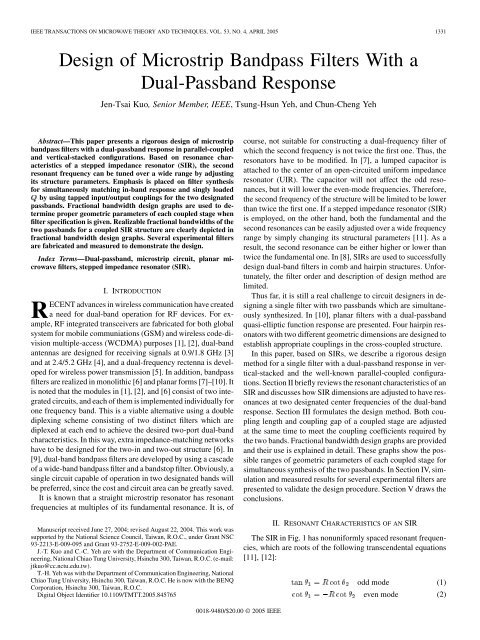
<strong>IEEE</strong> TRANSACTIONS ON MICROWAVE THEORY AND TECHNIQUES, VOL. 53, NO. 4, APRIL 2005 1331<strong>Design</strong> <strong>of</strong> <strong>Microstrip</strong> <strong>Bandpass</strong> <strong>Filters</strong> <strong>With</strong> a<strong>Dual</strong>-Passband ResponseJen-Tsai Kuo, Senior Member, <strong>IEEE</strong>, Tsung-Hsun Yeh, and Chun-Cheng YehAbstract—This paper presents a rigorous design <strong>of</strong> microstripbandpass filters with a dual-passband response in parallel-coupledand vertical-stacked configurations. Based on resonance characteristics<strong>of</strong> a stepped impedance resonator (SIR), the secondresonant frequency can be tuned over a wide range by adjustingits structure parameters. Emphasis is placed on filter synthesisfor simultaneously matching in-band response and singly loadedby using tapped input/output couplings for the two designatedpassbands. Fractional bandwidth design graphs are used to determineproper geometric parameters <strong>of</strong> each coupled stage whenfilter specification is given. Realizable fractional bandwidths <strong>of</strong> thetwo passbands for a coupled SIR structure are clearly depicted infractional bandwidth design graphs. Several experimental filtersare fabricated and measured to demonstrate the design.Index Terms—<strong>Dual</strong>-passband, microstrip circuit, planar microwavefilters, stepped impedance resonator (SIR).I. INTRODUCTIONRECENT advances in wireless communication have createda need for dual-band operation for RF devices. For example,RF integrated transceivers are fabricated for both globalsystem for mobile communiations (GSM) and wireless code-divisionmultiple-access (WCDMA) purposes [1], [2], dual-bandantennas are designed for receiving signals at 0.9/1.8 GHz [3]and at 2.4/5.2 GHz [4], and a dual-frequency rectenna is developedfor wireless power transmission [5]. In addition, bandpassfilters are realized in monolithic [6] and planar forms [7]–[10]. Itis noted that the modules in [1], [2], and [6] consist <strong>of</strong> two integratedcircuits, and each <strong>of</strong> them is implemented individually forone frequency band. This is a viable alternative using a doublediplexing scheme consisting <strong>of</strong> two distinct filters which arediplexed at each end to achieve the desired two-port dual-bandcharacteristics. In this way, extra impedance-matching networkshave to be designed for the two-in and two-out structure [6]. In[9], dual-band bandpass filters are developed by using a cascade<strong>of</strong> a wide-band bandpass filter and a bandstop filter. Obviously, asingle circuit capable <strong>of</strong> operation in two designated bands willbe preferred, since the cost and circuit area can be greatly saved.It is known that a straight microstrip resonator has resonantfrequencies at multiples <strong>of</strong> its fundamental resonance. It is, <strong>of</strong>Manuscript received June 27, 2004; revised August 22, 2004. This work wassupported by the National Science Council, Taiwan, R.O.C., under Grant NSC93-2213-E-009-095 and Grant 93-2752-E-009-002-PAE.J.-T. Kuo and C.-C. Yeh are with the Department <strong>of</strong> Communication Engineering,National Chiao Tung University, Hsinchu 300, Taiwan, R.O.C. (e-mail:jtkuo@cc.nctu.edu.tw).T.-H. Yeh was with the Department <strong>of</strong> Communication Engineering, NationalChiao Tung University, Hsinchu 300, Taiwan, R.O.C. He is now with the BENQCorporation, Hsinchu 300, Taiwan, R.O.C.Digital Object Identifier 10.1109/TMTT.2005.845765course, not suitable for constructing a dual-frequency filter <strong>of</strong>which the second frequency is not twice the first one. Thus, theresonators have to be modified. In [7], a lumped capacitor isattached to the center <strong>of</strong> an open-circuited uniform impedanceresonator (UIR). The capacitor will not affect the odd resonances,but it will lower the even-mode frequencies. Therefore,the second frequency <strong>of</strong> the structure will be limited to be lowerthan twice the first one. If a stepped impedance resonator (SIR)is employed, on the other hand, both the fundamental and thesecond resonances can be easily adjusted over a wide frequencyrange by simply changing its structural parameters [11]. As aresult, the second resonance can be either higher or lower thantwice the fundamental one. In [8], SIRs are used to successfullydesign dual-band filters in comb and hairpin structures. Unfortunately,the filter order and description <strong>of</strong> design method arelimited.Thus far, it is still a real challenge to circuit designers in designinga single filter with two passbands which are simultaneouslysynthesized. In [10], planar filters with a dual-passbandquasi-elliptic function response are presented. Four hairpin resonatorswith two different geometric dimensions are designed toestablish appropriate couplings in the cross-coupled structure.In this paper, based on SIRs, we describe a rigorous designmethod for a single filter with a dual-passband response in vertical-stackedand the well-known parallel-coupled configurations.Section II briefly reviews the resonant characteristics <strong>of</strong> anSIR and discusses how SIR dimensions are adjusted to have resonancesat two designated center frequencies <strong>of</strong> the dual-bandresponse. Section III formulates the design method. Both couplinglength and coupling gap <strong>of</strong> a coupled stage are adjustedat the same time to meet the coupling coefficients required bythe two bands. Fractional bandwidth design graphs are providedand their use is explained in detail. These graphs show the possibleranges <strong>of</strong> geometric parameters <strong>of</strong> each coupled stage forsimultaneous synthesis <strong>of</strong> the two passbands. In Section IV, simulationand measured results for several experimental filters arepresented to validate the design procedure. Section V draws theconclusions.II. RESONANT CHARACTERISTICS OF AN SIRThe SIR in Fig. 1 has nonuniformly spaced resonant frequencies,which are roots <strong>of</strong> the following transcendental equations[11], [12]:odd mode (1)even mode (2)0018-9480/$20.00 © 2005 <strong>IEEE</strong>
1332 <strong>IEEE</strong> TRANSACTIONS ON MICROWAVE THEORY AND TECHNIQUES, VOL. 53, NO. 4, APRIL 2005Fig. 1.SIR with input/output tapping.Fig. 2. Normalized f =f and f =f for an SIR with impedance ratios R =0:4; 0:67; 1:5, and 2:5. u = =( + ).where and are electrical lengths <strong>of</strong> the microstrip sectionswith characteristic impedances and , respectively,andis the impedance ratio <strong>of</strong> the SIR. These twoequations can be formulated by setting the plane <strong>of</strong> symmetryP–P’ to be short- and open-circuited for the odd and even resonances,respectively. The fundamental and consecutive higherorder resonances <strong>of</strong> the SIR occur alternatively in odd and evenmodes.Based on the solutions to (1) and (2), Fig. 2 shows the secondand third resonant frequencies normalized with respectto the first one for , and . Thevariable <strong>of</strong> the horizontal axis , called the length ratio, is definedasThe plots in Fig. 2 provide proper and values to realize thedesignated ratio. Fig. 2 clearly shows that, the smalleris, the larger the maximum ratio <strong>of</strong> is. If isrequired, should be chosen, and vice versa. Also, awayfrom the plateau or valley <strong>of</strong> any <strong>of</strong> the curves, one can see thatthere are always two possible values for a given to obtain thesame ratio. The value corresponding to the largeris preferred, since it corresponds a wider upper rejection band.For example, if the two passbands are at 2.45 and 5.8 GHz, i.e.,, and is used, then at pointis better than that at , since the ratio at ’ is larger thanthat at ’.III. FRACTIONAL BANDWIDTH DESIGN GRAPHNext, we determine the coupling scheme <strong>of</strong> each pair <strong>of</strong> adjacentSIRs to meet the required coupling coefficients for tworespective bands. When two resonators have a close proximity,(3)Fig. 3. (a) Coupling structure. (b) Fractional bandwidth design graph. f =2:45 GHz, f = 5:2 GHz. Dimensions <strong>of</strong> SIR in mm: W = 0:89;W =1:30;` =11:38;` =9:32. Substrate: " =2:2; thickness = 0:508 mm.and their resonant frequencies are re-the coupling coefficientlated by [11]where and are peak frequencies in the transmission responseobtained by using excitation through a gap to the outerends <strong>of</strong> the coupled resonators. There are resonators in anth-order filter. In our filter design, the coupling coefficientsbetween the th and th resonators have also to be specifiedby element values and <strong>of</strong> the low-pass filterprototype and fractional bandwidth as [13]where is the cut<strong>of</strong>f frequency <strong>of</strong> the low-pass filter prototype,and the subscript or denotes the first or the second passband.Note that (4) should be evaluated around two designatedcenter frequencies to meet the use <strong>of</strong> (5).A. Parallel-Coupled <strong>Filters</strong> <strong>With</strong> Tapped Input/OutputTaking the advantage <strong>of</strong> structural symmetry, we designChebyshev filters only <strong>of</strong> odd orders for this configuration. Forexample, a fifth-order Chebyshev filter with tapped input/outputhas and . For a coupledstage in Fig. 3(a), let the coupling length be and the couplinggap be . In conventional design <strong>of</strong> a bandpass filter with asingle passband, the coupling length is usually half <strong>of</strong> that<strong>of</strong> an entire resonator, e.g., [11]. In fact, both and can betuned in certain respective ranges to provide the same couplingcoefficient. In other words, there are two degrees <strong>of</strong> freedom in(4)(5)
KUO et al.: DESIGN OF MICROSTRIP BANDPASS FILTERS WITH DUAL-PASSBAND RESPONSE 1333designing a coupled stage. Thus, it is possible to make a coupledstage match the two coefficients required by specifications<strong>of</strong> two passbands.The coupling length and gap <strong>of</strong> a coupled stage in Fig. 3(a)have to provide two proper coupling coefficients at two designatedfrequencies. This can be done by constructing a fractionalbandwidth design graph shown in Fig. 3(b) as follows. Let thedesign frequencies be at 2.45 and 5.2 GHz and both passbandshave 0.1-dB ripple levels. Given mm , and, and mm , the coupling coefficients<strong>of</strong> the coupled SIRs are evaluated by (4) using the EM simulationpackage IE3D. 1 Note that the coupling coefficient in (5)is proportional to the fractional bandwidth, since the elementvalues <strong>of</strong> the low-pass filter prototype are constants when filterorder and ripple level are specified. Thus, the coordinates <strong>of</strong>fractional bandwidth design graphs for this coupling structureassociated with filter specification are then obtained. It is worthmentioning that the right vertical axis can be obtained from theleft one by just multiplying a constant ,and the upper axis can be scaled from the lower one in a similarfashion.The use <strong>of</strong> Fig. 3(b) can be explained as follows. First, notethat, for all possible and values given in Fig. 3(b), possibleis between 0.04 and 0.17, and possible is less than0.075. If and are chosen, one can locatea point with mm and mm forand , and locate a point with mmand mm for and . It is beneficial toknow the feasible bandwidths for the filter specification beforethe circuit is designed. This can be done by drawing a straightline <strong>of</strong>constant with the graph. For example, when, the dashed line clearly indicates that there isno solution within the given ranges <strong>of</strong> and for designing adual-passband response. However, when, i.e., both passbands have identical absolute bandwidths,realizable is from 0.075 (upper axis) to 0.145 (lower axis)and is from 0.035 (right axis) to 0.068 (left axis), as indicated.It is noted that, when the SIR geometries or the designfrequencies are changed, the design graphs should be recalculated.Fig. 3(b) is also useful for design <strong>of</strong> a third-order Chebyshevfilter. Again, we have. The horizontal axis<strong>of</strong> the design graphs is that <strong>of</strong> Fig. 3(b) scaled by multiplying, and the verticalaxis can be obtained in the same way.B. Vertical-Stacked <strong>Filters</strong>We are also interested in designing vertical-stacked SIR filterswith a dual-passband response. One <strong>of</strong> the important features <strong>of</strong>this filter is its compact area [14]. Two basic coupling structuresA and B involved in circuit design are shown in Fig. 4(a). Basedon these two couplings, the filter can be designed in two possibleconfigurations. One starts with coupling A and the other withB. Let’s call the former filter type and the latter type .Ina vertical-stacked filter <strong>of</strong> order , structures A and B occuralternatively. For example, schematic layouts for such fourth-1 IE3D Simulator, Zeland S<strong>of</strong>tware Inc., Freemont, CA, Jan. 1997.Fig. 4. Structures and design graphs for vertical-stacked SIR filters.(a) Coupling structures. (b) Schematic layouts for fourth-order filters <strong>of</strong> typesA and B. (c) Fractional bandwidth design graphs for filter type A. (d) <strong>Design</strong>graphs for filter type B. f = 2:45 GHz and f = 5:8 GHz. Dimensions<strong>of</strong> SIR in mm: W = 0:46;W = 1:11;` = ` = 9:47. Substrate:" =2:2; thickness = 0:508 mm.order filters <strong>of</strong> types and are given in Fig. 4(b). For a filter <strong>of</strong>type , only and need establishing by structuresA and B, respectively.Fig. 4(c) plots the design graphs for filter type . The SIRhas GHz, GHz, ,and. The coordinates are based on a fourth-orderChebyshev response with a ripple level <strong>of</strong> 0.1 dB. For both thehorizontal and vertical axes <strong>of</strong> Fig. 4(c), the correspondingand are enforced identical after <strong>of</strong> coupling structureA and <strong>of</strong> B are multiplied by the square root <strong>of</strong> theproduct <strong>of</strong> element values <strong>of</strong> the low-pass filter prototype.
1334 <strong>IEEE</strong> TRANSACTIONS ON MICROWAVE THEORY AND TECHNIQUES, VOL. 53, NO. 4, APRIL 2005Similarly, the design graphs in Fig. 4(d) are for vertical-stackedfilters <strong>of</strong> type . It is worth mentioning that thedesign graphs in Fig. 4(c) and (d) are originated from the samecoupling coefficients obtained by (4). The two sets <strong>of</strong> graphslook different since the coefficients are multiplied by differentconstants to form the respective horizontal and vertical axes.The significance <strong>of</strong> plotting Fig. 4(d) is tw<strong>of</strong>old. First, theoverlap areas <strong>of</strong> the graphs in Fig. 4(c) and (d) consist <strong>of</strong>possible solutions to filter type and type , respectively.Second, for coupling structure A, the range <strong>of</strong> required gapsizes in Fig. 4(c) is much different from that in Fig. 4(d).C. <strong>Design</strong> <strong>Filters</strong> <strong>of</strong> Higher OrdersThe concept in Fig. 3 can be extended to design parallel-coupledfilters <strong>of</strong> higher orders. If a seventh-order filter is designed,one more horizontal axisand onemore vertical axiscan be added toFig. 3. In this case, the scales <strong>of</strong> all axes in Fig. 3 should bechanged since the element values <strong>of</strong> the seventh-order low-passfilter prototype are different from those <strong>of</strong> a fifth-order one.More axes can be used for synthesizing filters <strong>of</strong> further increasedorders.It is important to note that the realizable and shouldbe the common region <strong>of</strong> all horizontal and vertical axes, respectively.Obviously, the higher the filter order is, the smallerthe realizable regions <strong>of</strong> and will be. In addition, anychange <strong>of</strong> passband specification will cause element values <strong>of</strong>the low-pass filter prototype to vary, and the feasible ranges <strong>of</strong>and will change accordingly.The same idea applies to design <strong>of</strong> higher order filters <strong>of</strong> thevertical-stacked configuration.D. Input/Output TappingTapped-line input is applied to the end resonators. The singlyloaded <strong>of</strong> a tapped resonator is calculated as [15]where is the load impedance seen at the tap point by theresonator looking to the load and is the total susceptance<strong>of</strong> the resonator seen at the tap point. Obviously, in (6) isa function <strong>of</strong> and should be evaluated at the two designatedfrequencies. Letwhere the expression <strong>of</strong> can be derived as in [11]. It isknown that should also be specified by [13]Now, we have to make the tapped point in Fig. 1 satisfyand at both frequencies. Substituting (7) into (8), one canobtain the ratio(6)(7)(8)(9)Fig. 5. Ratio 1 =1 versus the tap position (see Fig. 1). SIR dimensions arein Fig. 3. Total length <strong>of</strong> the SIR is 2` +2` =41:38 mm.Fig. 6. Simulation and measured responses <strong>of</strong> a fifth-order Chebyshev filter.f =2:45 GHz, f =5:2 GHz, 1 =14%; 1 =6%. Dimensions <strong>of</strong> theSIRs are given in Fig. 3.For , Fig. 5 plots against forthe SIR in Fig. 3. It is clear from the plot that, once isspecified, the tap position can be easily located. Again, if the SIRstructure is changed, this plot should be changed accordingly.The load impedances and can be different, and theirratio can be a tunable parameter for the design. For convenience,is used. In this case, the dual-frequency transformer[16] can be employed.IV. SIMULATION AND MEASURED FILTER RESPONSESThree parallel-coupled filters in Figs. 6–8 and two verticalstackedfilters in Figs. 9 and 10 are designed and fabricated todemonstrate the design. Fig. 6 plots the responses <strong>of</strong> a fifth-orderChebyshev filter with fractional bandwidths % and%. The coupling length and gap size for the first andsecond SIRs are mm and mm, andthose for the second and third SIRs aremm andmm, respectively. By letting, the tapposition can be found to be 13.4 mm. Substituting this valueinto (5), one can obtain the load impedances. As shown in Fig. 6, the measured responses have a goodagreement with the simulated results obtained by the IE3D. Inmeasurements, the insertion losses are 1.7 dB and 2.9 dBat the centers <strong>of</strong> the first and second passbands, respectively.Note that the geometric parameters <strong>of</strong> each coupled stage aredetermined based on the design graph in Fig. 3, thus both the
KUO et al.: DESIGN OF MICROSTRIP BANDPASS FILTERS WITH DUAL-PASSBAND RESPONSE 1335Fig. 7. (a) Simulation and measured responses <strong>of</strong> a fifth-order Chebyshevfilter. f =2:45 GHz, f =5:8 GHz, 1 =12%; 1 =7%. Dimensions <strong>of</strong>SIR in mm: W =0:34;W =1:86;` =11:76;` =5:04. (b) Photograph<strong>of</strong> the filter. Substrate " =2:2; thickness = 0:508 mm.Fig. 9. (a) Simulation and measured responses <strong>of</strong> a fourth-order stacked-linefilter <strong>of</strong> type A. f =2:45 GHz, f =5:8 GHz, 1 =7:2%; 1 =6:0%.Dimensions <strong>of</strong> the SIRs are in Fig. 4. Tap position x =12:7 mm. (b) Photograph<strong>of</strong> the filter.Fig. 8. Simulation and measured results for a third-order filter. f =2:45 GHz, f =4:0 GHz, 1 =6:5%; 1 =4:5%. Dimensions <strong>of</strong> the SIRin mm: W =1:55;W =0:43;` = ` =13:85;x =20:01. Substrate" =2:2; thickness = 0:508 mm.simulation and experimental characteristics <strong>of</strong> the entire filtershown in Fig. 6 validate the design procedure in Section III.The levels at the centers <strong>of</strong> the two passbands are betterthan 20 dB, but the maximal magnitudes over the passbandsare about 10 dB. This could be resulted from the fact that thedual-frequency transformer has insufficient bandwidths at theFig. 10. Simulation and measurement results for a fourth-ordervertical-stacked filter <strong>of</strong> type B. f =2:45 GHz, f =5:8 GHz, 1 =7:0%,1 =5:5%. Dimensions <strong>of</strong> the SIRs are given in Fig. 4.two matching frequencies. We try to improve this by makingthe impedance levels at the two frequencies different and redesigningthe impedance-matching network by modifying themethod in [16]. The results show that, if the performance in oneband is improved, then the performance <strong>of</strong> the other deterioratesat the same time. One possible way to resolve this problem couldbe to use a dual-band impedance transformer with three or moresections.
1336 <strong>IEEE</strong> TRANSACTIONS ON MICROWAVE THEORY AND TECHNIQUES, VOL. 53, NO. 4, APRIL 2005Fig. 7(a) plots the responses <strong>of</strong> a fifth-order filter havingGHz, GHz, %, and %. Dimensions<strong>of</strong> the fabricated circuit determined by the design graphare, and the tapposition , all in millimeters. In the measured results, theinsertion losses are 1.8 and 3.0 dB for the first and secondbands, respectively. Fig. 7(b) is a photograph <strong>of</strong> the filter.Fig. 8 plots the results <strong>of</strong> a third-order Chebyshev filter witha passband ripple <strong>of</strong> 0.01 dB. This filter hasGHz,GHz, %, and %. Note thatis less than , so that should be used. The simulatedand measured responses are in good agreement. The measuredinsertion losses are 1.2 and 1.65 dB at the centers <strong>of</strong> the firstand second passbands, respectively.Fig. 9 plots simulation and measured responses <strong>of</strong> a fourthordervertical-stacked filter based on the graphs in Fig. 4(c). It isinteresting to note that it is possible to design a bandpass filterwith a dual-passband response with, i.e., all thefour SIRs are upright stacked. One can find that there is a uniquesolution in Fig. 4(c), where the fractional bandwidths for the firstand second passbands are 7.2% and 6.0%, respectively, and thecorresponding gap sizes are mm and mm.The measured passband insertion losses are 1.8 dB and 2.0dB for the first and the second bands, respectively. Fig. 9(b)shows a photograph <strong>of</strong> the circuit.Fig. 10 plots the responses <strong>of</strong> a fourth-order vertical-stackedfilter <strong>of</strong> type using the design graphs in Fig. 4(c). Ifare chosen, the filter will have 4.5% fractional bandwidths.This is not easy for microstrip implementation. We thenturn to choose % and %. Important geometricparameters are, and, all in millimeters. The measured passband insertionlosses are 2.2 and 2.4 dB for the first and second bands, respectively.V. CONCLUSIONThis paper presents a detailed procedure for design <strong>of</strong> parallel-coupledand vertical-stacked microstrip filters with a dualpassbandresponse. By using SIRs with a fundamental resonanceat GHz, the second frequency can be eitherlarger or smaller than by trimming its dimensions. Thedesign fully utilizes both coupling length and coupling gap <strong>of</strong>a coupled stage to meet the two different coupling coefficientsfor the dual-band purpose. In this study, third- and fifth-orderparallel-coupled filters with , and GHz aredemonstrated. Two fourth-order vertical-stacked filters are alsodesigned and measured. Fractional bandwidth design graphs arekey reference data for the successful design, since they providefeasible fractional bandwidths for the two designated bands. Thedesign procedure also applies to design filters <strong>of</strong> higher orders.The measured responses <strong>of</strong> the fabricated filters not only havesatisfactory responses, but also have good agreement with thesimulation results.ACKNOWLEDGMENTThe authors are grateful to the anonymous reviewers for theirpositive comments, which have enhanced the readability <strong>of</strong> thispaper.REFERENCES[1] S. Wu and B. Razavi, “A 900-MHz/1.8-GHz CMOS receiver for dualbandapplications,” <strong>IEEE</strong> J. Solid-State Circuits, vol. 33, no. 12, pp.2178–2185, Dec. 1998.[2] J. Ryynänen, K. Kivekäs, J. Jussila, A. Pärssinen, and K. A. I. Halonen,“A dual-band RF front-end for WCDMA and GSM applications,” <strong>IEEE</strong>J. Solid-State Circuits, vol. 36, no. 8, pp. 1198–1204, Aug. 2001.[3] D. Llorens, P. Otero, and C. Camacho-Penalosa, “<strong>Dual</strong>-band, singleCPW port, planar-slot antenna,” <strong>IEEE</strong> Trans. Antennas Propagat., vol.51, no. 1, pp. 137–139, Jan. 2003.[4] Y.-L. Kuo and K.-L. Wong, “Printed double-T monopole antenna for2.4/5.2 GHz dual-band WLAN operations,” <strong>IEEE</strong> Trans. Antennas Propagat.,vol. 51, no. 9, pp. 2187–2192, Sep. 2003.[5] Y.-H. Suh and K. Chang, “A high-efficiency dual-frequency rectenna for2.45- and 5.8-GHz wireless power transmission,” <strong>IEEE</strong> Trans. Microw.Theory Tech., vol. 50, no. 7, pp. 1784–1789, Jul. 2002.[6] H. Miyake, S. Kitazawa, T. Ishizaki, T. Yamada, and Y. Nagatomi, “Aminiaturized monolithic dual band filter using ceramic lamination techniquefor dual mode portable telephones,” <strong>IEEE</strong> MTT-S Int. MicrowaveSymp. Dig., pp. 789–792, 1997.[7] K. Wada and O. Hashimoto, “Fundamentals <strong>of</strong> open-ended resonatorsand their application to microwave filters,” IEICE Trans. Electron., vol.E83-C, pp. 1763–1775, Nov. 2000.[8] S.-F. Chang, J.-L. Chen, and S.-C. Chang, “New dual-band bandpassfilters with step-impedance resonators in comb and hairpin structures,”in Asia–Pacific Microwave Conf., 2003, pp. 793–796.[9] L.-C. Tsai and C. W. Hsue, “<strong>Dual</strong>-band bandpass filters using equallengthcoupled-serial-shunted lines and Z-transform technique,” <strong>IEEE</strong>Trans. Microw. Theory Tech., vol. 52, no. 4, pp. 1111–1117, Apr. 2004.[10] J.-T. Kuo and H.-S. Cheng, “<strong>Design</strong> <strong>of</strong> quasi-elliptic function filters witha dual-passband response,” <strong>IEEE</strong> Microw. Compon. Lett., vol. 14, no. 10,pp. 472–474, Oct 2004.[11] J.-T. Kuo and E. Shih, “<strong>Microstrip</strong> stepped impedance resonator bandpassfilter with an extended optimal rejection bandwidth,” <strong>IEEE</strong> Trans.Microw. Theory Tech., vol. 51, no. 5, pp. 1554–1559, May 2003.[12] M. Makimoto and S. Yamashita, “<strong>Bandpass</strong> filters using parallel coupledstripline stepped impedance resonators,” <strong>IEEE</strong> Trans. Microw. TheoryTech., vol. MTT-28, no. 12, pp. 1413–1417, Dec. 1980.[13] G. L. Mattaei, L. Young, and E. M. T. Jones, Microwave <strong>Filters</strong>,Impedance-Matching Network, and Coupling Structures. Norwood,MA: Artech House, 1980.[14] E. Shih and J.-T. Kuo, “A new compact microstrip stacked-SIR bandpassfilters with transmission zeros,” in <strong>IEEE</strong> MTT-S Int. Microwave Symp.Dig., 2003, pp. 1077–1080.[15] J. S. Wong, “<strong>Microstrip</strong> tapped-line filter design,” <strong>IEEE</strong> Trans. Microw.Theory Tech., vol. MTT-27, no. 1, pp. 44–50, Jan. 1979.[16] C. Monzon, “A small dual-frequency transformer in two sections,” <strong>IEEE</strong>Trans. Microw. Theory Tech., vol. 51, no. 4, pp. 1157–1161, Apr. 2003.Jen-Tsai Kuo (S’88–M’92–SM’04) received thePh.D. degree from the Institute <strong>of</strong> Electronics,National Chiao Tung University (NCTU), Hsinchu,Taiwan, R.O.C., in 1992.Since 1984, he has been with the Department <strong>of</strong>Communication Engineering, NCTU. During 1995,he was a Visiting Scholar with the University <strong>of</strong> Californiaat Los Angeles. He is currently a Pr<strong>of</strong>essorwith the Department <strong>of</strong> Communication Engineering,NCTU, and serves as the Chairman <strong>of</strong> the DegreeProgram <strong>of</strong> the College <strong>of</strong> Electrical Engineering andComputer Science. His research interests include the analysis and design <strong>of</strong>high-frequency electronics and microwave active and passive circuits, highspeedinterconnects and packages, field-theoretical studies <strong>of</strong> guided waves, andnumerical techniques in electromagnetics.
KUO et al.: DESIGN OF MICROSTRIP BANDPASS FILTERS WITH DUAL-PASSBAND RESPONSE 1337Tsung-Hsun Yeh was born in Taichung, Taiwan,R.O.C., on March 14, 1979. He received the B.S.degree in electrical and control engineering andM.S. degree in communication engineering from theNational Chiao Tung University, Hsinchu, Taiwan,R.O.C., in 2001 and 2003, respectively.His research interests include the design <strong>of</strong>microwave active and passive circuits. He is currentlyan RF Engineer with the BENQ Corporation,Hsinchu, Taiwan, R.O.C.Chun-Cheng Yeh was born in Chiayi, Taiwan,R.O.C., on June 25, 1980. He received the B.S.degree in electrical engineering from the NationalSun Yat-Sen University, Kaohsiung, Taiwan, R.O.C.,in 2002, and the M.S. degree in communication engineeringfrom the National Chiao Tung University,Hsinchu, Taiwan, R.O.C., in 2004.His research interests include the design <strong>of</strong>microwave planar filters and RF modules for microwaveand millimeter-wave applications.