
Create successful ePaper yourself
Turn your PDF publications into a flip-book with our unique Google optimized e-Paper software.
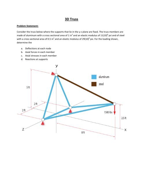
<strong>3D</strong> Truss<br />
Problem Statement:<br />
Consider the <strong>truss</strong> below where the supports that lie in the y‐z plane are fixed. The <strong>truss</strong> members are<br />
made of aluminum with a cross sectional area of 1 in 2 and an elastic modulus of 11(10) 6 psi and of steel<br />
with a cross sectional area of 0.5 in 2 and an elastic modulus of 29(10) 6 psi. For the loading shown,<br />
determine the<br />
a. Deflections at each node<br />
b. Axial forces in each member<br />
c. Axial stresses in each member<br />
d. Reactions at supports
ANSYS Procedure:<br />
1. Preprocessor > Element type > Add/Edit/Delete > (Add) > (Link) > (<strong>3D</strong> spar 8) > OK<br />
2. Preprocessor > Real constants > Add/Edit/Delete > (Add) > Type 1 > OK<br />
(Area = 1, Initial strain = 0) > OK<br />
Add/Edit/Delete > (Add) > Type 1 > OK<br />
(Area =0.5, Initial strain = 0) > OK<br />
3. Preprocessor > Material properties > Material models > Structural > Linear > Elastic > Isotropic<br />
Enter EX = 106 PRXY = 0.3 (Poission’s ratio is not really used for this element)<br />
4. From Material model window menu: Select new model > Define material id 2 > OK<br />
Material properties > Material models > Structural > Linear > Elastic > Isotropic<br />
Enter EX = 296 and PRXY = 0.3<br />
5. Preprocessor > Modeling > Create > Nodes > In active CS<br />
Node x‐coordinate y‐coordinate z‐coordinate<br />
1 0 0 24<br />
2 0 0 ‐24<br />
3 0 60 0<br />
4 96 30 0<br />
6. Utility Menu : Plot ctrls > Numbering > (turn NODE =on)<br />
7. Utility Menu : List > Nodes<br />
8. Utility Menu : Plot ctrls > Pan, Zoom, Rotate ,Click ISO
9. Preprocessor > Modeling > Create ><br />
Elements > Element attributes ( Make sure<br />
Material 1 and Real constant set 1 are<br />
active) for creating aluminum <strong>truss</strong><br />
members<br />
Preprocessor > Modeling > Create ><br />
Elements > Auto numbered > Thru nodes<br />
Element Node Node<br />
1 1 3 Apply<br />
2 3 2 Apply<br />
3 2 1 Apply<br />
4 1 4 Apply<br />
5 2 4 Apply<br />
10. Preprocessor > Modeling > Create ><br />
Elements > Element attributes ( Make sure<br />
Material 2 and Real constant set 2 are<br />
active) for creating the steel member<br />
Preprocessor > Modeling > Create ><br />
Elements > Auto numbered > Thru nodes<br />
Element Node Node<br />
6 3 4 Apply<br />
Applying loads:<br />
11. Solution > Define loads > Apply > Structural<br />
> Displacement > On nodes<br />
Select nodes 1, 2 and 3 > OK > Select “All<br />
DOF” > Constant value >Displacement value<br />
= 0 > OK<br />
12. Solution > Define loads > Apply > Structural<br />
> Force / Moment > On nodes<br />
(Pick node 4 > OK > FY > Constant value ><br />
‐1500 > OK<br />
13. Solution > Solve > Current LS > OK
Post processing:<br />
14. General Postproc > Plot results > Deformed<br />
Shape > (Def + Undef edge) > OK<br />
(notice that the maximum deflection is<br />
0.0637 inches)<br />
15. General Postproc > List results > Nodal<br />
solutions > Nodal solution > DOF solution ><br />
Displacement vector sum > OK<br />
16. General Postproc > Element table > Define table > Add<br />
(AVPRIN =1, lab = axial force > By sequence num > SMISC (enter “,1”) > OK)<br />
17. General Postproc > Element table > Define table > Add<br />
(AVPRIN =1, lab = ax stress > By sequence num > LS (enter “,1”) > OK)
18. General Postproc > Element table > List element table (Select the table you want to list) > OK<br />
19. General Postproc > Element table > Plot element table > Choose the item to plot > OK<br />
20. Utility Menu: List > Elements > Nodes > + Attributes + Real constants<br />
21. General Postproc > List results > Reaction<br />
solution > OK (for support reactions)
Summary of results<br />
1. Deflection at each node<br />
NODE U x (in) U y (in) U z (in) U sum (in)<br />
1 0.0000 0.0000 0.0000 0.0000<br />
2 0.0000 0.0000 0.0000 0.0000<br />
3 0.0000 0.0000 0.0000 0.0000<br />
4 0.67046e‐2 ‐0.63333e‐1 0.0000 0.63687e‐1<br />
2. Axial forces and stresses in each member<br />
Element Axial force (lbs) Axial stress (psi)<br />
1 0.0000 0.0000<br />
2 0.0000 0.0000<br />
3 0.0000 0.0000<br />
4 ‐1292.5 ‐1292.5<br />
5 ‐1292.5 ‐1292.5<br />
6 2514.5 5028.9<br />
3. Reactions at supports<br />
Node F x (lbs) F Y (lbs) F Z (lbs)<br />
1 1200 375 ‐300<br />
2 1200 375 300<br />
3 ‐2400 750 0<br />
This <strong>tutorial</strong> was developed by Sai Ravi Kanth Tummala and David Hall © 2008