G-TEM Cells acc. to IEC/EN 61000-4-20 - R. A. Mayes Company
G-TEM Cells acc. to IEC/EN 61000-4-20 - R. A. Mayes Company
G-TEM Cells acc. to IEC/EN 61000-4-20 - R. A. Mayes Company

You also want an ePaper? Increase the reach of your titles
YUMPU automatically turns print PDFs into web optimized ePapers that Google loves.
G-<strong>TEM</strong> <strong>Cells</strong> <strong>acc</strong>. <strong>to</strong> <strong>IEC</strong>/<strong>EN</strong> <strong>61000</strong>-4-<strong>20</strong><br />
Septum-height: 250mm <strong>to</strong> <strong>20</strong>00mm / 0.1MHz <strong>to</strong> <strong>20</strong>GHz<br />
G-<strong>TEM</strong> <strong>Cells</strong> <strong>acc</strong>. <strong>to</strong> <strong>IEC</strong>/<strong>EN</strong> <strong>61000</strong>-4-<strong>20</strong><br />
PAGE // 6<br />
Description<br />
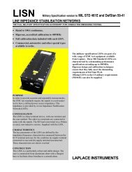
The G<strong>TEM</strong> cell is a <strong>TEM</strong> waveguide with the upper frequency limit extended<br />
<strong>to</strong> the GHz range. It is a low-cost alternative measurement<br />
facility for both radiated emission and immunity measurements. It is<br />
included in the published standard <strong>IEC</strong> <strong>61000</strong>-4-<strong>20</strong> “Emission and<br />
Immunity Testing in Transverse Electromagnetic (<strong>TEM</strong>) Waveguides”.<br />
Compared <strong>to</strong> other measuring methods like EMC test in anechoic chambers<br />
or OATS (Open Area Test Sites), G<strong>TEM</strong> <strong>Cells</strong> offer some significant advantages<br />
for the testing of small and medium sized EUT´s (Equipment<br />
Calculation of the required forward power for radiated immunity tests:<br />
P = (E x h) 2 /R x flatness fac<strong>to</strong>r (2) x modulation fac<strong>to</strong>r (3.24 for 80%AM)<br />
E= required field strength; h=septum height in meter; R= input impedance 50Ω<br />
Under Test) up <strong>to</strong> a frequency range of <strong>20</strong>GHz. Quick turnarounds of<br />
the EUT as well as numerous testing variations are easy and fast <strong>to</strong><br />
handle. Switching from emission <strong>to</strong> immunity testing requires only<br />
simple adjustments, from receiver input <strong>to</strong> amplifier output. You are<br />
irrespective of long waiting times associated with off-site test labs or<br />
weather and ambient delays that can occur at OATS facilities. Whether<br />
you are at the design qualification, pre-compliance, compliance, or<br />
production sampling stage, the G<strong>TEM</strong> is the right choice for you.<br />
Example:<br />
Field strength 10V/m, 80%AM with G<strong>TEM</strong> 1000:<br />
P= (10 x 1.0m) 2 /50 x 2 x 3.24 = 12.96W<br />
Technical specifications 250 500 750 1000<br />
Electrical Data<br />
Input connec<strong>to</strong>r N N N N<br />
Nominal impedance 50 50 50 50<br />
Frequency range, MHz 0,1MHz-<strong>20</strong> GHz 0,1MHz-<strong>20</strong> GHz 0,1MHz-<strong>20</strong> GHz 0,1MHz-<strong>20</strong> GHz<br />
Typical VSWR within frequency range (up <strong>to</strong> 5GHz) 1:1.2 1:1.2 1:1.2 1:1.2<br />
Typical VSWR at critical frequency (up <strong>to</strong> 5GHz) 1:1.6 1:1.6 1:1.6 1:1.6<br />
Max input power, W 250/500 500/1000 600/1<strong>20</strong>0 800/1600<br />
Screening attenuation Typ.: >10KHz50 / >100 >50 / >100 >50 / >100 >50 / >100<br />
Electrical Equipment / Options<br />
Doubled input power<br />
Sockets for EUT 1 2 2 2<br />
Indoor lighting<br />
Channels for fibre optic leads 1 1 1 1<br />
RF feed-thru connec<strong>to</strong>rs N Type 1 2 2 2<br />
RF feed-thru connec<strong>to</strong>rs SMA Type 2<br />
10A / 2 wires (single phase)<br />
Electrical safety interlok<br />
Mains connec<strong>to</strong>rs Fix/CEE Fix/CEE Fix/CEE Fix/CEE<br />
Ground connection M6<br />
AC filter 16A/4 wires<br />
AC filter 25A/4 wires<br />
AC filter 32A/4 wires<br />
AC filter 64A/4 wires<br />
25-pole signal filter (Max.No.)<br />
Video camera system<br />
Mechanical Equipment / Options<br />
Secondary small door next <strong>to</strong> input - -<br />
Window in door (WxH), <strong>20</strong>cm Ø -<br />
Window next <strong>to</strong> door <strong>20</strong>cm Ø<br />
Gas / Water feed through plates<br />
Honeycomb panel<br />
Fans N.2 12x12cm<br />
Light 50W<br />
Mechanical Dimensions / Max. EUT size<br />
Outer (LxWxH), cm 115x64x44 300x165x110 400x2<strong>20</strong>x147 500x276x184<br />
Door (WxH), cm 30x23 42x42 61x61 79x79<br />
Wheeled undercarriage - ○<br />
Weight kg approx. 80 <strong>20</strong>0 400 650<br />
Max. test volume (LxWxH), cm <strong>20</strong>x<strong>20</strong>x15 40x40x30 60x60x50 75x75x70<br />
Defined test vol. ±3dB 15x15x10 30x30x15 45x45x25 60x60x30<br />
Septum height 250mm 500mm 750mm 1000mm<br />
Standard Costed option - Not provided<br />
7 // PAGE
G-<strong>TEM</strong> <strong>Cells</strong> <strong>acc</strong>. <strong>to</strong> <strong>IEC</strong>/<strong>EN</strong> <strong>61000</strong>-4-<strong>20</strong><br />
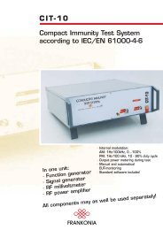
G-<strong>TEM</strong> Optional Accessories<br />
PAGE // 8<br />
Technical specifications 1250 1500 1750 <strong>20</strong>00<br />
Electrical Data<br />
Input connec<strong>to</strong>r 7/16” 7/16” 7/16” 7/16”<br />
Nominal impedance 50 50 50 50<br />
Frequency range, MHz 0,1MHz-<strong>20</strong> GHz 0,1MHz-<strong>20</strong> GHz 0,1MHz-<strong>20</strong> GHz 0,1MHz-<strong>20</strong> GHz<br />
Typical VSWR within frequency range (up <strong>to</strong> 5GHz) 1:1.2 1:1.2 1:1.2 1:1.2<br />
Typical VSWR at critical frequency (up <strong>to</strong> 5GHz) 1:1.6 1:1.6 1:1.6 1:1.6<br />
Max input power, W 800/1600 800/1600 800/1600 800/1600<br />
Screening attenuation Typ.: >10KHz50 / >100 >50 / >100 >50 / >100 >50 / >100<br />
Electrical Equipment / Options<br />
Doubled input power<br />
Sockets for EUT 2 2 2 2<br />
Indoor lighting<br />
Channels for fibre optic leads 1 1 1 1<br />
RF feed-thru connec<strong>to</strong>rs N Type 2 2 2 2<br />
RF feed-thru connec<strong>to</strong>rs SMA Type<br />
10A / 2 wires (single phase)<br />
Electrical safety interlok<br />
Mains connec<strong>to</strong>rs Fix/CEE Fix/CEE Fix/CEE Fix/CEE<br />
Ground connection M8<br />
AC filter 16A/4 wires<br />
AC filter 25A/4 wires<br />
AC filter 32A/4 wires<br />
AC filter 64A/4 wires<br />
25-pole signal filter (Max.No.)<br />
Video camera system<br />
Mechanical Equipment / Options<br />
Secondary small door next <strong>to</strong> input - - ○<br />
Window in door (WxH), 15 x <strong>20</strong>cm -<br />
Window next <strong>to</strong> door (0,30 x 0,10cm)<br />
Gas / Water feed through plates<br />
Honeycomb panel<br />
Fans N.2 12x12cm<br />
Light 50W<br />
Mechanical Dimensions / Max. EUT size<br />
Outer (LxWxH), cm 600x330x2<strong>20</strong> 700x385x257 800x440x293 900x495x330<br />
Door (WxH), cm 100x100 1<strong>20</strong>x1<strong>20</strong> 140x140 160x160<br />
Wheeled undercarriage<br />
Weight kg approx. 850 1000 1300 1650<br />
Max. test volume (LxWxH), cm 95x95x85 1<strong>20</strong>x1<strong>20</strong>x100 140x140x1<strong>20</strong> 160x160x140<br />
Defined test vol. ±3dB 75x75x42 85x85x50 100x100x50 115x115x60<br />
Septum height 1250mm 1500mm 1750mm <strong>20</strong>00mm<br />
Standard Costed option - Not provided<br />
Type I/O ports G<strong>TEM</strong>s MODEL<br />
G<strong>TEM</strong>-B01<br />
EIA 7/8’’ Input Connec<strong>to</strong>r (max. 6GHz)<br />
G<strong>TEM</strong>-B02 EIA 7/16’’ Input Connec<strong>to</strong>r (max. 6GHz)<br />
G<strong>TEM</strong>-B03<br />
700 W Max. Input power, (up <strong>to</strong> 3GHz)<br />
(The max. input power is limited by the spec. of the max<br />
input power of the selected G<strong>TEM</strong>)<br />
G<strong>TEM</strong>-B04 Upgrade Input Power 1400W, (up <strong>to</strong> 3GHz) (The max. input<br />
power is limited by the spec. of the max input power<br />
of the selected G<strong>TEM</strong>)<br />
G<strong>TEM</strong>-B05<br />
G<strong>TEM</strong>-B06 N-Feedthru<br />
G<strong>TEM</strong>-B07<br />
Fibre optical feed-thru (3 Pairs)<br />
SMA-feedthru<br />
Electrical Equipment / Options<br />
G<strong>TEM</strong>-B08<br />
Additional socket for EUT<br />
G<strong>TEM</strong>-B09 Internal illumination (Halogene, 50 W)<br />
G<strong>TEM</strong>-B10<br />
Tube, diameter 5cm, can be closed by screwable cover<br />
G<strong>TEM</strong>-B11 EMI-Filter Upgrade 2x10A <strong>to</strong> 4x32A, 440V/ 250V AC/ DC<br />
G<strong>TEM</strong>-B12 Filter 4 x 32A, 440V/ 250V AC/ DC<br />
G<strong>TEM</strong>-B13<br />
Interlock relay at the door<br />
G<strong>TEM</strong>-B14<br />
DSub Signal Line Filter (25 pin)<br />
G<strong>TEM</strong>-B24<br />
1 pc. Sub-D 9 pin filtered, 1 pc. Sub-D 9 pin unfiltered<br />
G<strong>TEM</strong>-B25 9 pin DSUB Filter<br />
Mechanical Equipment / Options<br />
G<strong>TEM</strong>-B15<br />
Second door close <strong>to</strong> input<br />
G<strong>TEM</strong>-B16<br />
Window in door (Ø <strong>20</strong>0mm)<br />
G<strong>TEM</strong>-B17<br />
Gas/ Waterfeedthru<br />
G<strong>TEM</strong>-B18<br />
Honeycomb<br />
G<strong>TEM</strong>-B19<br />
Fans (2 pieces) on technical panel<br />
G<strong>TEM</strong>-B<strong>20</strong> Door for tests <strong>acc</strong>. <strong>to</strong> SAE J1752/3<br />
G<strong>TEM</strong>-B21<br />
Wheeled undercarriage<br />
G<strong>TEM</strong>-B22<br />
Plastic table, round, d=35cm, max. load: 50kg<br />
G<strong>TEM</strong>-B23<br />
Vertical positioning, turn of door position, plastic table<br />
over pyramids<br />
G<strong>TEM</strong>-B26<br />
Integrated circuit testing<br />
G<strong>TEM</strong>-B27 Installation panel (not equipped)<br />
G<strong>TEM</strong>-B28 Fan kit incl. channel for heat sink<br />
250-500 750-1000-1250-1500<br />
Standard Costed option - Not provided<br />
9 // PAGE
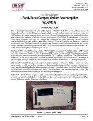
G-<strong>TEM</strong> test set-up for radiated immunity<br />
tests and emission measurements:<br />
G-<strong>TEM</strong> test set-up for radiated immunity<br />
tests and emission measurements:<br />
Relay 1<br />
max.<br />
107 dBµV<br />
Amplifier 1<br />
Directional<br />
Coupler DC1<br />
Relay 2<br />
Power Meter<br />
Channel 1<br />
Genera<strong>to</strong>r<br />
max.<br />
107 dBµV<br />
FLH-1<strong>20</strong>B<br />
Amplifier 2<br />
DC2<br />
C5081<br />
RSU-0243<br />
PMS 1084<br />
R&S SMB 100A<br />
FLG-100A<br />
100-CC<br />
Relay 3<br />
Power Meter<br />
Channel 2<br />
PC<br />
max.<br />
107 dBµV<br />
Amplifier 3<br />
DC3<br />
PMS 1084<br />
RSU-0243<br />
FLG-50F<br />
CPH-274E<br />
RSU-0243<br />
RS232<br />
GPIB<br />
Immunity Software CR-LAB<br />
Emission Software incl. cable<br />
kit and rack installation<br />
RS232<br />
Field strength meter<br />
Relay 4<br />
RSU-0243<br />
GPIB<br />
Radiated Emision and<br />
Radiated Immunity<br />
<strong>acc</strong>. <strong>to</strong><br />
<strong>IEC</strong> / <strong>EN</strong> <strong>61000</strong>-4-<strong>20</strong><br />
(<strong>IEC</strong> / <strong>EN</strong> <strong>61000</strong>-4-3)<br />
G<strong>TEM</strong> 1000<br />
incl. options + Camera FMC<br />
RSU-1<strong>20</strong>3<br />
PAGE // 10<br />
Frequency range:<br />
Emission:<br />
30MHz - 6GHz<br />
Immunity<br />
80MHz - 6 GHz<br />
Test Level: 10V/m incl<br />
80% AM and 30 V/m<br />
Measuring Receiver<br />
11 // PAGE