download the PDF (PDF 200K)
download the PDF (PDF 200K)
download the PDF (PDF 200K)
- No tags were found...

Create successful ePaper yourself
Turn your PDF publications into a flip-book with our unique Google optimized e-Paper software.
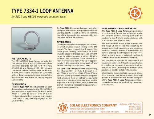
TYPE 7334-1 LOOP ANTENNA<br />
for RE01 and RE101 magnetic emission tests<br />
HISTORICAL NOTE<br />
The AT-205/URM-6 Loop Sensor described in<br />
Test Method RE01 of MIL-STD-462 is one of <strong>the</strong><br />
antennas designed for use with <strong>the</strong> Navy<br />
AN/URM-6B and Stoddart NM-10A receivers.<br />
These were <strong>the</strong> low frequency EMI meters that,<br />
in 1948, initiated <strong>the</strong> emphasis on EMI by <strong>the</strong><br />
military departments and created <strong>the</strong> technical<br />
discipline we now know as Electromagnetic<br />
Compatibility.<br />
DESCRIPTION<br />
The Solar Type 7334-1 Loop Antenna has been<br />
designed as a substitute for <strong>the</strong> AT-205/URM-6<br />
antenna and is a replacement for Eaton Model<br />
94607-1. It uses 36 turns of wire on a 5.25"<br />
(13.3 cm) diameter form enclosed in an electrostatic<br />
shield as described in paragraph 5.2.1 of<br />
MIL-STD-461A.<br />
The Type 7334-1 is equipped with an epoxy-glass<br />
base plate which serves as a spacer to enable <strong>the</strong><br />
user to place <strong>the</strong> loop at exactly 7 cm from <strong>the</strong><br />
face of <strong>the</strong> item under test as required by test<br />
procedure RE01 of MIL-STD-462.<br />
APPLICATION<br />
Connection to <strong>the</strong> loop is through a BNC connector<br />
which enables coaxial cabling to <strong>the</strong> EMI<br />
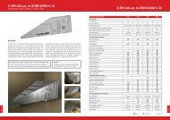
receiver. The loop is supplied with a correction<br />
factor graph showing <strong>the</strong> values in dB which<br />
must be added to <strong>the</strong> reading of a 50 ohm EMI<br />
meter to obtain answers in ei<strong>the</strong>r dB/µV/m<br />
or dB/pT. The correction factor decreases as<br />
frequency increases from 30 Hz up to approximately<br />
15 KHz, where <strong>the</strong> factor levels off and<br />
remains relatively constant up to 5 MHz.<br />
The Type 7334-1 Loop Antenna is required by<br />
Test Method RE01 in Parts 2 through 6 of<br />
MIL-STD-461C and RE101 of MIL-STD-461D.These<br />
portions of <strong>the</strong> specification require magnetic<br />
field emission tests of cables, equipments,<br />
systems and sub-systems installed in, or used in,<br />
all phases of military vehicles, ships, submarines,<br />
aircraft (including helicopters), spacecraft, or<br />
ground-based operations.<br />
TEST METHODS RE01 and RE101<br />
The Type 7334-1 Loop Antenna is positioned<br />
7 cm from <strong>the</strong> face of <strong>the</strong> equipment under<br />
test with <strong>the</strong> plane of <strong>the</strong> loop parallel to <strong>the</strong><br />
equipment face. The best position to begin with<br />
is opposite or near a joint or seam.<br />
The associated EMI meter is <strong>the</strong>n scanned over<br />
<strong>the</strong> range 30 Hz to 100 KHz searching for<br />
emissions. At <strong>the</strong> frequencies where emissions<br />
are found, <strong>the</strong> loop antenna is moved about <strong>the</strong><br />
surface seeking <strong>the</strong> strongest emission level.<br />
When a strong signal is detected, <strong>the</strong> loop is<br />
oriented on its axis for a maximum reading.<br />
This procedure is repeated for all surfaces of <strong>the</strong><br />
equipment under test. Although <strong>the</strong> specification<br />
is not clear on <strong>the</strong> point, it appears to indicate<br />
that all six sides (including <strong>the</strong> bottom) of an<br />
equipment must be tested in this manner.<br />
When testing cables, <strong>the</strong> loop antenna is placed<br />
7 cm from <strong>the</strong> cable with <strong>the</strong> plane of <strong>the</strong> loop<br />
parallel to <strong>the</strong> cable. The non-metallic base plate<br />
of <strong>the</strong> Type 7334-1 Loop Antenna provides a<br />
convenient means for establishing <strong>the</strong> correct<br />
7 cm distance.<br />
47
TYPE 7334-1 LOOP ANTENNA<br />
dB<br />
140<br />
FACTOR IN dB TO BE ADDED TO EMI METER READING IN dB/V<br />
WHEN USING SOLAR TYPE 7334-1 LOOP ANTENNA AS PICKUP DEVICE<br />
dB<br />
140<br />
120<br />
120<br />
100<br />
100<br />
80<br />
FACTOR FOR dB/uV/M<br />
50Ω INPUT<br />
80<br />
60<br />
60<br />
40<br />
FACTOR FOR dB/pT<br />
50Ω INPUT<br />
40<br />
20<br />
20<br />
0<br />
10 Hz 100 Hz 1 KHz 10 KHz 100 KHz<br />
0<br />
48