communicating through the ages - R. A. Mayes Company
communicating through the ages - R. A. Mayes Company
communicating through the ages - R. A. Mayes Company

Create successful ePaper yourself
Turn your PDF publications into a flip-book with our unique Google optimized e-Paper software.
COMMUNICATING THROUGH THE AGESIf you are as “ancient” as I am, you will remember when <strong>the</strong>only two-way communication was by land-line telephone ortelegraph, radio telegraph between ships, and a few specializedcontacts between people. Two-way voice communication beganbetween “hams” and between commercial offices.In <strong>the</strong> early 1920’s radio broadcast stations began to operate.People (like me) built crystal radio receivers using coils woundon oatmeal boxes and using “cat’s whisker” galena detectorsdriving high impedance headphones. I remember connectingthree or four headphones in series on one crystal set so thatseveral people could listen at <strong>the</strong> same time.But nothing is static. All things change. Higher and higherfrequencies were used when vacuum tubes replaced <strong>the</strong> galenadetectors and amplifiers were added to drive cumbersome loudspeakers.In time, television was developed from a spinning diskinto a system using a cathode ray tube to display <strong>the</strong> im<strong>ages</strong>.FM broadcast stations began, touted as noise-free music stations.From <strong>the</strong>se meager, and sometimes painful, beginnings youare now able to communicate with people all over <strong>the</strong> worldvia telephone and FAX, and by electronic mail on your homecomputer. Using <strong>the</strong> Internet or a WEB site you can exploreinnumerable sources of important and vital informationanywhere, any time, for <strong>the</strong> cost of a local telephone call.Technology has proceeded at an exponential rate and <strong>the</strong> endis not in sight.Some of <strong>the</strong> items available in this catalog would not have beenpossible a decade ago. Some call us foolish, but we continueto keep abreast of <strong>the</strong> changes in test requirements forEMI specifications. For example, we have developed tunablemodules (Type 9554 series) which, when used with ourModel 9354-1 Universal Transient Generator, enable testengineers (like you) to apply damped sine wave pulses to a testsample over <strong>the</strong> full range of 10 KHz to 100 MHz at <strong>the</strong> levelsstipulated in MIL-STD-461C/D/E and o<strong>the</strong>r specifications. Theinjection technique requires an Injection Probe, such as ourType 9335-2,to couple <strong>the</strong> pulse onto <strong>the</strong> line.Our day-by-day development of new EMI test equipment andrelated products since 1960 is substantial proof that, “Thereis no substitute for experience”. We would like to hear fromyou because we know we can help with your EMI problems.Communicate with us via telephone, FAX or E-mail.Cordially,Al Parker1
TABLE OF CONTENTSPageCHART — ESSENTIAL APPARATUS FOR PERFORMING TESTS IN ACCORDANCE WITHMIL-STD-461D/E . . . . . . . . . . . . . . . . . . . . . . . . . . . . . . . . . . . . . . . . . . . . . . . . . . . . . . . . . . . . . . . . . . . . . . . . . . . . . . . . . . . . . . . . . . . 7MIL-STD-461A/B/C . . . . . . . . . . . . . . . . . . . . . . . . . . . . . . . . . . . . . . . . . . . . . . . . . . . . . . . . . . . . . . . . . . . . . . . . . . . . . . . . . . . . . . . . . 8Model No.6254-5S6550-16552-1A7054-17054-1A7054-1B7399-27824-18282-18850-19354-19355-19554-( )Type No.6541-17512-17541-18022-18614-19335-29533-1INSTRUMENTSRFI TRANSIENT GENERATOR, 250 volts, 10 microseconds decay time . . . . . . . . . . . . . . . . . . . . . . . . . . . . . . . . . . . . . . . . . . . . . .25POWER SWEEP GENERATOR, 100 watts output . . . . . . . . . . . . . . . . . . . . . . . . . . . . . . . . . . . . . . . . . . . . . . . . . . . . . . . . . . . . . . . . . .31AUDIO POWER AMPLIFIER, 100 watts output . . . . . . . . . . . . . . . . . . . . . . . . . . . . . . . . . . . . . . . . . . . . . . . . . . . . . . . . . . . . . . . . . . .29SPIKE GENERATOR, 600 volts, 10 microseconds decay time . . . . . . . . . . . . . . . . . . . . . . . . . . . . . . . . . . . . . . . . . . . . . . . . . . . . . . .23SPIKE GENERATOR, 400 volts, 50 microseconds decay time . . . . . . . . . . . . . . . . . . . . . . . . . . . . . . . . . . . . . . . . . . . . . . . . . . . . . . .23SPIKE GENERATOR, 400 volts, 120 microseconds decay time . . . . . . . . . . . . . . . . . . . . . . . . . . . . . . . . . . . . . . . . . . . . . . . . . . . . .23SPIKE GENERATOR, 2500 volts, 90 microseconds decay time, meets Appendix A, B, C of MIL-STD-1399 . . . . . . . . . . . . . . .21AUDIO POWER AMPLIFIER (Rack version of 6552-1A) . . . . . . . . . . . . . . . . . . . . . . . . . . . . . . . . . . . . . . . . . . . . . . . . . . . . . . . . . . . .29TRANSIENT PULSE GENERATOR for MIL-STD-461B/C, three waveshapes . . . . . . . . . . . . . . . . . . . . . . . . . . . . . . . . . . . . . . . . . . .19HIGH POWER SWEEP GENERATOR, 200 watts output . . . . . . . . . . . . . . . . . . . . . . . . . . . . . . . . . . . . . . . . . . . . . . . . . . . . . . . . . . . .27UNIVERSAL TRANSIENT GENERATOR, damped sinewave/double exponential . . . . . . . . . . . . . . . . . . . . . . . . . . . . . . . . . . . . . . 9PULSE GENERATOR for MIL-STD-461D, Method CS115 . . . . . . . . . . . . . . . . . . . . . . . . . . . . . . . . . . . . . . . . . . . . . . . . . . . . . . . . . . .17VARIABLE FREQUENCY MODULES . . . . . . . . . . . . . . . . . . . . . . . . . . . . . . . . . . . . . . . . . . . . . . . . . . . . . . . . . . . . . . . . . . . . . . . . . . . . . .13PROBESINDUCTION PROBE, 1.25" I.D. for LEM spec. . . . . . . . . . . . . . . . . . . . . . . . . . . . . . . . . . . . . . . . . . . . . . . . . . . . . . . . . . . . . . . . . . . . . . . .*SPIKE INJECTION PROBE . . . . . . . . . . . . . . . . . . . . . . . . . . . . . . . . . . . . . . . . . . . . . . . . . . . . . . . . . . . . . . . . . . . . . . . . . . . . . . . . . . . . . .77SPIKE INJECTION PROBE . . . . . . . . . . . . . . . . . . . . . . . . . . . . . . . . . . . . . . . . . . . . . . . . . . . . . . . . . . . . . . . . . . . . . . . . . . . . . . . . . . . . . .77CURRENT PROBE FOR CS09 . . . . . . . . . . . . . . . . . . . . . . . . . . . . . . . . . . . . . . . . . . . . . . . . . . . . . . . . . . . . . . . . . . . . . . . . . . . . . . . . . . . . .*F.C.C. "LINE PROBE" (CAPACITY COUPLER) . . . . . . . . . . . . . . . . . . . . . . . . . . . . . . . . . . . . . . . . . . . . . . . . . . . . . . . . . . . . . . . . . . . . . .41IMPEDANCE MATCHING INJECTION PROBE . . . . . . . . . . . . . . . . . . . . . . . . . . . . . . . . . . . . . . . . . . . . . . . . . . . . . . . . . . . . . . . . . . . . .15VOLTAGE PROBE . . . . . . . . . . . . . . . . . . . . . . . . . . . . . . . . . . . . . . . . . . . . . . . . . . . . . . . . . . . . . . . . . . . . . . . . . . . . . . . . . . . . . . . . . . . . .41* Call for details.3
TABLE OF CONTENTS (cont.)RFI/EMI CURRENT PROBES AND INJECTION PROBESPageFOR MEASUREMENT AND/OR INJECTION OF R.F. CURRENT ON WIRES OR CABLES . . . . . . . . . . . . . . . . . . . . . . . . . . . . . . . . . .33Model No.7334-17429-19130-19229-19230-1ANTENNASLOOP ANTENNA, RE01, RE04, RE101 . . . . . . . . . . . . . . . . . . . . . . . . . . . . . . . . . . . . . . . . . . . . . . . . . . . . . . . . . . . . . . . . . . . . . . . . . . . .47LOOP ANTENNA, RS01 . . . . . . . . . . . . . . . . . . . . . . . . . . . . . . . . . . . . . . . . . . . . . . . . . . . . . . . . . . . . . . . . . . . . . . . . . . . . . . . . . . . . . . . .49LOOP ANTENNA . . . . . . . . . . . . . . . . . . . . . . . . . . . . . . . . . . . . . . . . . . . . . . . . . . . . . . . . . . . . . . . . . . . . . . . . . . . . . . . . . . . . . . . . . . . . . .55LOOP SENSOR, RS101 . . . . . . . . . . . . . . . . . . . . . . . . . . . . . . . . . . . . . . . . . . . . . . . . . . . . . . . . . . . . . . . . . . . . . . . . . . . . . . . . . . . . . . . . .45LOOP ANTENNA, RS101 . . . . . . . . . . . . . . . . . . . . . . . . . . . . . . . . . . . . . . . . . . . . . . . . . . . . . . . . . . . . . . . . . . . . . . . . . . . . . . . . . . . . . . .45LINE IMPEDANCE STABILIZATION NETWORKSFOR MEASUREMENT OF EMI VOLTAGE FROM POWER LINES TO GROUND . . . . . . . . . . . . . . . . . . . . . . . . . . . . . . . . . . . . . . . . . .37F.C.C. LINE IMPEDANCE STABILIZATION NETWORKSNETWORKS FOR COMPLIANCE WITH F.C.C. SPECIFICATIONS . . . . . . . . . . . . . . . . . . . . . . . . . . . . . . . . . . . . . . . . . . . . . . . . . . . . . .41LINE IMPEDANCE SIMULATION NETWORKSNETWORKS TO SIMULATE IMPEDANCE OF SPACECRAFT D.C. POWER SYSTEMS . . . . . . . . . . . . . . . . . . . . . . . . . . . . . . . . . . . . .43WAVE FILTERSLOW PASS, HIGH PASS, BANDPASS, BAND REJECT . . . . . . . . . . . . . . . . . . . . . . . . . . . . . . . . . . . . . . . . . . . . . . . . . . . . . . . . . . . . . . . .656512-106R7012-106R7113-106R7314-106R7525-19133-19146-16220-1A6220-26220-47032-17032-2CAPACITORSFEED-THRU CAPACITOR, 10 F, 250 volts @ 400 Hz, 100 amperes . . . . . . . . . . . . . . . . . . . . . . . . . . . . . . . . . . . . . . . . . . . . . . . . .63FEED-THRU CAPACITOR, 10 F, 500 volts @ 400 Hz, 200 amperes . . . . . . . . . . . . . . . . . . . . . . . . . . . . . . . . . . . . . . . . . . . . . . . . .64FEED-THRU CAPACITOR, 10 F, 500 volts @ 400 Hz, 500 amperes . . . . . . . . . . . . . . . . . . . . . . . . . . . . . . . . . . . . . . . . . . . . . . . . .64FEED-THRU CAPACITOR, 10 F, 300 volts @ 400 Hz, 100 amperes . . . . . . . . . . . . . . . . . . . . . . . . . . . . . . . . . . . . . . . . . . . . . . . . .64SERIES CAPACITOR, 0.1 F, BNC connectors . . . . . . . . . . . . . . . . . . . . . . . . . . . . . . . . . . . . . . . . . . . . . . . . . . . . . . . . . . . . . . . . . . . . .69THREE PHASE DELTA CAPACITOR, 10 F . . . . . . . . . . . . . . . . . . . . . . . . . . . . . . . . . . . . . . . . . . . . . . . . . . . . . . . . . . . . . . . . . . . . . . . .68THREE PHASE WYE CAPACITOR, 10 F . . . . . . . . . . . . . . . . . . . . . . . . . . . . . . . . . . . . . . . . . . . . . . . . . . . . . . . . . . . . . . . . . . . . . . . . . . .*TRANSFORMERSAUDIO ISOLATION TRANSFORMER, 50 amperes line current . . . . . . . . . . . . . . . . . . . . . . . . . . . . . . . . . . . . . . . . . . . . . . . . . . . . . .57AUDIO ISOLATION TRANSFORMER, 100 amperes line current . . . . . . . . . . . . . . . . . . . . . . . . . . . . . . . . . . . . . . . . . . . . . . . . . . . . .57HIGH VOLTAGE COUPLING TRANSFORMER . . . . . . . . . . . . . . . . . . . . . . . . . . . . . . . . . . . . . . . . . . . . . . . . . . . . . . . . . . . . . . . . . . . . . .57ISOLATION TRANSFORMER, 115/115 V, 50 to 400 Hz, 800 watts . . . . . . . . . . . . . . . . . . . . . . . . . . . . . . . . . . . . . . . . . . . . . . . .29, 31ISOLATION TRANSFORMER, 230/230 V, 50 to 400 Hz, 800 watts . . . . . . . . . . . . . . . . . . . . . . . . . . . . . . . . . . . . . . . . . . . . . . . . . . .32* Call for details.4
TABLE OF CONTENTS (cont.)Type No.7032-37033-17035-18810-18811-19138-16254-1507115-17115-27332-17406-17802-18282-1508527-18527-28908-19007-17415-37835-8917835-8927835-8968614-19132-19407-16920-0.57144-1.07144-5.07144-10.08415-18525-1TRANSFORMERS (cont.)ISOLATION TRANSFORMER, 124/240 V, 50 to 400 Hz, 800 watts . . . . . . . . . . . . . . . . . . . . . . . . . . . . . . . . . . . . . . . . . . . . . . . . . . .67IMPEDANCE MATCHING TRANSFORMER, 2.4 ohms to 50 ohms . . . . . . . . . . . . . . . . . . . . . . . . . . . . . . . . . . . . . . . . . . . . . . . . . . .31WIDE RANGE TRANSFORMER, 115 V output @ 80 watts (for 6550-1) . . . . . . . . . . . . . . . . . . . . . . . . . . . . . . . . . . . . . . . . . . . . . . .31IMPEDANCE MATCHING TRANSFORMER, 1.5 phms to 50 ohms . . . . . . . . . . . . . . . . . . . . . . . . . . . . . . . . . . . . . . . . . . . . . . . . . . .27WIDE RANGE TRANSFORMER, 115 V output @ 200 watts (for 8850-1) . . . . . . . . . . . . . . . . . . . . . . . . . . . . . . . . . . . . . . . . . . . . .27STEP UP 2KV, 3 KHz to 30 KHz . . . . . . . . . . . . . . . . . . . . . . . . . . . . . . . . . . . . . . . . . . . . . . . . . . . . . . . . . . . . . . . . . . . . . . . . . . . . . . . . .27PULSE TRANSFORMERSPULSE TRANSFORMER, 150 ampere secondary (Use with 6254-5S or 7054-1) . . . . . . . . . . . . . . . . . . . . . . . . . . . . . . . . . . . . . .26PULSE TRANSFORMER, 15 KV (Use with 6254-5S) . . . . . . . . . . . . . . . . . . . . . . . . . . . . . . . . . . . . . . . . . . . . . . . . . . . . . . . . . . . . . . . 71PULSE TRANSFORMER, 15 KV (Use with 8282-1) . . . . . . . . . . . . . . . . . . . . . . . . . . . . . . . . . . . . . . . . . . . . . . . . . . . . . . . . . . . . . . . . .71PULSE TRANSFORMER (Use with 7054-1A, step up to 600 V into 6 ohms) . . . . . . . . . . . . . . . . . . . . . . . . . . . . . . . . . . . . . . . . . .24PULSE TRANSFORMER (Use with 7054-1A, step up to 1200 V into 50 ohms) . . . . . . . . . . . . . . . . . . . . . . . . . . . . . . . . . . . . . . .24PULSE TRANSFORMER (Use with 6254-5S, step up to 450 V into 12 ohms) . . . . . . . . . . . . . . . . . . . . . . . . . . . . . . . . . . . . . . . . .26PULSE TRANSFORMER, 150 ampere secondary (Use with 8282-1) . . . . . . . . . . . . . . . . . . . . . . . . . . . . . . . . . . . . . . . . . . . . . . . . .20PULSE TRANSFORMER (Use with 7054-1, step up to 2 KV into 50 ohms) . . . . . . . . . . . . . . . . . . . . . . . . . . . . . . . . . . . . . . . . . . .24PULSE TRANSFORMER (Use with 8282-1, step up to 2 KV into 50 ohms) . . . . . . . . . . . . . . . . . . . . . . . . . . . . . . . . . . . . . . . . . . .20PULSE TRANSFORMER, plugs into 8282-1 to provide 600 V from 50 ohm source . . . . . . . . . . . . . . . . . . . . . . . . . . . . . . . . . . .20PULSE TRANSFORMER, plugs into 8282-1 to provide 1200 volts from 50 ohm source, 0.15 S . . . . . . . . . . . . . . . . . . . . . . .20COUPLING NETWORKSR.F. COUPLING AND HIGH PASS FILTER, 50 KHz to 400 MHz, 270 V.A.C. . . . . . . . . . . . . . . . . . . . . . . . . . . . . . . . . . . . . . . . . . . . .69COUPLING NETWORK, equivalent to CU-891/URM-85, 50 ohms . . . . . . . . . . . . . . . . . . . . . . . . . . . . . . . . . . . . . . . . . . . . . . . . . .67COUPLING NETWORK, equivalent to CU-892/URM-85, 500 ohms . . . . . . . . . . . . . . . . . . . . . . . . . . . . . . . . . . . . . . . . . . . . . . . . .67COUPLING NETWORK, equivalent to CU-896/URM-85, 50 ohms . . . . . . . . . . . . . . . . . . . . . . . . . . . . . . . . . . . . . . . . . . . . . . . . . .67COUPLING NETWORK, "LINE PROBE" FOR F.C.C. . . . . . . . . . . . . . . . . . . . . . . . . . . . . . . . . . . . . . . . . . . . . . . . . . . . . . . . . . . . . . . . . .41R.F. COUPLER AND HIGH PASS FILTER, 500 V.A.C. . . . . . . . . . . . . . . . . . . . . . . . . . . . . . . . . . . . . . . . . . . . . . . . . . . . . . . . . . . . . . . . .69THREE PHASE R.F. COUPLING NETWORK, 2 MHz to 30 MHz . . . . . . . . . . . . . . . . . . . . . . . . . . . . . . . . . . . . . . . . . . . . . . . . . . . . . .69RESISTIVE DEVICESRESISTIVE NETWORK, 0.5 ohm . . . . . . . . . . . . . . . . . . . . . . . . . . . . . . . . . . . . . . . . . . . . . . . . . . . . . . . . . . . . . . . . . . . . . . . . . . . . . . . . .67PRECISION RESISTOR, 1.0 ohm, 50 watts . . . . . . . . . . . . . . . . . . . . . . . . . . . . . . . . . . . . . . . . . . . . . . . . . . . . . . . . . . . . . . . . . . . . . . . .67PRECISION RESISTOR, 5.0 ohms, 50 watts . . . . . . . . . . . . . . . . . . . . . . . . . . . . . . . . . . . . . . . . . . . . . . . . . . . . . . . . . . . . . . . . . . . . . . . .*PRECISION RESISTOR, 10.0 ohms, 50 watts . . . . . . . . . . . . . . . . . . . . . . . . . . . . . . . . . . . . . . . . . . . . . . . . . . . . . . . . . . . . . . . . . . . . . .67PRECISION SHUNT RESISTOR, .001 ohm, 0.25%, 100 amperes . . . . . . . . . . . . . . . . . . . . . . . . . . . . . . . . . . . . . . . . . . . . . . . . . . 29NON-INDUCTIVE LOAD RESISTOR, 5.0 ohms, 5%, 2 watts . . . . . . . . . . . . . . . . . . . . . . . . . . . . . . . . . . . . . . . . . . . . . . . . . . . . . . .24* Call for details.Page5
TABLE OF CONTENTS (cont.)Type No.8814-1.58814-2.49224-1.09225-0.59226-0.57510-17519-18121-18128-18806-18801-1.6— —— —PageRESISTIVE DEVICES, cont.RESISTIVE LOAD, 300 watt 1.5 ohm load for normalizing <strong>the</strong> impedance of <strong>the</strong> 6220-1A Transformer . . . . . . . . . . . . . . . .68RESISTIVE LOAD, 200 watt 2.4 ohm load for normalizing <strong>the</strong> impedance of <strong>the</strong> 6220-1A Transformer . . . . . . . . . . . . . . . .68PRECISION RESISTOR, 1.0 ohm, 1%, for use in CE101 tests . . . . . . . . . . . . . . . . . . . . . . . . . . . . . . . . . . . . . . . . . . . . . . . . . . . . . . . . .*PRECISION RESISTOR, 0.5 ohms, 1%, for use in CS101 tests . . . . . . . . . . . . . . . . . . . . . . . . . . . . . . . . . . . . . . . . . . . . . . . . . . . . . . . .*PRECISION RESISTOR, 0.5 ohms, 1%, for use in CS109 tests . . . . . . . . . . . . . . . . . . . . . . . . . . . . . . . . . . . . . . . . . . . . . . . . . . . . . . . .*MISCELLANYSPARK GAP, NEEDLE AND SPHERICAL . . . . . . . . . . . . . . . . . . . . . . . . . . . . . . . . . . . . . . . . . . . . . . . . . . . . . . . . . . . . . . . . . . . . . . . . . . .71PULSE SHAPING NETWORK (Use with 7512-1 for 100 S spike) . . . . . . . . . . . . . . . . . . . . . . . . . . . . . . . . . . . . . . . . . . . . . . . . . . .77ADAPTER FOR TYPE 7021-1 PHASE SHIFT NETWORK, 200 amperes . . . . . . . . . . . . . . . . . . . . . . . . . . . . . . . . . . . . . . . . . . . . . . .67ADAPTER TO CONVERT TWO TYPE 8028-50-TS-24-BNC LISNs TO A DUAL UNIT . . . . . . . . . . . . . . . . . . . . . . . . . . . . . . . . . . . . .67PULSE STRETCHING NETWORK, (Use with 8282-1 and 7406-1 to obtain 1000 volts, 20 S into 50 ohms) . . . . . . . . . . . . .68INDUCTOR, 1.6 mH, 10 amps, V.D.E. 0871 A1/APR 84 . . . . . . . . . . . . . . . . . . . . . . . . . . . . . . . . . . . . . . . . . . . . . . . . . . . . . . . . . . . . .68CALIBRATION FIXTURES . . . . . . . . . . . . . . . . . . . . . . . . . . . . . . . . . . . . . . . . . . . . . . . . . . . . . . . . . . . . . . . . . . . . . . . . . . . . . . . . . . . . . . .35ENGINEER’S CLOCK . . . . . . . . . . . . . . . . . . . . . . . . . . . . . . . . . . . . . . . . . . . . . . . . . . . . . . . . . . . . . . . . . . . . . . . . . . . . . . . . . . . . . . . . . . .79APPLICATION INFORMATIONTYPE 6693-3L/3R-DC ISOLATOR NETWORK . . . . . . . . . . . . . . . . . . . . . . . . . . . . . . . . . . . . . . . . . . . . . . . . . . . . . . . . . . . . . . . . . . . . .75TYPE 7021-1 PHASE SHIFT NETWORK . . . . . . . . . . . . . . . . . . . . . . . . . . . . . . . . . . . . . . . . . . . . . . . . . . . . . . . . . . . . . . . . . . . . . . . . . .73TYPE 7429-1 LOOP ANTENNA . . . . . . . . . . . . . . . . . . . . . . . . . . . . . . . . . . . . . . . . . . . . . . . . . . . . . . . . . . . . . . . . . . . . . . . . . . . . . . . . .51TYPE 9130-1 LOOP ANTENNA . . . . . . . . . . . . . . . . . . . . . . . . . . . . . . . . . . . . . . . . . . . . . . . . . . . . . . . . . . . . . . . . . . . . . . . . . . . . . . . . .56TYPE 9229-1 and 9230-1 LOOP ANTENNAS . . . . . . . . . . . . . . . . . . . . . . . . . . . . . . . . . . . . . . . . . . . . . . . . . . . . . . . . . . . . . . . . . . . . .46HIGH VOLTAGE SPARK TESTS USING TYPE 7115-1 OR 7115-2HIGH VOLTAGE TRANSIENT PULSE TRANSFORMER AND TYPE 7510-1 SPARK GAP . . . . . . . . . . . . .71TYPE 7415-3 R.F. COUPLER AND HIGH PASS FILTER . . . . . . . . . . . . . . . . . . . . . . . . . . . . . . . . . . . . . . . . . . . . . . . . . . . . . . . . . . . . . .69CABLE INDUCED TRANSIENTS FOR SPACE SHUTTLE PROGRAM . . . . . . . . . . . . . . . . . . . . . . . . . . . . . . . . . . . . . . . . . . . . . . . . . . .77USING THE 6220-1A TRANSFORMER FOR THE MEASUREMENT OF LOW FREQUENCY EMI CURRENTS . . . . . . . . . . . . . . . . .59CALIBRATION OF LOOP ANTENNAS . . . . . . . . . . . . . . . . . . . . . . . . . . . . . . . . . . . . . . . . . . . . . . . . . . . . . . . . . . . . . . . . . . . . . . . . . . . .53EMI PREDICTION GRAPH . . . . . . . . . . . . . . . . . . . . . . . . . . . . . . . . . . . . . . . . . . . . . . . . . . . . . . . . . . . . . . . . . . . . . . . . . . . . . . . . . . . . . .81* Call for details.6
ESSENTIAL APPARATUS FOR PERFORMING TESTS PER MIL-STD-461D/ETYPE NO. DESCRIPTION6220-1A Audio Isolation Transformer6220-2 Audio Isolation Transformer7032-1 Isolation Transformer, 800 W.7032-2 Isolation Transformer, 800 W.7334-1 Loop Antenna7720-( ) High Pass Filter, 50 ohms8231-*/* Band Reject Filter, 50 ohms8850-1 High Power Sweep Generator, 200 W.9123-1N Current Probe, 10 KHz-500 MHz9125-1 Calibration Fixture, Injection Probe9133-1 ‘Delta’ Capacitor Assembly9142-1N Injection Probe, 2MHz-450 MHz9144-1N Injection Probe, 10 KHz-200 MHz9146-1 ‘Wye’ Capacitor Assembly9207-1 Current Probe, 20 Hz-150 MHz9224-1.0 Precision Resistor, 1.0 ohms9225-0.5 Precision Resistor, 0.5 ohms9226-0.5 Precision Resistor, 0.5 ohms9229-1 Loop Sensor9230-1 Radiating Loop9233-50-TS-50-N LISN9335-2 Multi-Port Coupling Device9357-2 Calibration Fixture9410-1 H.V. Attenuator9454-1 H.V. Attenuator9354-1 Universal Transient Generator9355-1 Pulse Generator9401-1 10 pF Series CapacitorCE CE CS CS CS CS CS RE RE RE RS RS RS101 102 101 109 114 115 116 101 102 103 101 103 105NOTE:x 1x 2x 3x 4Type 6220-1A is rated at 50 amperessecondary current.Type 6220-2 is rated at 100 amperessecondary current.Type 7032-1 is rated at 120 volts, 50-400 Hz,800 W.Type 7032-2 is rated at 240 volts, 50-400 Hz,800 W.High pass filters can be supplied up to50 MHz, 50 ohms.Band reject filters can be supplied up to50 MHz, 50 ohms.Test may require variable frequency modulesType 9554-10K/100KType 9554-100K/1MType 9554-1M/16MType 9554-6M/50MType 9754-35M/85M step frequency module7
ESSENTIAL APPARATUS FOR PERFORMING TESTSin accordance with MIL-STD-461A/B/CTYPE NO. DESCRIPTION6220-1A Audio Isolation Transformer6254-5S RFI Transient Generator, 10S6338-5-PJ-50-N LISN6338-57-PJ-50-N LISN6512-106R Feed-thru Capacitor, 10 F6550-1 Power Sweep Generator, 100 W.6552-1A Audio Amplifier, 100 W.6623-( ) Low Pass Filter, 50 ohms6741-1 EMI Current Probe6920-0.5 Resistive Network7021-1 Phase Shift Network7032-1 (or -2) Isolation Transf., 800W.7054-1 Spike Generator, 10 S7054-1A Spike Generator, 50 S7144-1.0 Precision Resistor, 1.0 ohm7144-10.0 Precision Resistor, 10.0 ohms7205-( ) High Pass Filter, 50 ohms7334-1 Loop Sensor7415-3 R.F. Coupler-High Pass Filter7429-1 Loop Antenna7835-891 Coupling Network7835-892 Coupling Network7835-896 Coupling Network8022-1 Current Probe8282-1 Spike Generator, .15/5/10 S8309-5-TS-100-N LISN8415-1 Precision Resistor, .001 ohm8850-1 Power Sweep Generator, 200 W.9354-1 Transient GeneratorCE CE CE CE CE CE CE CS CS CS CS CS CS CS CS CS01 02 03 04 05 06 07 01 02 03 04 05 06 08 09 10CS CS CS RE RE RE RE RE RE RS RS RS RS RS RS11 12 13 01 02 03 04 05 06 01 02 03 04 05 06NOTE: x 1 . See Notice 3, MIL-STD-462 for CE01 x 3 . Used on B1 aircraft susceptiblity tests.in lieu of current probe. x 4 . Supplies all 3 waveshapes of MIL-STD-461B/C.x 2 . Required by Notice 3, MIL-STD-462, x 5 . Used for Part 2 and 4, U.S. Army (only)U.S. Army Contracts and Notices 5, x 6 . For five microhenry applications above 50 amps.MIL-STD-462, U.S. Navy Contracts.8
MODEL 9354-1 UNIVERSAL TRANSIENT GENERATORfor susceptibility tests MIL-STD461C/D/E, DO-160C/D and o<strong>the</strong>r specificationsAPPLICATIONThe Model 9354-1 Universal TransientGenerator was especially designed for <strong>the</strong>performance of a variety of pulse susceptibilitytests on subsystems and/or equipment, inaccordance with MIL-STD-461D and E, methodCS116; RTCA DO160D, section 22; MIL-STD-461C,methods CS10 and CS11.Through <strong>the</strong> use of many Solar accessories,including various reactive networks and couplingdevices, as well as o<strong>the</strong>r commercially availableitems such as loop antennas, parallel plates,and TEM cells, <strong>the</strong> generated output may bemodified and applied to o<strong>the</strong>r specifications.(Contact Solar customer service for details.)DESCRIPTIONModel 9354-1 Universal Transient Generatorprovides nine selectable waveforms, includingsix damped sinusoidal pulses (10 KHz, 100 KHz,1 MHz, 10 MHz, 30 MHz, and 100 MHz) andthree double exponential pulses (6.4 S, 70 Sand 500 S).Auto pulsing of <strong>the</strong> sinusoidal repetition rateis internally adjusted from 0.5 to 1.0 pulse persecond. A front panel-mounted push button canbe used to manually trigger single pulses. Thepeak amplitude of <strong>the</strong> selected output pulse isadjustable as a percentage of <strong>the</strong> charge voltage.The six damped sinusoidal waveforms weredesigned to meet <strong>the</strong> requirements ofMIL-STD-461D and E, method CS116, whenapplied in accordance with <strong>the</strong> test method ofMIL-STD-462D. Continuous tunable frequenciescan be obtained by <strong>the</strong> use of <strong>the</strong> optionalvariable frequency modules.These same waveforms are applicable to <strong>the</strong>requirements of MIL-STD-461C, methods CS10and CS11, when applied in accordance with <strong>the</strong>test method of MIL-STD-462, Notice 5.The 1MHz and 10 MHz damped sinusoidalwaveforms have been extended to a peak opencircuit voltage of 3200 volts and a calculatedshort circuit current of 128 amperes to meet<strong>the</strong> requirements of RTCA DO-160D, Section 22,Table 22-2, waveform 3.The three double exponential pulses weredesigned to meet <strong>the</strong> requirements of RTCADO-160D, Section 22, Tables 22-2 and 22-3.Table 1 lists <strong>the</strong> test level that can be achievedfrom <strong>the</strong> Model 9354-1.FEATURES■ Panel-mounted digital voltmeter. Monitors <strong>the</strong>adjusted open circuit discharge voltage.■ Pulse rates up to two pulses per secondmaximum (factory adjusted).■ Single pulse feature enables controlledisolation of transient effects.■ Output voltage adjustable from 0.1% to 100%of selected discharge voltage.Table 1: DO-160D Test Levels possiblefrom Model 9354-1Waveform Pin Injection Cable BundleInjection1 (70 S) no requirement level 1- 42 (6.4 S) no requirement level 1 - 43 (1MHz & level 1 - 5 level 1 - 410 MHz)4 (70 S) level 1 - 5 level 1 - 45B (500 S) level 1 - 4 level 1 - 39
MODEL 9354-1 UNIVERSAL TRANSIENT GENERATORDOUBLE EXPONENTIAL PULSES(NOTE: MEASUREMENT OF SHORT CIRCUIT CUR-RENTS ARE LIMITED BY THE X L OF THE CIRCUIT.ALL VALUES ARE CALCULATED.)6.4 SRise Time . . . . . . . . . . . . . . . . . . . . . . . . . . . . . .100 nS.Open Circuit Voltage . . . . . . . . . . . . . . . . . . . .1600 V.Calculated Short Circuit Current . . . . . . . . .800 A.Source Impedance . . . . . . . . . . . . . . . . . . . . . .
MODEL 9554-( ) VARIABLE FREQUENCY MODULESfor use with Model 9354-1 Universal Transient Generator as required byMethod CS-116, MIL-STD-461 Rev. DAPPLICATIONUtilizing <strong>the</strong> high voltage power source in <strong>the</strong>Model 9354-1 Universal Transient Generator,four individual modules can be connectedto provide tuning of damped sine waves from10 KHz to 50 MHz. A fifth module is availablewhich, when used in conjunction with <strong>the</strong> Model9354-1, provides 20% frequency steps from30 MHz to 100 MHz.DESCRIPTIONIndividual modules enable tuning of damped sinewaves in accordance with <strong>the</strong> requirement ofMethod CS-116, MIL-STD-461 Rev. D. The partnumber of each module indicates <strong>the</strong> frequencyrange of <strong>the</strong> module. For example, P/N Type9554-10K/100K indicates a range of 10 KHz to100 KHz. The five modules are identified as:Type 9554-10K/100K variable frequency moduleType 9554-100K/1M variable frequency moduleType 9554-1M/6M variable frequency moduleType 9554-6M/50M variable frequency moduleType 9754-35M/85M step frequency moduleTwo cables connect <strong>the</strong> module to <strong>the</strong> Model9354-1. One cable is a single insulated wire tocarry high voltage d.c. to <strong>the</strong> module. The o<strong>the</strong>rcable delivers low voltage d.c. to <strong>the</strong> module foroperation of relays.OPERATIONThe test setup for calibration of test waveform isindicated in Figure CS116-1, page 79 of MIL-STD-462D. To achieve <strong>the</strong> required injection current,<strong>the</strong> digital display on <strong>the</strong> front panel of <strong>the</strong> Model9354-1 can be recorded during <strong>the</strong> calibrationstep for reference and repeated when <strong>the</strong> actualtest setup is in accordance with Figure CS116-3,page 81 of MIL-STD-462D. This calibration mustbe repeated at each test frequency.The frequency of <strong>the</strong> damped sine wave isadjusted by a tuning control on <strong>the</strong> panel of <strong>the</strong>module. A graph showing frequency versus turnscount on <strong>the</strong> tuning control is supplied.With <strong>the</strong> selected module connected, <strong>the</strong> chargevoltage of <strong>the</strong> module is adjusted by <strong>the</strong> AMPLI-TUDE control on <strong>the</strong> Model 9354-1 UniversalTransient Generator.The AMPLITUDE knob ismarked in percentage of <strong>the</strong> available chargevoltage for <strong>the</strong> module being used.The amplitude and frequency of <strong>the</strong> damped sinewave into <strong>the</strong> load can be determined by anassociated oscilloscope with a 50 ohm input.After <strong>the</strong> charge voltage is adjusted to <strong>the</strong> desiredvalue, <strong>the</strong> damped sine wave is applied to <strong>the</strong>load by pushing <strong>the</strong> button on <strong>the</strong> module.USEFUL ACCESSORIESType 9125-1 Calibration JigType 9142-1N Injection ProbeType 9357-1 Calibration JigType 9335-2 Multiple Impedance CouplingDeviceType 9410-1 High Voltage Attenuator (Theinput to <strong>the</strong> Type 9410-1 can be used for a50 ohm coaxial load as required by MIL-STD-462DFigure CS116-1.)Type 9841-1 1000 Volt Termination, 50 ohmcoaxial 1 W average power. Typical input VSWR ina 50 ohm system under 1.5 from DC to 1 GHz.13
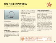
TYPE 9335-2 MULTIPLE IMPEDANCE COUPLING DEVICEimpedance matching injection probeAPPLICATIONVarious EMI specifications require <strong>the</strong> injectionof high level voltage or current pulses and <strong>the</strong>reception of low level voltage or current emissionsusing a toroidal transformer or couplingdevice around <strong>the</strong> interconnecting conductors of<strong>the</strong> subsystems/equipment being tested.The Type 9335-2 Multiple Impedance CouplingDevice is a split toroid, designed as a versatileimpedance matching transformer used in conjuctionwith a generator as an injection probe forconducted susceptibility tests such as methodsCS10 and CS11 of MIL-STD-462, Notice 5; CS116 ofMIL-STD-462D; DO-160C, Section 22, Figure 22-12;and o<strong>the</strong>r specifications.INJECTION – High power transient generatorswith source impedances from 0.25 to 50 can use this probe to deliver high peak voltageor high current pulses into <strong>the</strong> wires or cablespassing <strong>through</strong> <strong>the</strong> window of <strong>the</strong> device.DESCRIPTIONThe unique winding arrangement of this impedancematching probe* provides step-up or stepdownratios with respect to ei<strong>the</strong>r: 1) <strong>the</strong> sourceimpedance of <strong>the</strong> connected generator, whenused for injection, or 2) <strong>the</strong> load impedance of<strong>the</strong> connected receiver, when used for reception.This results in maximum power transfer intoor out of <strong>the</strong> transformer winding formed by<strong>the</strong> cable bundle passing <strong>through</strong> <strong>the</strong> window.The Type 9335-2 Multiple Impedance CouplingDevice provides:1:1.0 voltage or current transfer1:1.5 voltage step-up or current step-down2:1.0 voltage step-down or current step-up1:3.0 voltage step-up or current step-downThese ratios are selected by connecting to oneof <strong>the</strong> four BNC connectors on <strong>the</strong> side of <strong>the</strong>Type 9335-2.Figure 1 shows a family of curves representing <strong>the</strong>transfer functions for each connector port when<strong>the</strong> device is used as an injection probe.Through connector port selection, <strong>the</strong> opencircuit voltage or short circuit current can beadjusted for maximum transfer of energy. This isespecially useful as an accessory to <strong>the</strong> Model9354-1 Universal Transient Pulse Generatorwith its differing source impedances, enablingit to meet various open circuit voltage, and shortcircuit current requirements.CALIBRATIONFor proper calibration of current probes, a specialtest fixture must be used to maintain a 50 ohmcharacteristic impedance for <strong>the</strong> test signal as itpasses <strong>through</strong> <strong>the</strong> window of <strong>the</strong> probe.The design of <strong>the</strong> Type 9357-1 CalibrationFixture was carefully tailored to provide a 50 ohmcharacteristic impedance based on <strong>the</strong> specificdimensions of <strong>the</strong> Type 9335-2. The fixturemaintains a low standing wave ratio from 10 KHzto 10 MHz in a 50 ohm circuit.* We refer to this unique device as <strong>the</strong> KnollerProbe, since it is <strong>the</strong> brainchild of Hank Knoller,an EMC engineer with more than forty yearsexperience in <strong>the</strong> design and application ofequipment for EMI testing.15
TYPE 9335-2 MULTIPLE IMPEDANCE COUPLING DEVICEdB0PORT 4 (1:3) Rs: 1.2 OHMSPORT 3 (1:1.5) Rs: 2.4 OHMS1020PORT 2 (2:1) Rs: 50 OHMSPORT 1 (1:1) Rs: 25 OHMS30Rs: GENERATOR SOURCE IMPEDANCE1 2 3 4 5 6 7 8 9 1 2 3 4 5 6 7 8 9 1 2 3 4 5 6 7 8 9 1 2 3 4 5 6 7 8 9 1010 KHz 100 KHz 1 MHz 10 MHz 100 MHzFIG. 1. INJECTION TRANSFER FUNCTION FOR SEVERAL GENERATOR SOURCE IMPEDANCES.RF GENERATORR S16RF VOLTMETER50 ΩPROBECALIBRATION FIXTURE50 ΩTERMINATIONINJECTION PROBE CALIBRATION
MODEL 9355-1 PULSE GENERATORfor MIL-STD461D/E CS115 susceptibility testAPPLICATIONSolar Model 9355-1 Pulse Generator isdesigned to provide impulse excitation bymeans of an injection probe placed aroundinterconnecting cables or power wires. The unituses a charged transmission line (50 ohms) togenerate a pulse with less than 2 nanosecondsrise and fall time, and duration of approximately30 nS, calibrated in a 50 ohm fixture to deliver upto 5 amperes at a rate of 30 p.p.s. for one minute asrequired by MIL-STD-461D/E, test method CS115.DESCRIPTIONThe charged line potential of <strong>the</strong> Model 9355-1is adjustable from less than 2 volts to greater than2000 volts. The repetition rate is variable fromless than 0.6 p.p.s. to greater than 150 p.p.s.,or single pulses manually triggered by a panelmounted push button. Digital displays monitor<strong>the</strong> charging voltage and pulse repetition rate.This unit can also be used as an impulsecalibrator to provide an adjustable spectraloutput up to 150 dB V/MHz over <strong>the</strong> frequencyrange of 1 KHz to 10 MHz constant within 1 dB.SPECIFICATIONSOUTPUT PULSE:Charging Voltage: Adj. from 0 to 2000 voltsRise/Fall Time: 2000 V.■ Pulse generator with spectral outputcalibrated in terms of dB V/MHz into a50 ohm load.ACCESSORIES RECOMMENDED FORCS115 TESTINGType 9233-50-TS-50-N Line Impedance StabilizationNetwork.Type 9125-1 Calibration Fixture used tocalibrate probes with a window size from 1.25" to1.50" and a frequency range of 20 Hz to 500 MHz.Type 9142-1N Current Injection Probe with afrequency range of 2 MHz to 450 MHz, 200 W.Type 9123-1 Current Monitor Probe with afrequency range of 10 KHz to 500 MHz, 1.25"window.Type 9410-1 High Voltage 40 dB Attenuator,dc to 1 GHz, 40 dB insertion loss, 2 dB. Can alsobe used as a high voltage, 50 ohm coaxial load.Type 9841-1 1000 Volt Termination, 50 ohmcoaxial 1 W average power. Typical input VSWR ina 50 ohm system under 1.5 from DC to 1 GHz.17
MODEL 8282-1 TRANSIENT PULSE GENERATORfor conducted transient susceptibility testing, 0.15 S - 5.0 S - 10.0 S up to 600 volts (peak)APPLICATIONThe Model 8282-1 Transient Pulse Generatorwas designed for screen room use in makingconducted spike susceptibility tests. It providesall <strong>the</strong> waveshapes required by MIL-STD-461B/Cand many o<strong>the</strong>r military EMI specifications.DESCRIPTIONSpike generators required for susceptibilitytesting have been our specialty since 1962, whenour first unit, <strong>the</strong> Model 6254-1,was introduced.The Model 8282-1 incorporates all <strong>the</strong> flexibilityand technical excellence of <strong>the</strong> previous modelsand provides features required by specificationMIL-STD-461B/C.Three different spike durations are provided:0.15 S, 5.0 S, and 10.0 S. The pulse shapeapproximates <strong>the</strong> curve of Figure 19 in MIL-STD-462. The amplitude of <strong>the</strong> spike voltage is fullyadjustable and is displayed on an LED meter.In <strong>the</strong> series injection mode on 50, 60 or 400 Hzlines, a phase adjustment allows <strong>the</strong> spike tobe positioned anywhere on <strong>the</strong> sine wave of<strong>the</strong> power line. This feature makes possible <strong>the</strong>injection of interfering transients at selectedpoints in time to determine <strong>the</strong> susceptibility ofsystems which depend upon frequency or time.The repetition rate of <strong>the</strong> spike can be adjustedwith a panel control to any rate from 0.5 to 50p.p.s. A single pulse can be injected with <strong>the</strong> aidof a panel-mounted pushbutton.All functions are selected by pushbuttons whichare lighted when activated.The Model 8282-1 Transient Pulse Generatorprovides up to 600 volts peak amplitude foreach of <strong>the</strong> 0.15, 5.0 and 10.0 S spikes. Theoutput voltage rises steeply to peak amplitudeas adjusted by <strong>the</strong> panel control, <strong>the</strong>n fallsexponentially to cross <strong>through</strong> zero at <strong>the</strong>duration of 0.15, 5.0, or 10.0 S as selected bypushbuttons. The voltage falls below zero and“rings” for a period determined by <strong>the</strong> inductancein <strong>the</strong> output circuit or <strong>the</strong> load. The peak amplitudedisplayed on <strong>the</strong> LED meter is <strong>the</strong> valuethat would appear across a 5.0 ohm noninductiveload.With series injection on 50, 60 or 400 Hz powerlines, <strong>the</strong> spike can be applied to ei<strong>the</strong>r <strong>the</strong>positive or negative half cycle of <strong>the</strong> powerfrequency sine wave. The spike can be adjustedto fall on <strong>the</strong> power sine wave from 0 to 360.For non-synchronous injection, <strong>the</strong> repetitionrate can be adjusted from 0.5 to 50 p.p.s.A pushbutton enables <strong>the</strong> “single spike” featureand <strong>the</strong> spike can be manually triggered bypushing ano<strong>the</strong>r button. A connector on <strong>the</strong>rear panel makes provision for remote triggeringof <strong>the</strong> single spike feature.Two methods of remote triggering are provided.One method requires <strong>the</strong> application of 24 voltsd.c. to trigger <strong>the</strong> pulse at rates determined byan external switch up to 550 p.p.s. The secondmethod requires <strong>the</strong> application of a square wavewhich can be used to trigger <strong>the</strong> spike up to50 p.p.s. for <strong>the</strong> 0.15 S spike and up to 1000 p.p.s.for <strong>the</strong> 5.0 and 10.0 S spikes. This latter featurecan be used to trigger <strong>the</strong> spike in sync with somefunction within <strong>the</strong> equipment under test.FEATURES■ Provides outputs up to 600 volts peakamplitude for <strong>the</strong> 0.15, 5.0 and 10.0 S spikesinto a five ohm resistive load (low sourceimpedance).■ A wide range of repetition rates allows spikeinjection in terms of <strong>the</strong> pulse rates of itemsbeing tested.■ The single pulse feature enables controlledisolation of transient effects.19
MODEL 8282-1 TRANSIENT PULSE GENERATOR■ Adjustable pulse position on a.c. power linesrelates <strong>the</strong> transient susceptibility to <strong>the</strong> realtime aspects of digital circuitry served bya.c. power.■ Transients can be injected in synchronism withrepetitive circuit functions as required byMethod CS06 of MIL-STD-462.■ Remote triggering of single or repetitive pulsesin terms of particular system characteristics.■ The upper terminals of <strong>the</strong> PARALLEL pair and<strong>the</strong> SERIES pair provide a positive-going spikeon <strong>the</strong> 5 S and <strong>the</strong> 10 S modes. These terminalsdeliver a negative-going spike in <strong>the</strong> 0.15S mode. When <strong>the</strong> test plan requires both apositive and a negative spike, it is necessary toreverse <strong>the</strong> connections to <strong>the</strong> output terminalsof <strong>the</strong> Model 8282-1 Spike Generator.SPECIFICATIONSSpike Durations: Pushbutton selectable durationsof 0.15 S, 5.0 S and 10.0 S (20%)to zero crossover, into 5.0 ohm resistive load.PARALLEL INJECTION ON D.C. LINEAdjustable Peak Amplitude: Up to 600 voltsfor 0.15 S, 5.0 S and 10.0 S durations into fiveohm non-inductive load.Internal Impedance: Less than 5.0 ohms for0.15 S, less than 2.0 ohms for 5.0 S, less than1.0 ohm for 10.0 S.Pulse Repetition Rate: Manually adjustable up to50 p.p.s. for all pulse durations.Pulse Shape: Ringing characteristic similar toFigure 19 in MIL-STD-462 when connected tonon-inductive load.Pulse Position: Adjustable from 0° to 360° on50 Hz, 60 Hz or 400 Hz power lines.External Sync Operation: Remotely triggerableup to 50 p.p.s. for 0.15 S, up to 1000 p.p.s. for 5.0and 10.0 S.Amplitude Display: Panel meter is analog LEDdisplay of peak amplitude as it would be intoa five ohm resistive load.SERIES INJECTION ON A.C. LINEPower Current in Series Injection Mode:Handles up to 50 amperes of current at powerfrequencies.Power Requirements: 115 volts 60 Hz, 3.0amperes. (230 volts 50 Hz, 1.5 ampere available.)Size: 12.25" wide , 8.7" high 13" deep. (311 mm x211 mm x 330 mm.)Weight: 30 pounds.USEFUL ACCESSORIESType 7115-2 High Voltage Pulse Transformer.Plugs into SERIES output terminals to providetransient levels up to 15 KV, peak, into Type7510-1 Spark Gap assembly for static discharge tests.Type 7512-1 Spike Injection Probe*Type 7519-1 Pulse Shaping Network*Type 7541-1 Spike Receptor Probe*Type 8282-150 Transient Pulse Transformer.Plugs into SERIES output terminals. Handles upto 150 amperes <strong>through</strong> <strong>the</strong> secondary for highcurrent test samples.Type 8525-1 Non-Inductive Five Ohm LoadType 8527-2 Transient Pulse Transformer. Plugsinto SERIES output terminals to provide spikelevels up to 2 KV, peak, into 50 ohms when using<strong>the</strong> ten microsecond function.Type 8908-1 Transient Pulse Transformer. Plugsinto series output to provide up to 600 V spikeinto 50 ohms when using 5 S or 10 S function.Type 9007-1 Transient Pulse Transformer. Plugsinto SERIES output terminals to provide spikelevels up to 1200 V into 50 ohms when using <strong>the</strong>0.15 microsecond function.* See Application Note on Cable InducedTransients20
MODEL 7399-2 SPIKE GENERATOR 2500 VOLTSfor conducted transient susceptibility testingAPPLICATIONThe Model 7399-2 Spike Generator is a “Big Bang”unit capable of providing high energy spikeswith amplitudes adjustable up to 2500 volts,peak, into low impedance loads, as requiredby paragraph 4.8.5.4 of MIL-E-16400G anddescribed in MIL-STD-1399 Appendices A, B, C,and D.The shape of <strong>the</strong> spike approximates Figure1 of MIL-STD-1399,Section 103, as shown.DESCRIPTIONModes of operation:■ Repetitive spikes up to 2500 volts peak at twopulses per minute.■ Single non-synchronous spike actuated by apushbutton on <strong>the</strong> panel.■ Sync functions provide for placing <strong>the</strong> spike on<strong>the</strong> power frequency waveform of 50, 60 or 400Hz power lines. The spike can be moved to anypoint o <strong>the</strong> sine wave from 0 to 360.A SYNC TEST function is provided for adjusting<strong>the</strong> trigger circuit of <strong>the</strong> associated oscilloscopefor response to a single pulse. After this adjust-ment of <strong>the</strong> scope, it is ready for viewing <strong>the</strong>spike.When <strong>the</strong> READY lamp indicates <strong>the</strong> storagecircuit has been charged to <strong>the</strong> selected peakvoltage, <strong>the</strong> pushbutton is depressed whichtriggers <strong>the</strong> sync circuit of <strong>the</strong> oscilloscope.All connections to <strong>the</strong> Model 7399-2 are isolatedfrom <strong>the</strong> chassis.The chassis is grounded <strong>through</strong><strong>the</strong> third wire in <strong>the</strong> power cord in accordancewith safety regulations.The Model 7399-2 is provided with two plug-inassemblies which enable it to be configured forseries or parallel injection as described in <strong>the</strong>appendices of MIL-STD-1399:1) Using <strong>the</strong> P/N 739945 Plug-in Unit, <strong>the</strong>equipment is ready for series injection asdescribed in Appendix B of <strong>the</strong> MIL spec.In this mode, <strong>the</strong> operation of <strong>the</strong> Model7399-2 is identical to Model 7399-1.Whenusing <strong>the</strong> P/N 739945 Plug-in Unit, heavyduty output jacks provide connections inseries with loads up to 100 amperes r.m.s.The mating plugs are well insulated andwill handle power line volt<strong>ages</strong> in excess of500 volts, r.m.s.KV2.52.01.51.00.502) Using <strong>the</strong> P/N 739950 Plug-in Unit,<strong>the</strong> equipment can be used for parallelinjection of <strong>the</strong> spike on single or threephase power circuits as described inproposed Appendices A, C, and D of <strong>the</strong>MIL spec. This method requires <strong>the</strong> use ofexternal components determined by <strong>the</strong>characteristics of <strong>the</strong> item being tested.0 20 40 60OPEN CIRCUIT0.5 OHM LOAD80 100 120MICROSECONDS21
MODEL 7399-2 SPIKE GENERATORSPECIFICATIONSNO LOAD 0.5 OHM LOADPeak Amplitude: 100-2500 V 100-2000 VRise Time: ≈1 S ≈2 SDuration to50% of Peak: ≈50 S ≈31 SDuration toZero Crossover: ≈100 S ≈77 SRepetition Rate: 2 pulses per minute.Phase Adjustment: Spike position adjustablefrom 0 to 360 on 50, 60 or 400 Hz sine wave.Internal Impedance: Less than 0.1 ohm.Peak Output Power: 8 Megawatts into 0.5 ohmload.Power Current in Series Injection Mode:Handles up to 100 amperes of current at powerfrequencies.Power Requirements: 115 volts 60 Hz, 2.0amperes (230 volts 50 Hz, 1.0 ampere available).Size: 21.06" wide, 12.56" high, 15.50" deep(53.5 cm x 31.9 cm x 39.4 cm).Weight: 70 pounds plus 5 pounds for accessories.Total Shipping Weight: 75 pounds.TEST CIRCUIT FOR APPLICATION OF LINE-TO-LINE HIGH VOLTAGE SPIKES TO NAVY EQUIPMENTSUPPLIED BY SINGLE PHASE A.C. POWER. REF.: MIL-STD-1300, APPENDIX B.* Spike duration can be changed from ≈20 S to≈100 S using internal jumpers.ACCESSORIES (Supplied)P/N 739945 Plug-in Unit for series injection ofspike into power lines.P/N 739950 Plug-in Unit for parallel injection(using external components).Mating connectors: Two 100 ampere styles, forpower connections; two 50 ampere styles, forexternal resistor.USEFUL ACCESSORIES (Not Included)Type 6220-1A Transformer. Can be used as ahigh current series inductor.Type 7032-1 Isolation Transformer. For removingpower ground from <strong>the</strong> case of <strong>the</strong> scope (seediagram above).22
MODEL 7054-1 SPIKE GENERATOR 600 voltsfor conducted transient susceptibility testing up to 600 volts peakFor those who have graduated from <strong>the</strong> 50 voltand 100 volt spike susceptibility category, weoffer this high-power 600 volt transient generator.The Model 7054-1 delivers over 300 kw intolow resistance loads. It has <strong>the</strong> flexibility andcapability of <strong>the</strong> previous models, including<strong>the</strong> ability to shift <strong>the</strong> transient in phase to anyposition on <strong>the</strong> sine wave of <strong>the</strong> a.c. line feeding<strong>the</strong> test sample.The amplitude and <strong>the</strong> repetitionrate are adjustable.APPLICATIONThe Model 7054-1 Spike Generator wasespecially designed for screen room use inapplying high voltage transients at power lineinputs to electronic equipment. The adjustableamplitude makes it possible to determine<strong>the</strong> threshold of susceptibility to spikesappearing on <strong>the</strong> power line. The Model 7054-1may be used for performing tests perMethod CS06 of MIL-STD-462, Method 5006.1 ofMIL-STD-826A, RTCA D0160D (with impedancematching transformer) various missile specificationsand o<strong>the</strong>rs.DESCRIPTIONThe peak amplitude of <strong>the</strong> Model 7054-1 SpikeGenerator is adjustable from 10 volts to over 600volts into 5 ohms. The source impedance is lessthan 0.5 ohm. The transient shape approximates<strong>the</strong> curve given in Figure 19 of MIL-STD-462.Less than one microsecond rise time andapproximately 10 microseconds fall time.On 50, 60 or 400 Hz power lines <strong>the</strong> transientcan be applied in a periodic manner to <strong>the</strong>negative or <strong>the</strong> positive half-cycle of <strong>the</strong> powerfrequency. The transient’s relation to <strong>the</strong> sinewave may be adjusted in phase from 0° to 360°.For non-synchronous injection on ei<strong>the</strong>r a.c. ord.c. lines, <strong>the</strong> repetition rate can be adjusted from0.8 p.p.s. to 10 p.p.s. Single transients can beapplied with <strong>the</strong> pushbutton on <strong>the</strong> panel.Two sets of output terminals allow ei<strong>the</strong>r parallelor series injection into <strong>the</strong> power line. Seriesinjection may be used on d.c. and a.c. lines.Parallel injection is used on d.c. lines only.Theoutput winding used for series injection can carry25 amperes of power current. The outputterminals are isolated from <strong>the</strong> chassis and <strong>the</strong>power cord.SPECIAL MODELSModel 7054-1A.Waveshape falls to zero in approximately50 microseconds. Provides 400 volts peak into5 ohm load. Handles 15 amperes powercurrent.Model 7054-1B.Waveshape falls to zero in approximately120 microseconds. Provides 400 volts peakinto 5 ohm load. Handles 10 amperes powercurrent.FEATURES■ Provides output levels from 10 volts to morethan 600 volts into 5 ohms or less. Deliversmore than 300 kw peak into 0.5 ohm load.■ Adjustable pulse position on a.c. lines relates<strong>the</strong> transient susceptibility to real time aspectsof digital systems.■ Single pulse feature for controlled isolation oftransient effects.■ Output terminals for series or parallelinjection.■ Standard rack panel construction: 7" high, 19"wide, 12.75" deep. (17.78 cm wide, 48.26 cmhigh, 32.38 cm deep.)23
MODEL 7054-1 SPIKE GENERATOR 600 voltsSPECIFICATIONSSpike Amplitude: Continuously adjustable from10 volts to over 600 volts peak.Repetition Rate: Continuously adjustable from0.8 to 10 p.p.s.Rise Time: Less than 1.0 microsecond, into 5 ohmresistive load.Spike Duration: Output falls to zero inapproximately 10 microseconds.Spike Shape: See curve. Similar to Figure 19 ofMIL-STD-462.Phase Adjustment: Spike position adjustablefrom 0° to 360° periodically on 50, 60 or 400 Hzsine wave.Internal Impedance: Less than 0.5 ohm.Output Power: More than 300 kw peak into0.5 ohm load.Power Current in Series Injection Mode:Handles up to 25 amperes of current at powerfrequencies.Power Requirements: 115 volts 60 Hz,1.6 amperes. (230 volts 50 Hz, 0.8 ampereavailable. )Size:Standard rack panel: 7" high, 19" wide, 12.75"deep.(17.78 cm x 48.26 cm x 32.38 cm.)AVAILABLE ACCESSORIESType 7332-1 Transient Pulse Transformer. Plugsinto SERIES output terminals of 7054-1A toprovide spike levels up to 600 volts, peak, into6 ohm load.Type 7406-1 Transient Pulse Transformer.Plugs into SERIES output terminals of 7054-1 toprovide spike levels up to 1200 volts, peak, into50 ohm load.Type 8525-1 Noninductive Five Ohm Load.Type 8527-1 Transient Pulse Transformer. Plugsinto SERIES output terminals of 7054-1 to providespike levels up to 2 KV, peak, into 50 ohm load.TRANSIENT SHAPE INTO FIVE OHM LOADREQUIRED BY MIL-STD-461A/462PARALLEL INJECTION ON D.C. LINESERIES INJECTION ON A.C. LINE24
MODEL 6254-5S RFI TRANSIENT GENERATORfor conducted transient susceptibility testing up to 250 volts, peakThis generation of our well known RFI TransientGenerator incorporates all of <strong>the</strong> flexibility andtechnical improvements of <strong>the</strong> previous modelsincluding <strong>the</strong> ability to shift <strong>the</strong> transient toany position on <strong>the</strong> sine wave of a power line.This phase adjustment makes possible <strong>the</strong>application of interfering transients at selectedpoints in time to determine <strong>the</strong> susceptibility ofsystems which depend upon frequency or timefor correct operation.This transient generated can be synchronizedwith external digital signals over a wide rangeof repetition rates. Also, it can be remotelytriggered by <strong>the</strong> application of switch controlled24 volts d.c. at rates up to 20 p.p.s.APPLICATIONThe Model 6254-5S RFI Transient Generatorwas especially designed for screen room usein making conducted transient susceptibilitytests as required by military specifications. Thesespecifications include: parts of MIL-STD-461A/462,MSFC-STD-279, Lockheed 422966 (L1011), TRWTOR-1001, Douglas WZZ-7000 (DC-10), and o<strong>the</strong>rs.DESCRIPTIONThe Model 6254-5S RFI Transient Generatorprovides up to 250 volts peak amplitude.The output transient shape follows <strong>the</strong> curvegiven in Figure 19 of MIL-STD-462. Less than1.0 microsecond rise time, falling to zero in 8 to 14microseconds, crossing <strong>through</strong> zero to “ring”in <strong>the</strong> manner of an inductive transient andreturning to zero again as it “rings.” Theamplitude of <strong>the</strong> transient is adjustable fromless than 10 volts to over 250 volts peak.Using series injection on 50, 60 or 400 Hz lines,<strong>the</strong> transient can be applied to <strong>the</strong> positive or <strong>the</strong>negative half-cycle. The transient’s relation to<strong>the</strong> sine wave may be adjusted in phase from0° to 360°. For non-synchronous injection, <strong>the</strong>repetitive rate of <strong>the</strong> transient can be adjustedfrom 0.5 to 500 p.p.s.For synchronous injection, a square wave inputfrom an external source enables <strong>the</strong> transient tobe triggered in terms of <strong>the</strong> digital or pulsecharacteristics of <strong>the</strong> test sample <strong>through</strong> <strong>the</strong>range 0.1 p.p.s. to 800 p.p.s.A panel mounted push-button allows manualinjection of single transients. A rear connectorprovides for remote triggering of single transientsin terms of your system requirements.Output terminals provide for ei<strong>the</strong>r seriesinjection on AC. lines or parallel injection on d.c.lines as required by specifications. Outputterminals are isolated from chassis and <strong>the</strong>a.c. line.FEATURES■ Provides outputs from less than 10 volts to over250 volts peak amplitude into high impedanceloads and more than 35 kw into 0.5 ohm load.■ Wider range of repetition rates allows greaterutilization in empirical setups.■ Output terminals for series or parallel injection.■ Single pulse feature enables controlledisolation of transient effects.■ Adjustable pulse position on a.c. lines relates<strong>the</strong> transient susceptibility to <strong>the</strong> real timeaspects of digital systems.■ Transient may be injected in synchronism withrepetitive circuit functions as required byMethod CS06 of MIL-STD-462.■ Remote triggering of individual or repetitivepulses in terms of particular systemcharacteristics.25
MODEL 6254-5S RFI TRANSIENT GENERATORSPECIFICATIONSSpike Amplitude: Continuously adjustable fromless than 10 volts to more than 250 volts peak.Repetition Rate: Continuously adjustable from0.5 to 500 p.p.s.Rise Time: Less than 1.0 microsecond.Spike Duration: Output falls to zero inapproximately 8 to 14 microseconds.Spike Shape: Ringing characteristic as shown inFigure 19 of MIL-STD-462.Phase Adjustment: Spike position adjustablefrom 0° to 360° on 50, 60 or 400 Hz lines.Sync Operation: Triggers at any rate fromonce every ten seconds to over 800 transientsper second.Internal Impedance: 0.5 ohm.Output Power: More than 35 kw peak into0.5 ohm load.Power Current in Series Injection Mode:Handles up to 50 amperes at power frequencies.Power Requirements: 115 volts 60 Hz, 1.8amperes. (230 volts 50 Hz, 0.9 ampere available.)Size: 8.125" wide, 9" high, 14.625" deep.(20.64 cm x 22.86 cm x 37.15 cm.)AVAILABLE ACCESSORIESType 6254-150 Transient Pulse Transformer.Plugs into SERIES output terminals. Handles upto 150 amperes <strong>through</strong> <strong>the</strong> secondary for highcurrent test samples.Type 7115-1 High Voltage TransientTransformer. Plugs into SERIES output terminalsto provide transient levels up to 15 KV peak, intospark gap for static discharge tests.Type 7802-1 Transient Pulse Transformer. Plugsinto SERIES output terminals to provide up to 450volts peak, into 12 ohms.TRANSIENT SHAPE INTO FIVE OHM LOADREQUIRED BY MIL-STD-461A/462PARALLEL INJECTION ON D.C. LINESERIES INJECTION ON A.C. LINE26
MODEL 8850-1 HIGH POWER SWEEP GENERATORfor conducted audio frequency susceptibility testingAPPLICATIONThe Model 8850-1 Power Sweep Generator wasdeveloped in response to <strong>the</strong> demand forincreased audio voltage from a low impedancesource when performing CS01 ConductedAudio Susceptibility tests per MIL-STD-461B/Cand CS101 conducted susceptibility test perMIL-STD-461D and E. This high power unit isespecially suited for rapidly making tests in<strong>the</strong> shielded room.When used with <strong>the</strong> Type 6220-1A (or 6220-2)Audio Isolation Transformer, <strong>the</strong> combinationenables <strong>the</strong> injection of sine wave audio volt<strong>ages</strong>into active power lines supplying power to anEquipment Under Test (EUT).DESCRIPTIONThe Model 8850-1 Power Sweep Generatorprovides audio power in a manually tunedor sweeping mode for four frequency bandscovering 30 Hz to 100 KHz. Each band can beswept for one minute, or all bands can be sweptin sequence for one minute. In <strong>the</strong> manual mode,a tuning knob controls <strong>the</strong> output frequency.Both <strong>the</strong> frequency in KHz and <strong>the</strong> output levelin volts r.m.s. are continuously displayed on twodigital meters on <strong>the</strong> panel.When used in conjunction with <strong>the</strong> Type 7021-1Phase Shift Network and <strong>the</strong> Type 6220-1ATransformer, provision is made for sensing<strong>the</strong> audio voltage being injected into <strong>the</strong> EUTand displaying it on <strong>the</strong> digital panel meter. Inthis arrangement, <strong>the</strong> unit maintains a constantinjection level (up to a maximum of 7.5 voltsr.m.s.) as frequency is scanned or swept.Maximum power output of <strong>the</strong> unit into a1.5 ohm resistive load is over 300 watts and 200watts into 2.5 ohms.The output voltage into a 0.5ohm load connected to <strong>the</strong> secondary of <strong>the</strong>associated Type 6220-1A Transformer can beadjusted to a level in excess of ten volts at 1.0 KHz.FEATURES■ Manual or automatic frequency sweep from 30Hz to 100KHz.■ Digital display of frequency and outputvoltage level or injection voltage level.■■Remote sensing of voltage being injected into<strong>the</strong> Equipment Under Test.Automatic leveling of output voltage asfrequency is scanned or swept.■ Protective circuits prevent damage to outputst<strong>ages</strong> caused by power frequency feedback intypical a.c. test setups.■ Low output impedance for greater transfer ofaudio power.■ Up to 300 watts output into 1.5 ohm resistiveload and 200 watts into 2.5 ohms.AVAILABLE ACCESSORIESType 6220-1A Audio Isolation Transformer. Usefor injecting output of 8850-1 in series with powerto test sample as required by test method CS01.Type 7021-1 Phase Shift Network. Use forremoving <strong>the</strong> power frequency from <strong>the</strong>voltmeter in CS01 tests.Type 8810-1 Impedance Matching Transformer.Plugs into output terminals to step up <strong>the</strong> outputto 50 ohms Impedance. Use when a 50 ohmsignal source is needed.Type 8811-1 Wide Range Transformer. Plugsinto output terminals to provide up to 115 voltsr.m.s. at 200 watts. Use as a power source forfrequencies from 30 Hz to over 2 KHz.Type 9138-1 Step-up Transformer. Plugs intooutput terminals to provide up to 2 KV into 20,000ohm load, 3 KHz to 30 KHz.27
MODEL 8850-1 HIGH POWER SWEEP GENERATORSPECIFICATIONSFrequency Range: 30 Hz to 100 KHz in fourbands, manually tunable or by automatic sweepand continuous display on digital panel meter.Output Power: 300 watts into 1.5 ohms200 watts into 2.5 ohms.Output Voltage: 22 volts r.m.s. maximum at1 KHz.Output Current: 15 amperes maximum at 1 KHz.Output Level: Manually controlled by panelknob. Continuously displayed on digitalpanel meter.Sweep Duration: One minute for one bandor one minute for all four bands selected by pushbuttons.Remote Sense: Automatically maintains outputvoltage at <strong>the</strong> level set by <strong>the</strong> operator, up to7.5 volts r.m.s., as frequency is scanned or swept.Frequency Stability: 250 ppm/C.Output Level Drift: Less than 0.5%.Overload Protection: Automatic shut down forexcess temperature, over-voltage, or over-currentconditions in output circuit.Power Requirements: 115 volts 60 Hz, 6 amperes(230 volts 50 Hz, 3 amperes available.)Size: 8.75" wide, 17.25" high, 13" deep.(22.22 cm x 43.82 cm x 33.02 cm.)28
MODEL 6552-1A 100 watt Solid State AUDIO AMPLIFIERfor conducted audio frequency susceptibility testingAPPLICATIONThe Model 6552-1A 100 watt Solid State AudioAmplifier was specifically designed for usewith <strong>the</strong> Type 6220-1A Audio IsolationTransformer in making conducted audiofrequency susceptibility tests as required byMIL-STD-461A/462 and o<strong>the</strong>r EMI specifications.DESCRIPTIONThe Model 6552-1A Audio Amplifier has a widefrequency response and is capable of providingup to 100 watts at 1000 Hz into 2.4 ohms at lowdistortion levels. Requires approximately 0.6 voltsignal input for maximum power output at 1000Hz. Incorporates feedback circuit for flat responsewithin one dB from 30 Hz to 100 KHz at reducedpower levels.posts spaced .75" for standard shielded lead anddouble plug connections.FEATURES■ Solid state.■ Up to 100 watts output.■ Wide frequency range.■ Low input impedance.■ No output transformer.■ Input and output protective circuits.■ Lightweight and portable.AVAILABLE ACCESSORIESType 6220-1A Audio Isolation Transformer. Usefor injecting output of 6552-1A in series withpower to test sample as required by test methodCS01.Type 7032-1 Isolation Transformer. Use forremoving power ground from <strong>the</strong> case of scopeor voltmeter.Type 7033-1 Impedance Matching Transformer.Plugs into output terminals to step up <strong>the</strong> normal2.4 ohms to 50 ohms impedance. Use when a 50ohm source impedance is needed.Type 8415-1 Precision Resistor, .001 ohm .25%,100 amperes. Use for accurate measurementof injected audio currents to 10 KHz.SPECIFICATIONSInput Voltage: 0.6 volt for maximum poweroutput at 1000 Hz.Input Impedance: 500-600 ohms.Output Power: 100 watts at 1 KHz into 2.4 ohms.Output Impedance: 2.4 ohms.Output Voltage: 16 volts r.m.s. at 1000 Hz into2.4 ohms (non-inductive).Output Voltage at Secondary of 6220-1A:7.7 volts r.m.s. into 0.6 ohm (non-inductive).Gain Control: Panel mounted input level control.Terminals: Three-way binding posts spaced at.75" for input and output.Fuses: Two a.c. line fuses (5 amps), one d.c. powersupply fuse (5 amps), one output overload fuse(6 amps).Power Requirements: 115 volts 60 Hz, 4.0amperes. (230 volts 50 Hz, 2.0 amperes available.)Size: 8.12" wide, 9" high, 14.62" deep.(20.64 cm x 22.86 cm x 37.15 cm.)Model 7824-1. Rack version of Model 6552-1A.All connections out <strong>the</strong> rear.Dimensions: 8.75" high x 19" wide x 12.75" deep.(22.22 cm x 48.24 cm x 32.38 cm.)The -3 dB points are 25 Hz and 120 KHz whenusing <strong>the</strong> 6220-1A Transformer loaded with0.6 ohm. Cleverly designed protective circuitprevents damage due to transients, back EMF,overload or overdrive. Designed for laboratory usewith portable case and conventional binding29
MODEL 6552-1A 100 watt Solid State AUDIO AMPLIFIERVTVMORANALOGVOLTMETER600 AUDIO SUSCEPTIBILITY TEST SETUP FOR D.C. LINESSee back of Data Sheet No. 6550-1 for a.c. power linesVTVMORANALOGVOLTMETERSUGGESTED METHOD OF GENERATING UP TO30 AMPERES IN WIRE SEGMENT FOR SHORT PERIODS, 20 Hz to 5 KHz30
MODEL 6550-1 POWER SWEEP GENERATOR100 watt source for conducted audio frequency susceptibility testingAPPLICATIONThe Model 6550-1 Power Sweep Generator is anunusually versatile instrument which producestriangular, square and sine waves at 100 wattlevels with selectable sweep rates or manualcontrol. This generator is especially suited forrapidly making conducted susceptibility tests onpower line inputs to test samples as required byMIL-STD-461A/462 and o<strong>the</strong>r EMI specifications.DESCRIPTIONA switch allows selection of triangular, squarewave and sine wave shapes. The frequency rangeswitch provides ten-to-one ranges from 15 Hz to150 KHz in four steps. The calibrated tuning dialcovers <strong>the</strong> range for manual tuning. In addition,an automatic sweep selector switch provides tworates of sweep. An output level control adjusts <strong>the</strong>output to any desired level up to 100 watts.Protective circuits prevent damage due to linetransients or overload.Designed for laboratory use with portable caseand conventional binding posts spaced .75"for standard shielded lead and double plugconnections.FEATURES■ Solid state.■ Up to 100 watts output.■ Protective circuit at output.■ Wide frequency range, 15Hz to 150 KHz.■ Manual or automatic frequency sweep.■ Three basic wave shapes: triangular, square, sine.■ Low output impedance.AVAILABLE ACCESSORIESType 6220-1A Audio Isolation Transformer. Usefor injecting output of 6550-1 in series with powerto test sample as required by test method CS01.Type 7021-1 Phase Shift Network. Use forremoving <strong>the</strong> power frequency from <strong>the</strong> scopeand voltmeter in CS01 tests.Type 7032-1 Isolation Transformer. Use forremoving power ground from <strong>the</strong> case of scopeor voltmeter.Type 7033-1 Impedance Matching Transformer.Plugs into output terminals to step up <strong>the</strong> normal2.4 ohms to 50 ohms impedance. Use when a 50ohm signal source is needed.Type 7035-1 Wide Range Transformer. Plugsinto output terminals to provide up to 115 voltsr.m.s. at 80 watts. Use as a power source forfrequencies from 20 Hz to 10 KHz.SPECIFICATIONSFrequency Range: 15 Hz to 150 KHz.Wave Shapes: Triangular wave, square wave andsine wave.Output Power: 100 watts sine waves at 1000 Hzinto 2.4 ohms (non-inductive).Output Impedance: Approximately 2 ohms.Output Voltage: 16 volts r.m.s. at 1KHz into2.4 ohms (non-inductive).Level Control: Panel mounted output levelcontrol.Sweep Rates: 1 per minute, 10 per per minute, ormanual dial.Terminals: Binding posts with .75" spacing for3-way connection.Power Requirements: 115 volts 60 Hz,4.0 amperes. (230 volts 50 Hz, 2.0 amperesavailable. )Size: 8.12" wide, 9" high, 14.62" deep.(20.64 cm x 22.86 cm x 37.15 cm.)31
MODEL 6550-1 POWER SWEEP GENERATORVTVMORANALOGVOLTMETERAUDIO SUSCEPTIBILITY TEST SETUP FOR A.C. LINESVTVMORANALOGVOLTMETERAUDIO SUSCEPTIBILITY TEST SETUP FOR D.C. LINES32
RFI/EMI CURRENT PROBES AND INJECTION PROBESCURRENT PROBESCurrent probes required by various EMI specifications(such as MIL-STD-461/2) are toroidaltransformers designed to measure r.f. currentson active power lines or o<strong>the</strong>r conductors.APPLICATIONA current probe is used as a “pick-up” device formeasuring r.f. current in single conductors orcable bundles when connected to <strong>the</strong> 50 ohminput of a radio frequency interference measuringreceiver or spectrum analyzer.DESCRIPTIONDirect connection to <strong>the</strong> conductor carrying EMIcurrent is not necessary, since <strong>the</strong> probe may beopened for insertion of <strong>the</strong> conductor into <strong>the</strong>window of <strong>the</strong> toroid and <strong>the</strong>n closed again toform a toroidal transformer with <strong>the</strong> conductoracting as a one-turn primary.A correction factor graph is provided to convertmeasured microvolts to EMI microamperes.When<strong>the</strong> EMI current is measured in dB above onemicrovolt as indicated on a conventional EMImeter, <strong>the</strong> correction factor will convert <strong>the</strong>measurement to dB above one microampere.The correction factor is <strong>the</strong> inverse of <strong>the</strong> transferimpedance, Zt. Each probe is shipped with agraph of <strong>the</strong> correction factor versus frequency,keyed to <strong>the</strong> serial number on <strong>the</strong> probe.Under certain conditions, a current probe canbe used to inject low level r.f. signals intoindividual wires or cable bundles. Ask ourengineers for advice in <strong>the</strong> use of current probesfor this purpose. Some current probes can beeasily damaged or are o<strong>the</strong>rwise unsuitable forthis application.INJECTION PROBESSpecifications require <strong>the</strong> injection of large highfrequency currents into cable bundles andindividual wires, using inserted secondary toroidaltransformers placed around <strong>the</strong> conductorsbeing tested.APPLICATIONHigh power r.f. amplifiers with 50 ohm outputimpedance are used to deliver voltage to <strong>the</strong>injection probe. The wire or cable <strong>through</strong> <strong>the</strong>window of <strong>the</strong> probe acts as a secondary of <strong>the</strong>toroidal transformers. This test method isintended to be used instead of earlier methods,such as CS-01, CS-02, and RS-02 of MIL-STD-461.DESCRIPTIONBulk Current Injection Probes are available in twostyles:1. Fixed window style where <strong>the</strong> wire(s) undertest must be passed <strong>through</strong> <strong>the</strong> window.2. A split toroidal design where <strong>the</strong> probe canbe opened up and clamped over <strong>the</strong> wire(s)under test.Each probe is calibrated for insertion loss andtransfer impedance in a test fixture designed for<strong>the</strong> particular window size.This fixture provides asignal path with a low Voltage Standing WaveRatio. A typical fixture is Solar Type 9125-1,usedfor probes with 32 to 44 mm diameter windows.Ask for details on this and o<strong>the</strong>r test fixtures.Injection probes available at <strong>the</strong> time of thisprinting are described later in this section.Development of new styles is ongoing. If a probemeeting your requirements is not found on <strong>the</strong>list, send us details and we will satisfy your need.TECHNICAL INFORMATIONCurrent probes used as receptors are known as“inserted primary toroidal transformers” forconnection to EMI receivers. Injection probeswhich deliver high r.f. currents into wires <strong>through</strong><strong>the</strong> window are called “inserted secondarytoroidal transformers”.The maximum voltage carried on wires <strong>through</strong><strong>the</strong> window is limited only by <strong>the</strong> insulation of33
CURRENT PROBES AND INJECTION PROBES (cont.)<strong>the</strong> wires. Maximum primary current in <strong>the</strong> wires <strong>through</strong> <strong>the</strong> window of current probes is listed on <strong>the</strong> table below (symbol lp).The signal input to injection probes is rated in watts from <strong>the</strong> signal source as indicated in <strong>the</strong> table on <strong>the</strong> following page.Development is continuing on new and useful probes, both current measuring ”sensor” probes and high wattage injection probes.The following is a partial list.As time goes on, <strong>the</strong> list will grow. If you do not see what you need, just ask.CLAMP-ON CURRENT PROBESMAXIMUM PRI. (lp) CURRENT, AMPSSOLAR WINDOW NOMINALTYPE NO. DIAMETER ZT OHMS DC to 60 Hz 400 Hz RF (CW) PULSE FREQUENCY RANGE9124-1N 1.25" (32.0 mm) 0.001 200 70 50 5000 1 KHz -200 MHz9204-1 1.25" (32.0 mm) 0.33 350 350 50 100 1 KHz - 8 MHz9205-1 1.25" (32.0 mm) 0.33 800 800 50 100 20 Hz - 8 MHz9118-1 1.25" (32.0 mm) 0.10 350 150 22 500 500 Hz -200 MHz9134-1 1.25" (32.0 mm) 0.70 500 400 5 100 20 Hz -100 MHz6741-1 1.25" (32.0 mm) 0.70 350 225 5 100 10 KHz -100 Mhz9206-1 1.25" (32.0 mm) 1.0 350 350 4.2 100 10 KHz -150 MHz9207-1 1.25" (32.0 mm) 1.0 800 450 4.2 100 20 Hz -150 MHz9208-1 1.25" (32.0 mm) 1.0 350 350 100 200 10 KHz - 30 MHz9209-1 1.25" (32.0 mm) 1.0 800 800 100 200 20 Hz - 30 MHz9145-1 1.25" (32.0 mm) 5 350 350 42 100 10 KHz -150 MHz9119-1N 1.25" (32.0 mm) 1-7 200 200 40 70 1 MHz- 1.2 GHz9123-1N 1.25" (32.0 mm) 1-5 200 200 40 60 10 KHz -500 MHz9115-1N 1.25" (32.0 mm) 10 250 250 50 100 3 MHz-200 MHz9214-1 1.25" (32.0 mm) 5 600 600 21 200 20 Hz -150 MHz9215-1N 1.25" (32.0 mm) 1-5 400 350 40 100 20 Hz -500 MHz9231-1 1.25" (32.0 mm) .010 300 200 7 3000 1 KHz -200 MHz9219-1N 1.25" (32.0 mm) .025 400 300 150 200 20 Hz - 20 Mhz9242-1 1.25" (32.0 mm) .025 400 80 35 100 20 Hz - 20 MHz9250-1N 1.25" (32.0 mm) .10 200 200 10 200 10 KHz -450 MHz9136-1N 2.62" (67.0 mm) 5 350 350 100 200 10 KHz -100 MHz9249-1N 2.62" (67.0 mm) 8 350 350 60 200 10 KHz -300 MHz9256-1N 2.62" (67.0 mm) 2 350 350 200 200 10 KHz - 30 MHz9257-1N 2.62" (67.0 mm) 2 500 500 200 200 20 Hz - 30 MHz9258-1N 2.62" (67.0 mm) 5 500 500 100 200 20 Hz -100 MHz9260-1N 2.62" (67.0 mm) 2 350 75 2.6 100 10 KHz -200 MHz(continued on next page)34
CURRENT PROBES AND INJECTION PROBES (cont.)CLAMP-ON CURRENT PROBES (continued)MAXIMUM PRI. (lp) CURRENT, AMPSSOLAR WINDOW NOMINALTYPE NO. DIAMETER ZT OHMS DC to 60 Hz 400 Hz RF (CW) PULSE FREQUENCY RANGE9261-1N 2.62" (67.0 mm) 2 500 500 2.6 100 20 Hz -200 MHz9262-1N 2.62" (67.0 mm) .03 350 150 80 200 100 KHz - 100MHz9263-1N 2.62" (67.0 mm) .3 500 500 80 200 20 Hz -100 MHz9301-1N 2.62" (67.0 mm) 8 500 500 60 200 20 Hz -500 MHz9302-1N 2.62" (67.0 mm) .001 400 70 100 500 20 Hz -100 MHz9303-1N 2.62" (67.0 mm) .001 500 200 100 5000 20 Hz -100 MHz9304-1N 2.62" (67.0 mm) 1 350 350 2.3 200 10 KHz -200 MHz9305-1N 2.62" (67.0 mm) 1 500 500 2.3 200 20 Hz -200 MHz9306-1N 2.62" (67.0 mm) .005 200 65 60 5000 10 KHz -100 MHz9307-1N 2.62" (67.0 mm) .005 300 300 60 5000 20 Hz -100 MHz9308-1N 2.62" (67.0 mm) .01 300 75 17 2000 10 KHz -200 MHz9309-1N 2.62" (67.0 mm) .01 450 450 17 2000 20 Hz -200 MHzFIXED WINDOW PROBESMAXIMUM PRI. (lp) CURRENT, AMPSSOLAR WINDOW NOMINALTYPE NO. DIAMETER ZT OHMS DC to 60 Hz 400 Hz RF (CW) PULSE FREQUENCY RANGE9218-1 .50" (12.7 mm) .1 10 10 8 100 10 KHz -250 MHz9248-1 .50" (12.7 mm) 1 10 10 10 100 10 KHz - 50 MHz9203-1 .50" (12.7 mm) 1 10 10 2.2 100 10 KHz -250 MHz9211-1 .50" (12.7 mm) .5-3 10 10 5 100 1 MHz- 1 GHz9202-1 .50" (12.7 mm) 5 10 10 10 100 10 KHz -250 MHz9246-1 .50" (12.7 mm) .1 150 150 8 100 10 KHz -250 MHz9253-1 .50" (12.7 mm) 1 150 150 65 100 20 Hz - 50 MHz9245-1 .50" (12.7 mm) 1 150 150 3 100 10 KHz -300 MHz9210-1 .50" (12.7 mm) .3-5 150 150 16 100 300 KHz -500 MHz9212-1 .50" (12.7 mm) .3-4 150 150 30 100 1 MHz- 1 GHz9244-1 .50" (12.7 mm) 5 150 150 13 100 10 KHz -600 MHz9346-1 .50" (12.7 mm) 5 150 150 13 100 20 Hz -600 MHzWe provide equivalents for most Stoddart and Eaton probes.35
CURRENT PROBES AND INJECTION PROBES (cont.)We provide equivalents for most Stoddart and Eaton probes.CLAMP-ON INJECTION PROBESSOLAR WINDOW WINDING RATED INSERTION LOSS FREQUENCYTYPE NO. DIAMETER CURRENT WATTS UNDER 6 dB UNDER 10 dB UNDER 15 dB UNDER 20 dB RANGE9108-1N 1.25" (32 mm) 10 50 — — 120 KHz - 70 MHz 60 KHz - 150 MHz 10 KHz - 200 MHz9120-1N 1.25" (32 mm) 30 50 — 12 MHz - 600 MHz 7 MHz - 900 MHz 4 MHz - 1GHz 4 MHz - 1 GHz9121-1N 1.25" (32 mm) 30 50 — 100 MHz - 550 MHz 50 MHz - 800 MHz 30 MHz - 1GHz 10 MHz - 1 GHz9142-1N 1.50" (38 mm) 50 200 10 MHz - 350 MHz 5 MHz - 430 MHz 2.5 MHz - 500 MHz 1.5 MHz -500 MHz 2 MHz -500 MHz9144-1N 1.50" (38 mm) 26 100 — 200 KHz - 8 MHz 70 KHz - 90 MHz 40 KHz -100 MHz 10 KHz -100 MHz9217-1N 1.50" (38 mm) 26 100 800 KHz - 1.5 MHz 500 KHz - 40 MHz 250 KHz - 100 MHz 150 KHz -100 MHz 10 KHz -100 MHz9310-1N 2.62" (67 mm) 26 100 — 15 MHz - 450 MHz 800 MHz - 650 MHz 4 MHz -800 MHz 5 MHz -800 MHz9607-1N 1.25" (32 mm) 10 50 — 500 KHz - 1 MHz 200 KHz - 30 MHz 120 KHz -300 MHz 10 KHz -300 MHzInjection probes can also be used as current probes. A correction factor graph and instructions for its use are supplied.CALIBRATION FIXTURESNote: Except for p/n 9125-1 and 9357-1, <strong>the</strong> probes are supported and centered in <strong>the</strong> fixture.SOLAR PART NO.DESCRIPTION9125-1 For Injection Probes, 1.5" (32 mm - 44 mm) diameter window. 20 Hz to 500 MHz. Type BNC connectors.9125-2 For Solar 9119-1N Probe and similar, 1.25" (32 mm) diameter window. 400 MHz to 3 GHz. Type N connectors.9251-1 For Eaton, Stoddart and Solar Probes, 1.25" (32 mm) diameter window. 20 Hz to 500 MHz. Type BNC connectors.9254-1 For Eaton, Stoddart and Solar Probes, 2.62" (66 mm) diameter window. 20 Hz to 500 MHz. Type N connectors.9321-1 For Eaton, Stoddart and Solar Probes, 0.75" (19 mm) diameter window, totally enclosed. 20 Hz to 1.5 GHz. Type BNC connectors.9330-1N For Eaton, Stoddart and Solar Probes, 1.25" (32 mm) diameter window, totally enclosed. 20 Hz 1.0 GHz. Type N connectors.9357-1 Clam Shell Fixture for Solar 9335-2 Probe. 20 Hz to 100 MHz. Type BNC connectors.36
LINE IMPEDANCE STABILIZATION NETWORKSAPPLICATIONWhen measuring conducted radio interferencevolt<strong>ages</strong> from active power lines to ground, it isessential to know <strong>the</strong> line impedance so thatrepeatable tests can be made by more than onelaboratory. Artificial line impedances are specifiedin MIL-STD-462, V.D.E., C.I.S.P.R., C22.4, NACSEM5100, ANSI C63.2 and o<strong>the</strong>r EMI specifications.The characteristic impedance of <strong>the</strong> fivemicrohenry and 50 microhenry LISNs brackets<strong>the</strong> mean value of power line impedance whichhas been measured by independent researchers.These two inductance values in parallel with<strong>the</strong> 50 ohms of <strong>the</strong> EMI meter fall between <strong>the</strong>minimum and maximum line impedance valueswhich have been measured. The mean valuewould be represented by a twenty microhenryinductor in parallel with100 ohms.characteristic. A coaxial connector with d.c.isolation is provided for connection to <strong>the</strong>associated frequency selective EMI meter. Thepower source end of <strong>the</strong> inductor is bypassedto ground.Due to <strong>the</strong> large current-carrying capability ofsome LISNs, it is not always practical to usea switch for changing inductance values.Instead, some models are equipped with a highcurrent pin plug-and-jack combination for quicklyconnecting and disconnecting a network andsubstituting ano<strong>the</strong>r.This nylon insulated pin plugand jack arrangement is a safety feature, wellisolated from inadvertent short circuits, providingprotection to operating personnel.Current ratings up to 200 amperes are available in50 H styles and 500 amperes in 5 H styles. See<strong>the</strong> chart on <strong>the</strong> following page.When measurements are made in a shieldedroom, <strong>the</strong> LISNs intended for F.C.C. applicationswill also serve for V.D.E. tests. When operating onan unfiltered power line, <strong>the</strong> V.D.E. specificationsrequire a filter consisting of 250 microhenryinductor and a capacitor. This filter is included in<strong>the</strong> 24 ampere LISN, Type 9348-50-R-24-BNC,and <strong>the</strong> 50 ampere LISN, Type 8602-50-TS-50-N.EMI specifications require one LISN in eachungrounded power lead. Even though <strong>the</strong> neutralis considered “ground,” if it is not connected tochassis inside <strong>the</strong> unit under test, <strong>the</strong> lead mustbe tested with an LISN. Therefore, use two LISNsin d.c. or single phase a.c. applications, three LISNsfor delta-connected three phase circuits, and fourLISNs for ‘Y’ connected three phase circuits.Explanation of Type Numbers8602-50-TS-50-NR.F. connector styleCurrent rating, amperesTerminals: TS = Terminal ScrewPJ = Plug and JackSeries inductance, microhenriesBasic model numberDESCRIPTIONThe Solar Electronics LISNs use a series inductorbetween <strong>the</strong> test sample and <strong>the</strong> power sourceto provide <strong>the</strong> impedance-versus-frequency37
LINE IMPEDANCE STABILIZATION NETWORKSCurrent Inductance Line/Ground Voltage CaseType Number Amps H 50-60 Hz 400 Hz Size* Circuit Frequency Range6330-100-PJ-50-N 50 100 270 130 #3 Single 10 KHz- 4 MHz6330-100-TS-50-N 50 100 270 130 #3 Single 10 KHz- 4 MHz6330-250-PJ-50-N 50 250 270 130 #3 Single 8 KHz- 4 MHz6330-250-TS-50-N 50 250 270 130 #3 Single 8 KHz- 4 MHz6330-600-PJ-50-N 50 600 270 130 #3 Single 7.5 KHz- 5 MHz6330-600-TS-50-N 50 600 270 130 #3 Single 7.5 KHz- 5 MHz6338-5-PJ-50-N 50 5 270 130 #1 Single 150 KHz- 65 MHz6338-5-TS-50-N 50 5 270 130 #1 Single 150 KHz- 65 MHz6338-57-PJ-50-N 50 57 270 130 #2 Single 14 KHz- 4 MHz6338-57-TS-50-N 50 57 270 130 #2 Single 14 KHz- 4 MHz6516-5-TS-10-BNC 10 5 270 130 #5 Single 150 KHz- 65 MHz6516-57-TS-10-BNC 10 57 270 130 #6 Single 14 KHz- 4 MHz7225-1 10 650 270 130 #1 Single 10 KHz-400 MHz (useable up to 1 GHz)7333-5-PJ-50-N 50 5 500 240 #1 Single 150 KHz- 65 MHz7333-5-TS-50-N 50 5 500 240 #1 Single 150 KHz- 65 MHz7333-57-PJ-50-N 50 57 500 240 #2 Single 14 KHz- 4 MHz7333-57-TS-50-N 50 57 500 240 #2 Single 14 KHz- 4 MHz8012-50-R-24-BNC 24 50 135 N/A #1 Dual 10 KHz- 50 MHz8028-50-TS-24-BNC 24 50 270 130 #1 Single 10 KHz- 50 MHz8116-50-PJ-100-N 100 50 270 130 #3‡ Single 10 KHz- 30 MHz8116-50-TS-100-N 100 50 270 130 #3‡ Single 10 KHz- 50 MHz8116-100-PJ-100-N 100 100 270 130 #3‡ Single 10 KHz- 4 MHz8116-100-TS-100-N 100 100 270 130 #3‡ Single 10 KHz- 4 MHz8116-250-PJ-100-N 100 250 270 130 #3‡ Single 8 KHz- 4 MHz8116-250-TS-100-N 100 250 270 130 #3‡ Single 8 KHz- 4 MHz8309-5-PJ-100-N 100 5 500 240 #3 Single 150 KHz- 65 MHz8309-5-TS-100-N 100 5 500 240 #3 Single 150 KHz- 65 MHz8328-50-PJ-50-N 50 50 270 130 #3 Single 10 KHz- 50 MHz, 0.1f coupling capacitor8328-50-TS-50-N 50 50 270 130 #3 Single 10 KHz- 50 MHz, 0.1f coupling capacitor*Case Sizes (w x h x l) #3: 10.06" x 9.0" x 13.12" (25.72 cm x 22.86 cm x 33.34 cm)Add 3" (7.62 cm) for Base Plate #4: 7.53" x 7.63" x 18.97" (19 cm x 19.43 cm x 48.26 cm)‡ With 50 or 60 Hz Ventilating Fan; add 7.09" (18.00 cm) #5: 3.12" x 1.75" x 3.87" (7.94 cm x 4.44 cm x 9.84 cm)#1: 4.5" x 4.5" x 9.25" (11.43 cm x 11.43 cm x 23.5 cm) #6: 2.75" x 2.45" x 5.7" (6.98 cm x 6.22 cm x 14.48 cm)#2: 7.0" x 7.0" x 8.25" (17.78 cm x 11.78 cm x 24.13 cm) #7: 13.06" x 7.0" x 10.06" (33.20 cm x 17.78 cm x 25.55 cm)38
LINE IMPEDANCE STABILIZATION NETWORKS (cont.)Current Inductance Line/Ground Voltage CaseType Number Amps H 50-60 Hz 400 Hz Size* Circuit Frequency Range8410-250-R-24 24 250 270 130 #1 Dual 250H choke network with AC receptacle for usewith 8012-( ) and 9252-( ) for VDE applications8602-50-PJ-50-N 50 50 270 130 #4 Single 10 KHz- 50 MHz w/ 250H choke8602-50-TS-50-N 50 50 270 130 #4 Single 10 KHz- 50 MHz w/ 250H choke8610-50-PJ-100-N 100 50 500 240 #3‡ Single 10 KHz- 30 MHz8610-50-TS-100-N 100 50 500 240 #3‡ Single 10 KHz- 30 MHz8611-50-TS-10-N 10 50 270 130 #2 Single 10 KHz- 30 MHz w/ 250H choke8615-2-TS-100-N 100 2 270 130 #1 Single 1 MHz- 1 GHz8616-5-PJ-200-N 200 5 270 130 #3‡ Single 150 KHz- 65 MHz8616-5-TS-200-N 200 5 270 130 #3‡ Single 150 KHz- 65 MHz8616-50-PJ-200-N 200 50 270 130 #3‡ Single 10 KHz- 50 MHz8616-50-TS-200-N 200 50 270 130 #3‡ Single 10 KHz- 50 MHz8902-5-TS-500-N 500 5 500 240 #4 Single 150 KHz- 1 GHz8905-50-TS-50-N 50 50 270 130 #3 Single 10 KHz-200 MHz8907-250-TS-24 24 250 270 130 #1 Dual 250H choke network with binding posts.For use with two 8028-( ) for VDE applications9106-1300-N-10-N 10 1300 270 130 #1 Single 10 KHz- 1 GHz9117-5-PJ-50-N 50 5 500 240 #1 Single 150 KHz- 1 GHz9117-5-TS-50-N 50 5 500 240 #1 Single 150 KHz- 1 GHz9233-50-PJ-50-N 50 50 270 130 #3 Single 10 KHz- 50 MHz, 0.25F coupling capacitor9233-50-TS-50-N 50 50 270 130 #3 Single 10 KHz- 50 MHz, 0.25F coupling capacitor9247-50-TS-50-N 50 50 500 240 #3 Single 10 KHz- 50 MHz, 0.1F coupling capacitor9252-50-R-24-BNC 24 50 270 130 #7 Dual 10 KHz- 50 MHz, 0.25F coupling capacitor9322-50-R-10-BNC 10 50 270 130 #7 Dual 10 KHz- 50 MHz9331-50-PJ-200-N 200 50 500 240 #3‡ Single 10 KHz- 50 MHz9331-50-TS-200-N 200 50 500 240 #3‡ Single 10 KHz- 50 MHz9345-5-R-10-BNC 10 5 135 N/A #1 Dual 150 KHz- 65 MHz9348-50-R-24-BNC 24 50 270 130 #7 Dual 10 KHz- 50 MHz with 250H choke*Case Sizes (w x h x l) #3: 10.06" x 9.0" x 13.12" (25.72 cm x 22.86 cm x 33.34 cm)Add 3" (7.62 cm) for Base Plate #4: 7.53" x 7.63" x 18.97" (19 cm x 19.43 cm x 48.26 cm)‡ With 50 or 60 Hz Ventilating Fan; add 7.09" (18.00 cm) #5: 3.12" x 1.75" x 3.87" (7.94 cm x 4.44 cm x 9.84 cm)#1: 4.5" x 4.5" x 9.25" (11.43 cm x 11.43 cm x 23.5 cm) #6: 2.75" x 2.45" x 5.7" (6.98 cm x 6.22 cm x 14.48 cm)#2: 7.0" x 7.0" x 8.25" (17.78 cm x 11.78 cm x 24.13 cm) #7: 13.06" x 7.0" x 10.06" (33.20 cm x 17.78 cm x 25.55 cm)39
LINE IMPEDANCE STABILIZATION NETWORKS (cont.)Current Inductance Line/Ground Voltage CaseType Number Amps H 50-60 Hz 400 Hz Size* Circuit Frequency Range9351-5-TS-200-N 200 5 500 240 #3‡ Single 100 KHz- 1 GHz, 150 impedance9403-5-TS-10-BNC 10 5 270 130 #5 Single 150 KHz- 65 MHz9408-50-R-24-BNC 24 50 500 240 #7 Dual 10 KHz- 50 MHz9409-50-R-24 24 50 135 N/A #2 Dual 6 Output Auxiliary, no RF connector9509-50-R-24-BNC 24 50 500 240 #7 Dual 10 KHz- 50 MHz w/ 250H choke9517-50-R-10-BNC 10 50 270 130 #7 Dual 10 KHz- 50 MHz w/ 250H choke9608-50-BP-10-BNC 10 50 500 240 #7 Dual 10 KHz- 50 MHz, binding posts, no switch9615-50-R-25-BNC 25 50 270 130 #7 Dual 10 KHz- 30 MHz, air coil9622-50-BP-10-BNC 10 50 500 240 #1 Single 10 KHz- 50 MHz9623-50-TS-25-BNC 25 50 270 130 #1 Single 10 KHz- 30 MHz, air coil9629-50-TS-25-BNC 25 50 500 240 #1 Single 10 KHz- 30 MHz9632-50-TS-50-N 50 50 270 130 #3 Single 10 KHz- 50 MHz, high wattage for GM spec9702-50-TS-100-N 100 50 270 130 call Single 10 KHz- 50 MHz w/ 250H choke9706-5-TS-250-N 250 5 270 130 #3 Single 150 KHz- 65 MHz9845-50-BP-10-BNC 10 50 135 N/A #1 Dual 10 KHz- 30 MHz, binding posts, no switch9847-50-TS-50-N 50 50 270 130 #3 Single with 20F capacitor9857-50-BP-24-BNC 24 50 135 120 #1 Dual 10 KHz- 50 MHz, binding posts, no switch9861-50-BP-24-BNC 24 50 270 130 #7 Dual 10 KHz- 50 MHz, binding posts, no switch9867-5-TS-50-N 50 5 270 130 #2 Single 10 KHz- 400 MHz w/ 10F capacitor9911-50-R-10-BNC 10 50 135 N/A #1 Dual 10 KHz- 50 MHz9913-50-TS-10-BNC 10 50 270 130 #7 Dual 10 KHz- 50 MHz, 6-32 threaded terminals9924-5-TS-100 100 5 270 130 #3 Isolated 100 KHz- 100 MHz (ISO 7637-2)*Case Sizes (w x h x l) #3: 10.06" x 9.0" x 13.12" (25.72 cm x 22.86 cm x 33.34 cm)Add 3" (7.62 cm) for Base Plate #4: 7.53" x 7.63" x 18.97" (19 cm x 19.43 cm x 48.26 cm)‡ With 50 or 60 Hz Ventilating Fan; add 7.09" (18.00 cm) #5: 3.12" x 1.75" x 3.87" (7.94 cm x 4.44 cm x 9.84 cm)#1: 4.5" x 4.5" x 9.25" (11.43 cm x 11.43 cm x 23.5 cm) #6: 2.75" x 2.45" x 5.7" (6.98 cm x 6.22 cm x 14.48 cm)#2: 7.0" x 7.0" x 8.25" (17.78 cm x 11.78 cm x 24.13 cm) #7: 13.06" x 7.0" x 10.06" (33.20 cm x 17.78 cm x 25.55 cm)40
F.C.C. LINE IMPEDANCE STABILIZATION NETWORKSThe F.C.C. in Part 15 Subpart J has adopted <strong>the</strong>50 microhenry Line Impedance StabilizationNetwork (LISN) described in Figure 15 of <strong>the</strong>German Document VDE 0876/1/9.78 for use inperforming conducted emission tests on powerlines (10 KHz-30 MHz). (Five microhenry units arerequired for F.C.C. Part 18. See listing on back sideof "LINE IMPEDANCE STABILIZATION NETWORKS"data sheet.) In selecting <strong>the</strong> appropriate LISN, <strong>the</strong>impedance-versus-frequency characteristic is <strong>the</strong>most important parameter to be considered. Theimpedance curve of <strong>the</strong> units closely matches <strong>the</strong>F.C.C. requirements.DESCRIPTIONThe Type 8012-50-R-24-BNC is a dual networkfor use on 120 volt d.c. or 50-60 Hz single phasepower lines. It will handle up to 24 amperesof power current to <strong>the</strong> equipment under test(EUT). It is fitted with a power cord on one endand a power receptacle on <strong>the</strong> o<strong>the</strong>r end.The receptacle is <strong>the</strong> style used in <strong>the</strong> USA withparallel blades and a U shaped grounding pin.A rotary switch selects which of <strong>the</strong> two powerleads is connected to <strong>the</strong> BNC r.f. jack for test.Theunused line is terminated in a 50 ohm resistor.The Type 8028-50-TS-24-BNC is a single lineLISN* rated at 270 volts for 50-400 Hz single phaseor three phase test setups. It will handle up to 24amperes of power current to <strong>the</strong> EUT. This unitis equipped with terminal studs on each end formaking connections to <strong>the</strong> line and <strong>the</strong> load.The Type 8328-50-TS-24-BNC is a single lineLISN* with impedance characteristics similar to<strong>the</strong> Type 8028-50-TS-24-BNC except rated at50 amperes.The Type 8610-50-TS-100-N is a single line LISN*with impedance characteristics similar to <strong>the</strong>Type 8028-50-TS-50-BNC except rated at 100amperes and uses a Type "N" r.f. connector. Theunit includes a cooling fan with a power cord forconnection to an a.c. power line. Line voltage 115V. 60 Hz or 230 V. 50 Hz must be specified.The Type 8616-50-TS-200-N is a single line LISN*with impedance characteristics similar to <strong>the</strong>Type 8028-50-TS-50-BNC except rated at 200amperes and uses a Type "N" r.f. connector.The unit includes a cooling fan with a power cordfor connection to an a.c. power line. Line voltage115 V. 60 Hz or 230 V. 50 Hz must be specified.NOTE: Part 15 Subpart J, Appendix A describesa line probe which may be used under someconditions in lieu of an LISN. Our Type 8614-1Line Probe satisfies <strong>the</strong> requirements of paragraphs5.2, 5.6 and Figure 4 of <strong>the</strong> appendix. OurType 9533-1 Voltage Probe satisfies a similarC.I.S.P.R. 16-1 specification requirement, Subclause12.2, Figure 10.APPLICATIONWhen <strong>the</strong> associated measuring equipment isei<strong>the</strong>r a spectrum analyzer or EMI meter whichuses electronically controlled solid state attenuators,precautions must be taken.Attenuators ofthis nature use FET semi-conductors whichare readily damaged by transients. Transientsin <strong>the</strong> setup can be caused by switching <strong>the</strong>power to <strong>the</strong> load or by switching <strong>the</strong> measuringinstrument from one power lead to ano<strong>the</strong>r. It isrecommended that a high pass filter be usedbetween <strong>the</strong> LISN and <strong>the</strong> EMI meter. If <strong>the</strong> lowestfrequency to be measured is 10 KHz, <strong>the</strong> Type7801-8.0 High Pass Filter (8.0 KHz, 50 ohms) issuitable. If <strong>the</strong> lowest frequency is 150 KHz ormore, <strong>the</strong> Type 7801-100 High Pass Filter (100KHz, 50 ohms) is recommended. In addition, it isadvisable to disconnect <strong>the</strong> EMI meter from <strong>the</strong>LISN before applying or disconnecting <strong>the</strong> powerto <strong>the</strong> test sample.For portable equipment, <strong>the</strong> EUT is isolated from<strong>the</strong> ground plane. For free-standing or equipmentwhich will be permanently installed, <strong>the</strong> EUT isplaced on <strong>the</strong> ground plane and electricallybonded to it in a manner which simulates <strong>the</strong>actual installation. For most consistent test results,<strong>the</strong> tests should be performed in a shielded room.Two approaches to <strong>the</strong> test setup are shown on<strong>the</strong> next page. Ei<strong>the</strong>r method complies with <strong>the</strong>requirements of <strong>the</strong> F.C.C. docket. The EUT mustbe at least 80 cm (31.5") away from any metallicsurface except for <strong>the</strong> ground plane. The EMImeter and high pass filter are grounded with <strong>the</strong>shield of <strong>the</strong> 50 ohm coaxial cable.*Single line units are needed in each power lead.Use two for single phase or d.c. systems; three fordelta connected three-phase lines; four for Wyeconnected three-phase lines.41
F.C.C. LINE IMPEDANCE STABILIZATION NETWORKSPARALLEL INJECTION ON D.C. LINETYPICAL TEST SETUPS FOR CONDUCTED EMISSIONS42
SPACECRAFT LINE IMPEDANCE SIMULATION NETWORKSThe distinction between Line ImpedanceStabilization Networks and Line ImpedanceSimulation Networks is twofold:a. Simulation networks do not contain an r.f.factor.b. Simulation networks are normally used ond.c. lines only (See <strong>the</strong> back side of this pagefor a.c.-d.c. units).The acronym LISN is often used for ei<strong>the</strong>r type ofunit and it is important to provide modifiers todistinguish which unit is being described.Line Impedance Stabilization Networks are usedin many cases to measure <strong>the</strong> r.f. volt<strong>ages</strong> (fromline-to-ground) conducted on a.c. or d.c. powerleads. They establish a known impedance-versusfrequencycondition over <strong>the</strong> frequency range ofinterest. These units include an r.f. connector forcabling to an EMI meter or spectrum analyzer toperform <strong>the</strong> measurement. See catalog page LINEIMPEDANCE STABILIZATION NETWORKS for detailson <strong>the</strong>se units.Line Impedance Simulation Networks are usedfor testing items which will be installed inspacecraft. They establish an impedance-versusfrequencycondition which simulates <strong>the</strong> d.c.power sources used on satellites and o<strong>the</strong>rvehicles operating in a space environment. Theseare dual units with both positive and negativeleads going <strong>through</strong>. Both lines are isolated from<strong>the</strong> case.Spacecraft designers do not always agree on <strong>the</strong>characteristics of <strong>the</strong> d.c. power source aboard<strong>the</strong> vehicle.The inductance in series with <strong>the</strong> load,<strong>the</strong> resistance across <strong>the</strong> inductor, and <strong>the</strong> seriesresistance in each leg of <strong>the</strong> unit are variablesspecified by different spacecraft engineers.In <strong>the</strong> styles we have provided to date, inductors are used in both sides of <strong>the</strong> line, except for <strong>the</strong> twostyles marked with * in <strong>the</strong> following table.Inductance, Current Resistor ResistanceType Number** microhenries Rating across coil in series7505-4-TS-15-BP . . . . . . . . . . . . . . 4 . . . . . . . . . . . . . . . 15 A. . . . . . . . . . . 25 ohms . . . . . . 250.0 milliohms8212-4-TS-100-BP . . . . . . . . . . . . . 4 . . . . . . . . . . . . . . 100 A. . . . . . . . . . . 25 ohms . . . . . . . . 0.36 milliohms8312-4-TS-15-BP . . . . . . . . . . . . . . 4 . . . . . . . . . . . . . . . 15 A. . . . . . . . . . . 25 ohms . . . . . . . 50.0 milliohms† 8509-1-TS-15-BP . . . . . . . . . . . . . . 1 . . . . . . . . . . . . . . . 15 A. . . . . . . . . . . 50 ohms . . . . . . . 82.0 milliohms* 8708-26-PJ-50-X . . . . . . . . . . . . . 26 . . . . . . . . . . . . . . . 50 A. . . . . . . . . . . . None. . . . . . . . . . 9.3 milliohms* 8709-3.5-PJ-50-X. . . . . . . . . . . . . . 3. 5. . . . . . . . . . . . . . 50 A. . . . . . . . . . . . None. . . . . . . . . . 2.8 milliohms† 8712-2-TS-10-BP . . . . . . . . . . . . . . 2 . . . . . . . . . . . . . . . 10 A. . . . . . . . . . . 50 ohms . . . . . . . 50.0 milliohms† 8718-2-TS-50-BP . . . . . . . . . . . . . . 2 . . . . . . . . . . . . . . . 50 A. . . . . . . . . . . 50 ohms . . . . . . . 50.0 milliohms8809-1.3-TS-50-BP . . . . . . . . . . . . 1. 35 . . . . . . . . . . . . 50 A. . . . . . . . . . . 25 ohms . . . . . . . . 1.5 milliohms† 8812-2-TS-120-BP . . . . . . . . . . . . . 2 . . . . . . . . . . . . . . 120 A. . . . . . . . . . . 50 ohms . . . . . . . . 2.2 milliohms8901-4-TS-15-BP . . . . . . . . . . . . . . 4 . . . . . . . . . . . . . . . 15 A. . . . . . . . . . . 25 ohms . . . . . . 250.0 milliohms8903-4-TS-100-BP . . . . . . . . . . . . . 4 . . . . . . . . . . . . . . 100 A. . . . . . . . . . . 25 ohms . . . . . . . . 0.36 milliohms8904-4-TS-15-BP . . . . . . . . . . . . . . 4 . . . . . . . . . . . . . . . 15 A. . . . . . . . . . . 25 ohms . . . . . . . 50.0 milliohms8910-4-TS-15-BP . . . . . . . . . . . . . . 4 . . . . . . . . . . . . . . . 15 A. . . . . . . . . . . 25 ohms . . . . . . . . 0.25 milliohms9002-1 . . . . . . . . . . . . . . . . . . . . . . . 0. 9. . . . . . . . . . . . . . . 6 A. . . . . . . . . . . . None . . . . . . . 113.0 milliohms9102-5-TS-10-X. . . . . . . . . . . . . . . . 5 . . . . . . . . . . . . . . . 10 A. . . . . . . . . . . 25 ohms . . . . . . 125.0 milliohms9213-5-TS-50-BP . . . . . . . . . . . . . . 5 . . . . . . . . . . . . . . . 50 A. . . . . . . . . . . 25 ohms . . . . . . . 50.0 milliohms9238-10-TS-50 . . . . . . . . . . . . . . . 10 . . . . . . . . . . . . . . . 50 A. . . . . . . . . . . 25 ohms . . . . . . . . 0.50 milliohms9336-100-TS-100-BP. . . . . . . . . 100 . . . . . . . . . . . . . . 100 A.9344-3/12-TS-50-BNC/PJ . . . . . . 0. 25 . . . . . . . . . . . . 50 A.9350-4-TS-50-N . . . . . . . . . . . . . . . 4 . . . . . . . . . . . . . . . 50 A.*The return lead (negative) does not contain an inductor.**The letters PJ indicate Plug and Jack power connections.The letters TS indicate Terminal Screw powerconnections.The letters BP at <strong>the</strong> end of <strong>the</strong> type number indicate Binding Posts connected across <strong>the</strong>coil. This enables <strong>the</strong> user to connect an oscilloscope across <strong>the</strong> coil for measuring line transients andripple as required by NASA document SL-E-0002, paragraph 6.20.† In addition to <strong>the</strong> internal capacitance from line-to-line, <strong>the</strong>se four units require ano<strong>the</strong>r45,000 F, supplied by an external unit.43
HIGH VOLTAGE, HIGH CURRENT,HIGH FREQUENCYLINE IMPEDANCESTABILIZATION NETWORKSFive microhenry unitTo answer <strong>the</strong> need to cover <strong>the</strong> frequencyrange up to 1.0 GHz and to accommodatehigher line volt<strong>ages</strong> and currents, weoffer <strong>the</strong> Type 8902-5-TS-500-N LineImpedance Stabilization Network. At <strong>the</strong>low frequency end of <strong>the</strong> spectrum, thisnetwork provides <strong>the</strong> impedance characteristicof all o<strong>the</strong>r 5 microhenry units andmaintains <strong>the</strong> required 50 ohm (20%)impedance up to 1.0 GHz. It is rated at 500v.a.c. and 500 amperes., a.c. It is a singleline unit in an aluminum case measuring7.625" x 7.625" x 19". The line and loadterminals are.5-20 threaded brass studs.The r.f. connector is a conventional Type N.Fifty microhenry unitFor operation up to 100 MHz with a 50microhenry coil, <strong>the</strong> Type 8905-50-TS-50-N is a Line Impedance StabilizationNetwork rated at 270 v.a.c., 50 amperes.The impedance characteristic meets <strong>the</strong>requirements at 10 KHz, sloping upwardtoward 50 ohms as frequency increasesand maintains <strong>the</strong> required 50 ohm(20%) impedance up to 200 MHz.LINE IMPEDANCE SIMULATION NETWORKSFOR A.C. AND D.C. APPLICATIONSIn <strong>the</strong> application of Line Impedance Simulation Networks, some specifications require that NASA units(4 H) be used on both a.c. and d.c. power circuits. To do this, <strong>the</strong> large electrolytic capacitor stipulatedfor d.c. applications must be disconnected when <strong>the</strong> network is used on a.c. lines. Our engineersbelieved that <strong>the</strong> end-user might not be aware of this detail or would not know whe<strong>the</strong>r <strong>the</strong> capacitorwas in place at <strong>the</strong> time <strong>the</strong> test was being set up. A SPECIAL SERIES OF UNITS IS OFFERED WHICHAUTOMATICALLY CONNECT OR DISCONNECT THE CAPACITOR WHEN THE NETWORK IS CONNECTEDTO A POWER LINE.When <strong>the</strong> power line is 24 to 30 volts d.c., <strong>the</strong> capacitor is automatically connected into <strong>the</strong> circuit.However, when <strong>the</strong> power line is 110 to 115 volts a.c., <strong>the</strong> capacitor is automatically switched out of <strong>the</strong>circuit. Since <strong>the</strong> switching function is automatic, <strong>the</strong>re is no need to operate a switch or disconnect awire to accomplish this. The end-user does not need to think about it.These innovative combination networks are available in current ratings up to 100 amperes and withspecified resistance values across <strong>the</strong> coil and differing series resistance in <strong>the</strong> circuit.Inductance, Current Resistor ResistanceType Number** microhenries Rating across coil in series8901-4-TS-15-BP 4 15 A. 25 ohms 250.00 milliohms8903-4-TS-100-BP 4 100 A. 25 ohms 0.36 milliohms8904-4-TS-15-BP 4 15 A. 25 ohms 50.00 milliohms44
TYPE 9230-1 RADIATING LOOP; TYPE 9229-1 LOOP SENSORfor MIL-STD-461D/RS101 magnetic field testsDESCRIPTIONTest Method RS101 of MIL-STD-461D requiresradiated magnetic fields over <strong>the</strong> frequency range30 Hz to 100 KHz to determine <strong>the</strong> susceptibilityor immunity of <strong>the</strong> equipment under test (EUT).Two loop antennas are required for compliancewith <strong>the</strong> requirements.The radiating loop is 12 cmin diameter and <strong>the</strong> sensing loop (used forcalibration) is 4 cm in diameter. The Type 9230-1Radiating Loop has been designed so that <strong>the</strong>Type 9229-1 Loop Sensor can be attached at<strong>the</strong> required 5 cm distance.APPLICATIONThe test method requires calibration of <strong>the</strong>radiated energy at 1.0 KHz prior to <strong>the</strong> test.Calibration of <strong>the</strong> Type 9230-1 RadiatingLoop is accomplished by coupling <strong>the</strong> Type9229-1 Loop Sensor to it at a distance of 5 cm.The arrangement is indicated in Fig. 1 on <strong>the</strong> nextpage. With a known current flowing in <strong>the</strong> radiatingloop, <strong>the</strong> magnetic field can be measured.Two graphs are supplied with <strong>the</strong> loops to makelife easier for <strong>the</strong> test engineer. Fig. 2 showsa typical correction factor curve for <strong>the</strong> Type9229-1 Loop Sensor.Fig. 3 indicates <strong>the</strong> amountof current flowing <strong>through</strong> <strong>the</strong> Type 9230-1Radiating Loop to generate <strong>the</strong> requiredmagnetic field, in dB/pT.The current level to produce 110 dB/pT at1.0 KHz is 3.0 mA. An accurately calibrated EMImeter or spectrum analyzer will measure thisas 42 dB/µV. Adding <strong>the</strong> correction factor of68 dB/pT/µV from Fig. 2 equals 110 dB/pT asrequired by <strong>the</strong> specification.In those instances where <strong>the</strong> spectrum analyzerdoes not have sufficient sensitivity, <strong>the</strong> calibrationcan be accomplished just as well at a highercurrent level. For example, using 300 mA, <strong>the</strong>measurement would be 82 dB. Subtracting 40 dBfrom this answer and adding <strong>the</strong> 68 dB factor willequal 110 dB/pT/µV.Ano<strong>the</strong>r approach to <strong>the</strong> calibration and <strong>the</strong>measurement depends on <strong>the</strong> accuracy of <strong>the</strong>EMI receiver. Simply subtract <strong>the</strong> sensor correctionfactor in dB/pT/µV (Fig. 2) from <strong>the</strong> desiredmagnetic field level in dB/pT (Fig. 3). Then adjust<strong>the</strong> current until <strong>the</strong> EMI meter reads this valuein dB above one microvolt.Example: For a field of 110 dB/pT at 1.0 KHz,subtract 68 dB (Fig. 2) from this to obtain 42 dB.This value in dB above one microvolt on <strong>the</strong> EMImeter is equal to 126 µV as indicated in RS101.A typical calibration test setup is shown in Fig. 4a.For current levels below 25 mA, it is feasible touse a standard laboratory signal generator. Forhigher current levels, <strong>the</strong> signal must be amplified(Fig. 4b). Both methods show a 0.1 ohm precisionresistor (Type 9817-0.1) and a digital voltmeterfor measuring <strong>the</strong> current.USEFUL ANCILLARY DEVICEType Type 9817-0.1 Precision Resistor, 0.1 ohm,1%. For measuring current flowing in <strong>the</strong>radiating loop.45
TYPE 9230-1 RADIATING LOOP AND TYPE 9229-1 LOOP SENSOR46
TYPE 7334-1 LOOP ANTENNAfor RE01 and RE101 magnetic emission testsHISTORICAL NOTEThe AT-205/URM-6 Loop Sensor described inTest Method RE01 of MIL-STD-462 is one of <strong>the</strong>antennas designed for use with <strong>the</strong> NavyAN/URM-6B and Stoddart NM-10A receivers.These were <strong>the</strong> low frequency EMI meters that,in 1948, initiated <strong>the</strong> emphasis on EMI by <strong>the</strong>military departments and created <strong>the</strong> technicaldiscipline we now know as ElectromagneticCompatibility.DESCRIPTIONThe Solar Type 7334-1 Loop Antenna has beendesigned as a substitute for <strong>the</strong> AT-205/URM-6antenna and is a replacement for Eaton Model94607-1. It uses 36 turns of wire on a 5.25"(13.3 cm) diameter form enclosed in an electrostaticshield as described in paragraph 5.2.1 ofMIL-STD-461A.The Type 7334-1 is equipped with an epoxy-glassbase plate which serves as a spacer to enable <strong>the</strong>user to place <strong>the</strong> loop at exactly 7 cm from <strong>the</strong>face of <strong>the</strong> item under test as required by testprocedure RE01 of MIL-STD-462.APPLICATIONConnection to <strong>the</strong> loop is <strong>through</strong> a BNC connectorwhich enables coaxial cabling to <strong>the</strong> EMIreceiver. The loop is supplied with a correctionfactor graph showing <strong>the</strong> values in dB whichmust be added to <strong>the</strong> reading of a 50 ohm EMImeter to obtain answers in ei<strong>the</strong>r dB/µV/mor dB/pT. The correction factor decreases asfrequency increases from 30 Hz up to approximately15 KHz, where <strong>the</strong> factor levels off andremains relatively constant up to 5 MHz.The Type 7334-1 Loop Antenna is required byTest Method RE01 in Parts 2 <strong>through</strong> 6 ofMIL-STD-461C and RE101 of MIL-STD-461D.Theseportions of <strong>the</strong> specification require magneticfield emission tests of cables, equipments,systems and sub-systems installed in, or used in,all phases of military vehicles, ships, submarines,aircraft (including helicopters), spacecraft, orground-based operations.TEST METHODS RE01 and RE101The Type 7334-1 Loop Antenna is positioned7 cm from <strong>the</strong> face of <strong>the</strong> equipment undertest with <strong>the</strong> plane of <strong>the</strong> loop parallel to <strong>the</strong>equipment face. The best position to begin withis opposite or near a joint or seam.The associated EMI meter is <strong>the</strong>n scanned over<strong>the</strong> range 30 Hz to 100 KHz searching foremissions. At <strong>the</strong> frequencies where emissionsare found, <strong>the</strong> loop antenna is moved about <strong>the</strong>surface seeking <strong>the</strong> strongest emission level.When a strong signal is detected, <strong>the</strong> loop isoriented on its axis for a maximum reading.This procedure is repeated for all surfaces of <strong>the</strong>equipment under test. Although <strong>the</strong> specificationis not clear on <strong>the</strong> point, it appears to indicatethat all six sides (including <strong>the</strong> bottom) of anequipment must be tested in this manner.When testing cables, <strong>the</strong> loop antenna is placed7 cm from <strong>the</strong> cable with <strong>the</strong> plane of <strong>the</strong> loopparallel to <strong>the</strong> cable. The non-metallic base plateof <strong>the</strong> Type 7334-1 Loop Antenna provides aconvenient means for establishing <strong>the</strong> correct7 cm distance.47
TYPE 7334-1 LOOP ANTENNAdB140FACTOR IN dB TO BE ADDED TO EMI METER READING IN dB/VWHEN USING SOLAR TYPE 7334-1 LOOP ANTENNA AS PICKUP DEVICEdB14012012010010080FACTOR FOR dB/uV/M50Ω INPUT80606040FACTOR FOR dB/pT50Ω INPUT402020010 Hz 100 Hz 1 KHz 10 KHz 100 KHz048
TYPE 7429-1 LOOP ANTENNAfor RS01 magnetic field testsAPPLICATIONIn a practical RS01 test setup, <strong>the</strong> loop antennais supplied with <strong>the</strong> required current versus frequencyby <strong>the</strong> Solar Model 6550-1 Power SweepGenerator.The current is measured with a voltmeterconnected across <strong>the</strong> Solar Type 7144-1.0Precision Resistor which is connected in seriesbetween <strong>the</strong> loop and <strong>the</strong> generator.The a.c. current in <strong>the</strong> Type 7429-1 LoopAntenna to generate <strong>the</strong> magnetic field intensityrequired by test method RS01 at 5 cm from <strong>the</strong>loop winding is depicted on a graph suppliedwith <strong>the</strong> loop. The required current varies from afew microamperes to about 5 amperes as frequencyis adjusted over <strong>the</strong> range 30Hz to 50 KHz.DESCRIPTIONThe loop antenna used for generating radiatedmagnetic fields is fully described in Figure 1A ofMIL-STD-461A. It consists of ten turns of number16 A.W.G. wire on an insulated form 4.72" (12 cm)in diameter. The winding is placed on <strong>the</strong> form ina position which allows <strong>the</strong> form to be used as aspacer to place <strong>the</strong> winding 5 cm from <strong>the</strong> face of<strong>the</strong> item under test as required by test methodRS01 of MIL-STD-462.The Type 7429-1 Loop Antenna has beendesigned to <strong>the</strong> exact requirements of <strong>the</strong> specification.The loop winding is placed on a durableplastic form and is equipped with banana jackstyle terminals for connection to <strong>the</strong> test setup.The loop is not shielded.SOLARTYPE 7429-1LOOP ANTENNAVTVMTEST SETUP FOR RS01 MAGNETIC FIELD EMISSIONSSOLARTYPE 7144.-1.0PRECISIONRESISTORSOLARMODEL 6550-1POWER SWEEPGENERATOR49
TYPE 7429-1 LOOP ANTENNA10. AFREQUENCY, HERTZ1 x 10 11.0 ALIMIT FOR PARTS 2, 5, 6AND NAVY PORTION OFPART 4, FIG. 4-14, MIL-STD-461B,PART 4, FIG. 4-16, MIL-STD-461C1 x 10 0.1 A1 x 10 -1.01 A1 x 10 -21.0 mA1 x 10 -3.1 mALIMIT FOR MIL-STD-461AAND FOR ARMY PORTIONOF PART 4, FIG. 4-14, MIL-STD-461B,PART 4, FIG. 4-16, MIL-STD-461C1 x 10 -4.01 mA1 x 10 -51.0 A1 x 10 -60.1 A10 1O0 1K 10K 100K1 x 10 -7A.C. CURRENT IN SOLAR TYPE 7429-1 LOOP ANTENNA TO GENERATETHE MAGNETIC FIELD INTENSITY REQUIRED BY METHOD RS01, MIL-STD-461AAND MIL-STD-461B/C AT 5 CM FROM THE LOOP WINDING.50
Application InformationUSING THE SOLAR TYPE 7429-1 LOOP ANTENNATO ESTABLISH THE MAGNETIC FIELD INTENSITY REQUIRED BY TEST METHOD RS01 OF MIL-STD-461AFORMULA FOR DETERMININGMAGNETIC FIELD INTENSITYIf we grind <strong>through</strong> <strong>the</strong> classic formula found onpage 975 of Dr. Fred Terman’s Radio EngineersHandbook (First Edition 1943) we find that <strong>the</strong>formula simplifies to:( dB/pT 20)I = 2.0 x 10 -8 x 10when using <strong>the</strong> dimensions of <strong>the</strong> SolarType 7429-1 Loop and a distance of 5 cmas required by RS01.In o<strong>the</strong>r words, plugging in <strong>the</strong> required dB/pTwill give <strong>the</strong> current needed <strong>through</strong> <strong>the</strong> loop toestablish <strong>the</strong> magnetic field of <strong>the</strong> specification.The current-versus-frequency required to meet<strong>the</strong> levels specified in <strong>the</strong> test method RS01 hasbeen determined by this method and plotted on<strong>the</strong> graph on <strong>the</strong> Type 7429-1 catalog sheet.MAGNETIC FIELD INTENSITY ATVARIOUS DISTANCES FROM LOOPOriginally, <strong>the</strong> Type 7429-1 Loop Antenna wasintended for generating a stipulated magneticfield at a distance of 5 cm as required by TestMethod RS01 of MIL-STD-461A. However, EMIengineers in <strong>the</strong> field have asked for informationconcerning <strong>the</strong> amount of current <strong>through</strong> <strong>the</strong>loop to achieve magnetic fields at distancesgreater than 5 cm.The graph to <strong>the</strong> right indicates how <strong>the</strong> current<strong>through</strong> <strong>the</strong> loop varies with distance and withmagnetic field levels which may be required byo<strong>the</strong>r programs. For distances greater than 20 cmand a given current, as <strong>the</strong> distance is doubled,<strong>the</strong> field intensity becomes 18 dB less. As <strong>the</strong>dB ABOVE ONE PICOTESLA160140120100806040200.1 A 1 A 10 A 100 A 1 mA 10 mA 100 mA 1 A 10 Acurrent is multiplied by ten, <strong>the</strong> field intensityincreases by 20 dB. In o<strong>the</strong>r words, <strong>the</strong> fieldSOLAR TYPE 7429-1 LOOP ANTENNA CURRENTLOOP SPACING 55 CMS cm 10 CMS cm20CMS cm40CMS cm80CMS cm1.6MTR m3.2MTR m6.4MTR mintensity change in dB is twenty times <strong>the</strong> log of<strong>the</strong> change in current at a given distance.51
CALIBRATION OF LOOP ANTENNASINTRODUCTIONThere are at least four different methods ofcalibrating shielded loop antennas. The methoddescribed here is <strong>the</strong> spaced loop techniquewhere a loop is used as a transmitting antennaspaced a known distance from <strong>the</strong> loop beingcalibrated.The particular instructions given belowapply specifically to <strong>the</strong> calibration of <strong>the</strong> SolarType 7334-1 Loop Sensor used for RE01 andRE04 magnetic field emission tests (MIL-STD-461).BASIC CONCEPTThe test setup is shown in Figure 1. The transmittingloop in this case is <strong>the</strong> Solar Type 7429-1Loop Antenna, normally used in making RS01magnetic field susceptibility tests. A specific r.f.current is established in <strong>the</strong> transmitting loop,measured with a series resistor and a voltmeter.At a given distance away, <strong>the</strong> field intensitygenerated by <strong>the</strong> current in <strong>the</strong> loop can becalculated. In <strong>the</strong> setup shown, for a distanceof 13.25" (33.65 cm) from <strong>the</strong> periphery of <strong>the</strong>transmitting loop winding to <strong>the</strong> center of<strong>the</strong> receiving loop winding, <strong>the</strong> field intensityis calculated to be 178 volts-per-meter whena current of one ampere is flowing in <strong>the</strong>transmitting loop.SETUP DETAILSSince dimensions are critical, it is important torecognize that <strong>the</strong> 13.25" (33.65 cm) is not <strong>the</strong>distance between <strong>the</strong> edges of <strong>the</strong> loops, but isfrom <strong>the</strong> periphery of <strong>the</strong> Type 7429-1 loopwinding to <strong>the</strong> center axis of <strong>the</strong> Type 7334-1loop.These end points are not readily determinedbecause <strong>the</strong> Type 7429-1 loop winding is insidea piece of plastic and <strong>the</strong> center of <strong>the</strong>Type 7334-1 loop winding is difficult todetermine due to <strong>the</strong> metal shield. Figure 2shows a dimension of 10.65" (27 cm) between <strong>the</strong>faces of <strong>the</strong> loops when <strong>the</strong> 13.25" (33.65 cm)dimension is established at <strong>the</strong> <strong>the</strong>oretical points.In setting up this dimension, take care to maintain<strong>the</strong> loops on <strong>the</strong> same axis and to orient <strong>the</strong>mto face each o<strong>the</strong>r in a parallel fashion. A nonmetallicfixture should be used to maintain <strong>the</strong>proper physical conditions. The setup shouldbe arranged so that no metallic objects are in<strong>the</strong> vicinity of <strong>the</strong> loop antennas. The signalgenerator and <strong>the</strong> EMI meter should be atopposite ends of <strong>the</strong> setup so that <strong>the</strong> EMImeter is not receiving <strong>the</strong> signal by some o<strong>the</strong>rpath than by way of <strong>the</strong> Type 7334-1 loop.ELECTRICAL DETAILSIt is not possible to obtain one ampere ofr.f. current in <strong>the</strong> transmitting loop over <strong>the</strong>range of 30 Hz to 30 KHz with an ordinarysignal generator. Figure 1 shows <strong>the</strong> SolarModel 6550-1 Power Sweep Generator beingused to deliver <strong>the</strong> required current level.When <strong>the</strong> physical dimension is maintained and<strong>the</strong> current <strong>through</strong> <strong>the</strong> loop is adjusted at eachtest frequency, <strong>the</strong> voltage received by <strong>the</strong> Type7334-1 loop is measured with <strong>the</strong> EMI meter.In most test locations <strong>the</strong>re are strong magneticfields at <strong>the</strong> power frequency and its harmonics.It is desirable to avoid <strong>the</strong>se frequencies by usinga very narrow bandwidth in <strong>the</strong> EMI meter. Asimple check on <strong>the</strong> validity of <strong>the</strong> received levelwould be to disconnect <strong>the</strong> signal generator from<strong>the</strong> transmitting loop. If <strong>the</strong> received signal is stillpresent, <strong>the</strong> signal is arriving at <strong>the</strong> Type 7334-1loop from some o<strong>the</strong>r source.DETERMINING LOOP FACTORSIt is desirable to obtain <strong>the</strong> correction factor for<strong>the</strong> loop in decibels, since <strong>the</strong> limits of RE01 arein terms of decibels above a picoTesla. For thisreason it is convenient to measure <strong>the</strong> receivedvoltage in dB above (or below) one microvolt.The field intensity in this setup is 177.83 voltsper-meter(165 dB/V/meter) which equatesto 115.5 dB/pT. The measured level at eachfrequency in dB/V is subtracted from 165 toobtain <strong>the</strong> correction factor for field intensity indecibels with reference to one micro-voltper-meter(dB/V/m). The measured level issubtracted from 115.5 to obtain <strong>the</strong> correctionfactor for field intensity in decibels with referenceto one picoTesla (dB/pT).As an example, assume that <strong>the</strong> EMI meterreading is 82 dB/V at 10 KHz. Subtracting 82from <strong>the</strong> 165 reference yields 83, <strong>the</strong> factorfor field intensity in dB/V/m.53
CALIBRATION OF LOOP ANTENNASAt this frequency, <strong>the</strong> 83 dB factor must be addedto <strong>the</strong> EMI meter reading to obtain <strong>the</strong> finalanswer in dB/V/m.For answers in volts-per-meterReference 165.EMI meter reading _____ – 82.Field Intensity: 83. dB/V/mWhen <strong>the</strong> answer is to be in dB/pT, derive <strong>the</strong>factor by subtracting <strong>the</strong> 82 dB in this examplefrom 115.5 to yield a correction factor (in dB)of 33.5.For answers in TeslasReference 115.5EMI meter reading ______ – 82.0Field Intensity: 33.5 dB/pTWhen using <strong>the</strong> Type 7334-1 loop in <strong>the</strong> RE01test, add <strong>the</strong> 33.5 correction to <strong>the</strong> EMI meterreading (in dB) to obtain <strong>the</strong> field intensityexpressed in dB/pT.CONVERSION TO OTHER TERMSTo convert V/m to picoTeslas, multiply by3.33 x 10 -3 .To convert pT to V/m, multiply by 3 x 10 2 .To convert dB/V/m to dB/pT, subtract 49.5 dB.To convert dB/pT to dB/V/m, add 49.5 dB.Where: E=electric field intensity in volts-permeterat <strong>the</strong> center of <strong>the</strong> receivingloop.N= number of turns in <strong>the</strong> transmittingloop.d=diameter of transmitting loop, inmeters.l = r.f. current flowing in <strong>the</strong> transmittingloop, in amperes.D= hypotenuse distance “h” from <strong>the</strong>periphery of <strong>the</strong> Type 7429-1 loopwinding to <strong>the</strong> center of <strong>the</strong> Type7334-1 loop at <strong>the</strong> axis in meters.FIG. 2 PHYSICAL PLACEMENT OF LOOPSREFERENCE INFORMATIONThe following expressions may be used inchecking <strong>the</strong> accuracy of this test methodand may be used in obtaining values for testingloop antennas of o<strong>the</strong>r types.E = (47.15 N d 2 I) D 3VTVMORANALOGVOLTMETERFIG. 1 BASIC TEST SETUP54
TYPE 9130-1 LOOP ANTENNAfor receiving or generating magnetic fields, 10 KHz to 3 MHzDESCRIPTIONThis antenna was designed as a replacement forEaton 94608-1. It is similar to Stoddart 91117-2,30-inch diameter loop, supplied with AN/URM-6Band NM-10A EMI receivers. In addition to operatingas a receiving antenna, <strong>the</strong> Type 9130-1 LoopAntenna is capable of carrying ten amperes intest setups for generating magnetic fields.Although <strong>the</strong> antenna it is replacing is circular(30 inches in diameter), <strong>the</strong> Type 9130-1 LoopAntenna is almost square, 28.5" x 29.75" with6.31" radius at each corner (12.4 cm x 75.5 cmwith 16 cm radius). This larger area results in animproved pickup factor. The loop is wound withlarger wire than <strong>the</strong> original, so that it can carrymore current in <strong>the</strong> transmitting mode. Fittedwith Type N connector.APPLICATIONAs a receiving antenna <strong>the</strong> Type 9130-1 ismore sensitive than <strong>the</strong> original 30-inch diameterloops. The graph below shows <strong>the</strong> comparisonwhen connected to a receiver with 50 ohminput impedance.When used to generate magnetic fields, <strong>the</strong> Type9130-1 Loop Antenna is capable of carrying upto ten amperes <strong>through</strong> its eleven turns, making110-ampere turns. With one ampere flowing<strong>through</strong> <strong>the</strong> winding, <strong>the</strong> magnetic fieldgenerated is over 277.5 volts-per-meter atone meter distance from <strong>the</strong> plane of <strong>the</strong>loop and 12.6 volts-per-meter at three metersdistance. With ten amperes flowing, <strong>the</strong> fieldintensity is 126 volts-per-meter at three metersdistance.60dB50STODDART AT206/URM6, 91117-2SOLAR TYPE 9130-1401 2 3 4 5 6 7 8 9 1 2 3 4 5 6 7 8 9 1 2 35510 KHz 100 KHz 1 MHzCORRECTION FACTOR IN dB FOR LOOP INTO 50 OHMS TO OBTAIN dB/µ V/M
APPLICATION INFORMATION FOR TYPE 9130-1 LOOP ANTENNAThe Type 9130-1 Loop Antenna can be used forreceiving radiated magnetic fields as well asgenerating a stipulated magnetic field at aspecified distance. The generated magnetic fieldis a function of <strong>the</strong> current flowing in <strong>the</strong>loop and <strong>the</strong> distance from <strong>the</strong> loop to <strong>the</strong> pointof measurement.The graph on this page indicates how <strong>the</strong> current<strong>through</strong> <strong>the</strong> loop varies with distance andmagnetic field levels. For 18 dB increase in fieldintensity at a given current, <strong>the</strong> distance is dividedby two. Conversely, at a given current as <strong>the</strong>distance is doubled, <strong>the</strong> field intensity becomes18 dB less. As <strong>the</strong> current is multiplied by ten,<strong>the</strong> field intensity increases by 20 dB. In o<strong>the</strong>rwords, <strong>the</strong> field intensity change in dB is twentytimes <strong>the</strong> log of <strong>the</strong> change in current at a givendistance.Note that <strong>the</strong> Type 9130-1 Loop Antenna iswound with wire suitable for carrying up to tenamperes. For higher currents, apply <strong>the</strong> currentfor short intervals. Allow <strong>the</strong> winding to cool off.dB/pT120DISTANCE FROM CENTER OF LOOP, METERS0.5 M1.0 M2.0 M4.0 M1008.0 MFIELD STRENGTH dB/pTNOTE: Add 49.5 to DB/pT to obtain dB/V/M.80604020016 M32 M64 M128 M256 M–2010A 100A 1mA 10mA 100mA 1A 10AAMPERES THROUGH TYPE 9130-1 LOOP WINDING56
TYPE 6220-1A AUDIO ISOLATION TRANSFORMERfor conducted audio frequency susceptibility testingAPPLICATIONThe Type 6220-1A Audio Isolation Transformerwas especially designed for screen room usein making conducted audio frequency susceptibilitytests as required by MIL-STD-461/462 ando<strong>the</strong>r EMI specifications.The transformer may also be used as a pickupdevice to measure low frequency EMI currents atlower levels than conventional current probes.In addition, its secondary may be used as anisolating inductor in <strong>the</strong> power line duringtransient susceptibility tests. (See ApplicationNote AN622001.)Ano<strong>the</strong>r secondary winding is connected to apair of binding posts suitable for connecting toa.c. voltmeter as directed by <strong>the</strong> applicableEMI specifications. This winding serves to isolate<strong>the</strong> voltmeter from power ground. Nei<strong>the</strong>r <strong>the</strong>primary nor <strong>the</strong> secondary windings areconnected to <strong>the</strong> end bells of <strong>the</strong> core. Thetransformer may be used as a 4-ohm primary and1-ohm secondary or 2.4-ohm primary and0.6-ohm secondary or 2-ohm primary and0.5-ohm secondary.FEATURES■ Provides a convenient bench model unitwith three-way binding posts on primaryand output voltmeter leads. Standard 0.75"spacing of binding posts allows use ofstandard plugs. High current secondary uses1/4-20 threaded studs.■ Capable of handling <strong>the</strong> audio power requiredby EMI specifications and up to 50 amperes ofa.c. or d.c. <strong>through</strong> <strong>the</strong> secondary in series with<strong>the</strong> test sample.■ May be used as a pickup device or an isolatinginductor in o<strong>the</strong>r tests.■ Suitable for fastening to <strong>the</strong> bench top inpermanent test setups.ADDITIONAL MODELSType 6220-2 100 amperes high currenttransformer.Type 6220-4 50 amperes 4 KV transientvoltage HV transformer.Type 9707-1 10 amperes low currenttransformer.SPECIFICATIONSPrimary: Less than 5 ohms.Secondary: One-fourth <strong>the</strong> primary impedance.Frequency Response: 30 Hz to 250 KHz.Audio Power: 200 watts.Dielectric Test: 600 volts d.c. primary tosecondaries and each winding to end bells.Secondary Saturation: 50 amperes a.c. or d.c.maximum.Turns Ratio: Two-to-one step down.Secondary Inductance: Approximately 1.0 mH(unloaded).Weight: 18 pounds.Size: 4.5" wide, 5.25 " high, 6.25" deep plusterminals. (114 mm x 133 mm x 159 mm.)DESCRIPTIONThe transformer is capable of handing up to 200watts of audio power into its primary over <strong>the</strong> frequencyrange 30 Hz to 250 KHz. The turns ratioprovides a two-to-one step down to <strong>the</strong> specialsecondary winding.The secondary will handle upto fifty amperes of a.c. or d.c. without saturating<strong>the</strong> transformer.57
TYPE 6220-1A AUDIO ISOLATION TRANSFORMERSOLAR8850-1 or 6550-1POWERSWEEPGENERATORAUDIO SUSCEPTIBILITY TEST SETUP FOR D.C. LINESSOLAR8850-1 or 6550-1POWERSWEEPGENERATORTEST SETUP FOR MEASURING LOW FREQUENCY, LOW AMPLITUDE EMI CURRENTSee Application Note 62200158
APPLICATION NOTE AN622001USING TYPE 6220-1A TRANSFORMER FOR THE MEASUREMENT OF LOW FREQUENCY EMI CURRENTSINTRODUCTION“There is more than one way to skin a cat” yourgreat grandfa<strong>the</strong>r and my fa<strong>the</strong>r used to say. Theevolution of methods of measuring conductedinterference illustrates this homely expression in adistorted kind of way.To start with, a clever and versatile propulsionengineer named Alan Watton at Wright Field earlyin WWII created an artificial line impedance whichrepresented what he had measured on<strong>the</strong> d.c. buss in a twin-engined aircraft. Probably aDC-3, but memory is dim on this point. Watton’swork was sponsored by a committee headed byLeonard W. Thomas (<strong>the</strong>n of Buships) with activeparticipation by Dr. Ralph Showers of Universityof Pennsylvania and o<strong>the</strong>rs.So <strong>the</strong> Line Impedance Stabilization Network(LISN) was born. It was a pretty good simulationof that particular aircraft and <strong>the</strong> electricalsystems it included. But <strong>the</strong>n someone arbitrarilydecided to use this artificial impedance torepresent any power line.At any rate, this impedance suddenly beganappearing in specifications which demandedits use in each ungrounded power line fordetermining <strong>the</strong> conducted EMI (<strong>the</strong>n known asRFI) voltage generated by any kind of a gadget.The resulting test data, it was argued, allowed <strong>the</strong>government to directly compare measuredRFI/EMI volt<strong>ages</strong> from different test samples anddifferent test laboratories. No one was concernedabout <strong>the</strong> fact that filtering devised for suppressing<strong>the</strong> test sample was based on this artificialimpedance in order to pass <strong>the</strong> requirements, butthat <strong>the</strong> same filter might have no relation toreality when used with <strong>the</strong> test sample in itsnormal power line connection.Not until 1947, that is. At that time, this sameAlan Watton, a propulsion engineer having noconnection with <strong>the</strong> RFI/EMI business, decidedto rectify <strong>the</strong> comedy of errors which hadmisapplied his original brainchild. He was in aposition to place a small R and D contract withStoddart for <strong>the</strong> development of two probes;a current measuring probe and a voltagemeasuring probe. Obviously, he felt that oneneeded to know at least two parameters for a trueunderstanding of conducted interference. Thecurrent probe is not only a measure of EMIcurrent, it is a measure of <strong>the</strong> magnetic fieldradiation from <strong>the</strong> wire or cable under test. Thisis a more meaningful measure of magneticradiation, particularly at <strong>the</strong> lower frequencies,since <strong>the</strong> coupling between power leads at lowfrequencies is inductive, not capacitive.As it turned out, Stoddart was successful indeveloping a current probe based on AlanWatton’s suggestions regarding <strong>the</strong> torodialtransformer approach which is still <strong>the</strong> primarybasis used today. However, <strong>the</strong> development of<strong>the</strong> voltage measurement probe suffered for lackof sensitivity. Watton’s hope had been to providea high impedance voltage probe with bettersensitivity than was <strong>the</strong>n available for measurementreceivers designed for rod antennas and50 ohm inputs. Since this effort failed andWatton’s funds (and probably his interest in <strong>the</strong>subject) faded out of <strong>the</strong> picture, <strong>the</strong> programcame to a halt.This meant that <strong>the</strong> RFI/EMI engineer could ei<strong>the</strong>rmeasure EMI voltage across an artificial impedancewhich varied with frequency, or he couldmeasure EMI current flowing <strong>through</strong> a circuit ofunknown r.f. impedance. Ei<strong>the</strong>r way, <strong>the</strong> wholestory is not known. In spite of <strong>the</strong> unknownimpedance, <strong>the</strong> military specifications beganpicking up <strong>the</strong> idea of measuring EMI currentinstead of voltage.The test setup was simpler and<strong>the</strong> current probe was not as limited as <strong>the</strong> LISNin its ability to cope with large power linecurrents. And <strong>the</strong> current probe measurementwas also a measurement of magnetic field59
AN622001 (continued)radiation. The current probe was somewhatbetter than <strong>the</strong> LISN for measurements below150 KHz and above 25 MHz but, even so, <strong>the</strong>technique was not very sensitive at <strong>the</strong> lowerfrequency end of <strong>the</strong> spectrum.A young Boeing EMI engineer named FrankBeauchamp was <strong>the</strong> first to apply <strong>the</strong> currentprobe to wideband measurements from 30 Hz to20 KHz. He was smart enough to realize some of<strong>the</strong> problems in this range so he incorporated <strong>the</strong>sliding current probe factor into <strong>the</strong> method ofmeasurement he spelled out in <strong>the</strong> MinutemanSpecification, GM-07-59-2617A. The test methodrequired that <strong>the</strong> probe factor existing at 20 KHzshould be used for obtaining <strong>the</strong> widebandanswer in terms of “per 20 KHz” bandwidth. Thismeant that <strong>the</strong> specified limit was not a constant<strong>through</strong>out <strong>the</strong> 20 KHz bandwidth, but wasvarying as <strong>the</strong> inverse of <strong>the</strong> probe factor. A verysensible solution at <strong>the</strong> time. Regrettably, laterspecifications did not follow this lead.When later EMI specifications extended <strong>the</strong> needfor measurement of EMI currents down to 30 Hzwithout taking into account <strong>the</strong> sloping probefactor, <strong>the</strong> problem of probe sensitivity becamecritical. Attempts to compensate for <strong>the</strong> poorcurrent probe response at low frequencies byusing active element suffer from dynamic rangedifficulties and <strong>the</strong> possibility of overload.This led to ano<strong>the</strong>r way of “skinning <strong>the</strong> cat,” with<strong>the</strong> aid of <strong>the</strong> Audio Isolation Transformer alreadyavailable and in use for susceptibility testing.The technique described in <strong>the</strong> followingparagraphs indicates how to obtain considerablygreater measurement sensitivity for conductednarrowband EMI currents and a means for obtaininga flat frequency characteristic without <strong>the</strong> useof active elements for broadband or “wideband”EMI current measurements.BASIC CONCEPTThe application described herein has grown outof a suggestion by Sam Shankle of Philco Ford inPalo Alto. He and his capable crew first tried thisscheme using H-P Wave Analyzers as <strong>the</strong> associatedvoltmeter. Our work with <strong>the</strong> idea hasconcentrated on conventional EMI meters with50 ohm inputs.Basically, <strong>the</strong> test method consists of using <strong>the</strong>secondary (S) of <strong>the</strong> Solar Type 6220-1A AudioIsolation Transformer as <strong>the</strong> pickup device.The transformer winding normally used as <strong>the</strong>primary (P) is used as an output winding in thiscase. The method provides a two-to-one step upto fur<strong>the</strong>r enhance <strong>the</strong> sensitivity.USE OF THE TYPE 6220-1ATRANSFORMER IN GENERALSince <strong>the</strong> transformer is connected in series wi<strong>the</strong>ach ungrounded power input lead (sequentially)for performing <strong>the</strong> audio susceptibility tests, it canbe used for two additional purposes while still in<strong>the</strong> circuit. First, <strong>the</strong> secondary winding can actas <strong>the</strong> series inductor suggested for transientinjection tests to prevent <strong>the</strong> transient from beingshort-circuited by <strong>the</strong> impedance of <strong>the</strong> powerline. In this application all o<strong>the</strong>r windings are leftopen. See Figure 1. Secondly, <strong>the</strong> transformercan be used for measuring EMI current asdescribed herein. See Figure 2. At o<strong>the</strong>r times, ifit is not needed in <strong>the</strong> circuit, short cicuiting <strong>the</strong>primary winding will effectively reduce <strong>the</strong>secondary inductance to a value so low that <strong>the</strong>transformer acts as if it isn’t <strong>the</strong>re.ACHIEVING MAXIMUM SENSITIVITYFOR CONDUCTED EMI CURRENTMEASUREMENTSThe basic circuit in Figure 2 provides <strong>the</strong> mostpickup and transfer of energy over <strong>the</strong> frequencyrange 30 Hz to 150 KHz. Curve #1 of Figure 3shows <strong>the</strong> correction factors required to convertnarrowband signals to dB above one microampere.Since <strong>the</strong> sign of <strong>the</strong> factor is negative formost of <strong>the</strong> range, <strong>the</strong> sensitivity is considerablybetter than that of conventional current probes.The sensitivity achieved by this technique isbetter than .05 microamperes at frequencies60
AN622001 (continued)above 5 KHz when using an EMI meter capable ofmeasuring 1.0 microvolt into 50 ohms. For EMImeters such as <strong>the</strong> NM-7A and <strong>the</strong> EMC-10E,<strong>the</strong> meter sensitivity is a decade better andit is possible to measure EMI currents of.005 microamperes at 5 KHz and above.FLATTENING THE RESPONSEAt a sacrifice of sensitivity, <strong>the</strong> upper portion of<strong>the</strong> frequency vs. correction factor curve can beflattened to provide a constant correction factorfrom about 1 KHz up to 150 KHz. This is depictedin curve #2 of Figure 3, where a -20 dB correctionis suitable over this part of <strong>the</strong> frequency range.The flattening is obtained by loading <strong>the</strong> primarywith a suitable value or resistance. The resistancevalue used in this example is 10 ohms. Theflattening still allows <strong>the</strong> measurement of a0.1 microampere signal when using an EMI meterwith 0.1 microvolt sensitivity. An advantageof this response curve is <strong>the</strong> sloping correctionat frequencies below 1KHz which acts like a highpass filter to remove some of <strong>the</strong> power lineharmonics from wideband measurements.If you are only interested in frequencies above150 Hz, a 2 ohm resistor is all that is needed. Seecurve #3.STILL MORE FLATTENINGLike <strong>the</strong> girdle ads say, you can firmer and flatter,with a loss in sensitivity , by fur<strong>the</strong>r reducing <strong>the</strong>value of <strong>the</strong> shunt resistor. This is illustratedin curve #4 of Figure 3 where a 0.5 ohm shuntresistor (Solar Type 6920-0.5) is connectedacross <strong>the</strong> transformer primary winding used asan output winding to <strong>the</strong> EMI meter. The overallflatness is achieved at <strong>the</strong> sacrifice of considerablesensitivity, but <strong>the</strong> sensitivity is well under <strong>the</strong>requirements of existing specifications and <strong>the</strong>correction network utilizes no active elements.+20+100–10–20dB TO BE ADDED TO EMIMETER READING (IN dB) TOOBTAIN dB / A.–3010 100 1KFREQUENCY HERTZ10KLIMITATIONS OF THE METHODWhen measuring EMI current on d.c. lines, <strong>the</strong>reare no problems, but on a.c. lines <strong>the</strong>re are limitations.The a.c. voltage drop across <strong>the</strong> winding (S)due to power current flowing to <strong>the</strong> test sampleis <strong>the</strong> principal problem. This voltage inducestwice as much voltage in <strong>the</strong> output winding (P)at <strong>the</strong> power frequency. Since we prefer to limit<strong>the</strong> power dissipation in <strong>the</strong> 50 ohm input to <strong>the</strong>EMI meter so that it will not exceed 0.5 watts, <strong>the</strong>induced voltage must be kept below a safe limit.For 400 Hz lines, <strong>the</strong> power frequency currentmust not exceed 16 amperes to avoid too much400 Hz power dissipation in <strong>the</strong> input to <strong>the</strong> EMImeter. Also, <strong>the</strong> resistance ‘R’ used across <strong>the</strong>output winding (P) must be at least a 50 wattrating on 400 Hz lines. This resistor should benoninductive to avoid errors due to inductivereactance.FIGURE 3 – TYPICAL CORRECTION DATA VS. FREQUENCY100KCURVE #4R0.5 OHMCURVE #3R2 OHMSCURVE #2R10 OHMSCURVE #1R=∞THINGS TO BE WARY OFThe 10 F feed-thru required by presentday specs has appreciable reactance at 30 Hz(54 ohms) and acts to reduce <strong>the</strong> actual EMIcurrent flowing in <strong>the</strong> circuit. This means lesstrouble in meeting <strong>the</strong> spec, but when calibrating<strong>the</strong> test method described herein, it is wise toshort circuit <strong>the</strong> capacitor.In <strong>the</strong> case where <strong>the</strong> input circuit to <strong>the</strong>EMI meter is reactive, such as <strong>the</strong> EMC-10E, it isnecessary to use a minimum loss ‘T’ pad at<strong>the</strong> input to <strong>the</strong> meter. The Eaton NM-7A andNM-12/27A units do not require this pad andits loss.DETERMINING THE NARROWBANDCORRECTION FACTORThe test setup of Figure 4 describes <strong>the</strong> simplemethod of determining ei<strong>the</strong>r <strong>the</strong> transfer1M61
AN622001 (continued)impedance or <strong>the</strong> correction curve, whichever isdesired. Actually, <strong>the</strong>re is no need to plot <strong>the</strong>answer as transfer impedance, since <strong>the</strong> desiredend product is <strong>the</strong> correction factor to be appliedto <strong>the</strong> meter reading to obtain decibels aboveone microampere. The correction must beobtained for each configuration. In o<strong>the</strong>r words,if you want to use <strong>the</strong> method for maximumsensitivity, <strong>the</strong> calibration is performed with justa 50 ohm load on <strong>the</strong> primary winding simulating<strong>the</strong> EMI meter. If <strong>the</strong> flattening networks will beused, <strong>the</strong>n <strong>the</strong>y must be connected to <strong>the</strong> primarywinding during <strong>the</strong> calibration and must befur<strong>the</strong>r loaded with 50 ohms to simulate <strong>the</strong> EMImeter input.At each test frequency, <strong>the</strong> output of <strong>the</strong> audiosignal generator is adjusted for a level whichdelivers <strong>the</strong> same current to <strong>the</strong> secondary (S) of<strong>the</strong> transformer.This is accomplished by setting aconstant voltage across <strong>the</strong> 10 ohm resistor. Aconvenient level is 0.1 volt across 10 ohms whichis 10,000 microamperes (80 dB/uA).Adjust <strong>the</strong> gain of <strong>the</strong> EMI meter to assure a onemicrovolt meter reading for a one microvolt R.F.input from a standard signal generator. Thenconnect <strong>the</strong> 50 ohm input circuit of <strong>the</strong> EMI meterto <strong>the</strong> primary of <strong>the</strong> 6220-1A. If <strong>the</strong> EMC-10E isused, insert a 10 dB pad in series with <strong>the</strong> input. If<strong>the</strong> calibration is for maximum sensitivity, noadditional loading is necessary. If <strong>the</strong> calibrationis for <strong>the</strong> flattened versions discussed above, <strong>the</strong>appropriate resistance must be connected across<strong>the</strong> primary of <strong>the</strong> transformer.At <strong>the</strong> frequency of <strong>the</strong> test, set <strong>the</strong> output of <strong>the</strong>signal source to obtain 1.0 volt across <strong>the</strong> 10 ohmresistor. Carefully tune <strong>the</strong> EMI meter to <strong>the</strong> testfrequency and note <strong>the</strong> meter reading on <strong>the</strong> dBscale. The difference between <strong>the</strong> meter readingin dB and 80 dB represents <strong>the</strong> correction necessaryto convert <strong>the</strong> meter reading to dB aboveone microampere for narrowband measurements.In most cases, <strong>the</strong> correction will have a negativesign. For example, at 100 Hz <strong>the</strong> EMI metermay read 88 dB above one microvolt. Since <strong>the</strong>reference is 80 dB above one microampere, <strong>the</strong>correction is -8 dB to added algebraically to<strong>the</strong> meter reading to obtain <strong>the</strong> correct readingin dB above one microampere.If <strong>the</strong> 10 dB pad has been used, this loss must beaccounted for in deriving <strong>the</strong> correction. If <strong>the</strong>pad will be used in <strong>the</strong> actual test setups, its lossbecomes part of <strong>the</strong> correction factor. In this case,<strong>the</strong> meter reading obtained in <strong>the</strong> foregoingexample would be 78 dB above one microvoltand <strong>the</strong> correction factor would be +2 dB fornarrowband measurements.Repeating this procedure at a number of testfrequencies will produce enough data to plota smooth curve for use when actual tests arebeing conducted.DERIVING THE BROADBANDCORRECTION FACTORWhen making broadband measurements asrequired by MIL-STD-461A in terms of “dB aboveone microampere per megahertz,” use <strong>the</strong>average of <strong>the</strong> narrowband factors over <strong>the</strong> range30 Hz to 14 KHz and add a bandwidth correctionfactor of 37 dB.In <strong>the</strong> case of Method CE01 of MIL-STD-461A, use<strong>the</strong> 20 KHz wideband mode of <strong>the</strong> EMI meter,determine <strong>the</strong> average of <strong>the</strong> narrowband factorsover <strong>the</strong> range 30 Hz to 20 KHz and use this figureas <strong>the</strong> bandwidth correction factor.When using high pass filters at <strong>the</strong> input to <strong>the</strong>EMI meter to eliminate <strong>the</strong> first few harmonicsof <strong>the</strong> power line frequency as allowed byFIGURE 4 – TEST SETUPFOR DETERMINING CORRECTION FACTORMIL-STD-461A, <strong>the</strong> range covered will dependupon <strong>the</strong> cutoff frequency of <strong>the</strong> filter. Forexample, on 60 Hz power lines and using SolarType 7205-0.35 High Pass Filter between<strong>the</strong> 6220-1A Transformer and <strong>the</strong> EMI meter,obtain <strong>the</strong> average narrowband correctionbetween 350 Hz and 14 KHz and add <strong>the</strong> bandwidthcorrection factor of 37 dB. On 400 Hz lineswhen using <strong>the</strong> Solar Type 7205-2.4 High PassFilter between <strong>the</strong> transformer and <strong>the</strong> EMImeter, determine <strong>the</strong> average of <strong>the</strong> narrowbandfactors in <strong>the</strong> range of 2.4 KHz and 14 KHz andadd <strong>the</strong> bandwidth correction factor of 38.5 dB.SUMMARYSome of <strong>the</strong> material given in this ApplicationNote is terse and given without much explanation.If your are confused by this simplification,just call us. Incidentally, <strong>the</strong> Signal Corps liked thismethod so well that <strong>the</strong>y included it in Notice #3to MIL-STD-462 date 9 Feb 71.62
TYPE 6512-106R FEED-THRU CAPACITORfor RFI/EMI test setupsAPPLICATIONThe Type 6512-106R Feed-Thru Capacitorwas especially designed for use in RFI/EMI testsetups as required by MIL-STD-461/462 and o<strong>the</strong>rspecifications. In this application it provides a lowr.f. impedance across <strong>the</strong> power source so thatEMI currents produced by a test sample can beaccurately measured with current probes.The 10 F feed-thru capacitor can also be usedas a power line filter installed in <strong>the</strong> wall of ashielded enclosure or equipment cabinet. Thecapacitor provides adequate insertion losswithout suffering <strong>the</strong> power current saturationlimitation of conventional filters which employtoroidal inductors.DESCRIPTIONThe Type 6512-106R Feed-Thru Capacitor isa highly reliable and ruggedly constructed unitfor general use in screen rooms or o<strong>the</strong>r environments.The 3.375" square case with four huskymounting inserts lends itself to convenientinstallation with a minimum of effort. The1⁄4-28 UNF threaded feed-thru stud will easilyaccommodate power currents in excess of 100amperes without heating or voltage loss.The capacitance value is 10 F 10%. The Type6512-106R voltage rating is 600 volts d.c.,275 volts at 60 Hz, and 250 volts at 400 Hz. Lowdissipation factor, high temperature rating, highinsulation resistance, doubly rated dielectricstrength, and long life characterize this versatiledevice. To satisfy safety requirements, a bleederresistance is included in <strong>the</strong> Type 6512-106R Feed-Thru Capacitor which serves todischarge <strong>the</strong> capacitor when <strong>the</strong> applied voltageis removed.FEATURES■ High insulation resistance over widetemperature range.■ Excellent stability with long life.■ Built-in discharge resistor for safety.■ Designed for bulkhead or bench mounting.SPECIFICATIONSCapacitance: 10 microfarads.Tolerance: 10% at 25C.Voltage Rating: 600 volts d.c.275 volts r.m.s. at 60 Hz.250 volts r.m.s. at 400 Hz.Current Rating: Limited by <strong>the</strong> heat of <strong>the</strong> 1 ⁄4-28threaded terminal stud. Easily handles 100amperes of power current. Can be used for currentsin excess of 200 amperes intermittent duty.Temperature: Will operate at full rated voltagefrom -55C to 100C. To +125C with 50% voltagederating.Dissipation Factor: Less than 1% at 25C.Dielectric Strength: Will withstand <strong>the</strong> applicationof twice rated voltage at 25C for a period notto exceed two minutes.Insulation Resistance: At rated voltage or lessfor a period two minutes, <strong>the</strong> insulation resistancewill exceed 2500 megohms at 25C. However,insulation in excess of 500,000 ohms cannot bemeasured due to <strong>the</strong> bleeder resistor built into<strong>the</strong> unit.Bleeder Resistance: An internal bleeder resistorof 500,000 ohms is included as specified in SAEdocument ARP-936.Life Test: Will withstand <strong>the</strong> application of 600volts at 85C for 250 hour.Construction: Extended foil coaxial windingprotected with a thin mylar film. Hermeticallysealed with ceramic to metal seals.63
TYPE 6512-106R FEED-THRU CAPACITORNEED HIGHER CURRENT OR HIGHER 400 HzVOLTAGE RATING?Type 7012-106R, 10 F, 500 V at 400 Hz, 200amperes. Size: 5" x 5" x 6" (127 mm x 127 mm x152 mm) with 3 ⁄8 -16 feed-thru stud.Type 7113-106R, 10 F, 500 V at 400 Hz, 500amperes. Size: 5" x 5" x 6" (127 mm x 127 mm x152 mm) with 1 ⁄2-20 feed-thru stud.Type 7314-106R, 10 F, 300 V at 400 Hz, 100amperes. See drawing.85.7 mm66.5 mm88.7 mm66.5 mm25.4 mm 70 mm 25.4 mm9.6 mmOUTLINE DRAWING FOR TYPE 6512-106R AND TYPE 7314-106RdB70605040SOLAR TYPE 6512-106RSAE MINIMUM REQUIREMENT ARP-93630201001K 10K 100KFREQUENCY 1MIN HERTZ 10M 100M 1GFREQUENCY IN HERTZINSERTION LOSS MEASURED IN 50 OHM CIRCUIT PER MIL-STD-220AINSERTION LOSS MEASURED IN 50 OHM CIRCUIT PER MIL-STD-220A64
WAVE FILTERS: LOW PASS, HIGH PASS,BANDPASS, BAND REJECTDB0–20–40–60–80–100–12040 100 1K 10K 100KFREQUENCY, HzTYPICAL INSERTION LOSSHIGH PASS FILTER, 50 OHM CIRCUITDESCRIPTIONAll kinds of wave filters are useful in audio, r.f. andEMI programs to isolate selected portions of <strong>the</strong>frequency spectrum.Custom designed wave filters are readily availablein different impedance values and with differentresponse slopes outside <strong>the</strong> pass or reject bands.The slope of response outside of <strong>the</strong> passbanddepends on <strong>the</strong> number of poles (circuit elements).Butterworth style filters are usually preferredsince <strong>the</strong> ripple in <strong>the</strong> passband isnegligible. For Butterworth designs, <strong>the</strong> frequencyslope outside <strong>the</strong> passband is:7 pole, approximately 42 dB per frequency octave9 pole, approximately 54 dB per frequency octave11 pole, approximately 66 dB per frequency octaveWhen any kind of wave filter is ordered, <strong>the</strong>number of poles or <strong>the</strong> steepness of <strong>the</strong> skirts of<strong>the</strong> response curve must be specified. It is alsonecessary to specify <strong>the</strong> impedance of <strong>the</strong> circuitwhere <strong>the</strong> filter will be inserted.The cutoff frequency (fc) must be stipulated. Thisis <strong>the</strong> -3 dB point on <strong>the</strong> response curve whichestablishes <strong>the</strong> frequency limit of <strong>the</strong> pass orreject band. In Butterworth designs, <strong>the</strong> “knee” of<strong>the</strong> curve is rounded as it merges into <strong>the</strong> pass orreject band.Most of <strong>the</strong> filters listed on <strong>the</strong> o<strong>the</strong>r side ofthis page were designed using <strong>the</strong> Butterworthmethod due to <strong>the</strong> absence of ripple in <strong>the</strong> passband.TheChebycheff design is also available, andusually can be held to less than 1.0 dB ripple in<strong>the</strong> passband. The Chebycheff design providesmuch steeper slopes. It is sometimes preferredwhen a sharper demarcation is needed between<strong>the</strong> frequencies of <strong>the</strong> passband and <strong>the</strong> frequencieswhich lie outside <strong>the</strong> band and when someripple is tolerable. Fifteen poles is a practical limit.LOW PASS FILTERSLow pass filters are needed in test setups forMethods CS03, CS04, CS05, CS08 and RS04 ofMIL-STD-462. To eliminate spurious harmonicsand o<strong>the</strong>r frequencies above <strong>the</strong> range of interest,use Solar Electronics Low Pass Filters whichprovide more than 100 dB of insertion loss atthree times <strong>the</strong> cutoff frequency. Eleven reactivecomponents. Ripple in passband less than 0.5 dB.Use in 50 ohm circuits.HIGH PASS FILTERSWhen applied to a.c. powered equipment. TestMethods CE01 and CE03 of MIL-STD-462 require<strong>the</strong> elimination of <strong>the</strong> fundamental powerfrequency and <strong>the</strong> second, third and fourthharmonics. Notch filters have too much insertionloss in <strong>the</strong> passband and you need four of <strong>the</strong>m. Ahigh pass filter is <strong>the</strong> only practical answer. Usedat <strong>the</strong> input to EMI meter, Solar Electronics HighPass Filters provide more than 100 dB insertionloss at <strong>the</strong> power line frequency and a very steepresponse.BANDPASS FILTERSBandpass filters are useful for selecting a midrangeportion of <strong>the</strong> frequency spectrum withrejection slopes above and below <strong>the</strong> selectedrange. The low frequency cutoff can be as low as10 Hz.The high frequency cutoff can be as high as50 MHz.BAND REJECT FILTERSThe inverse of bandpass filters, <strong>the</strong>se unitsprovide rejection of frequencies between twoselected points in <strong>the</strong> spectrum. The slopingresponse between <strong>the</strong> low and high cutofffrequencies is as steep as <strong>the</strong> number of polespermits. For eleven pole filters, <strong>the</strong> slope isapproximately 66 dB per frequency octave.65
WAVE FILTERS (cont.)Bandpass and band reject filters use two reactiveelements for each pole. This makes <strong>the</strong>m physicallylarger and more costly.For F.C.C., V.D.E., C.I.S.P.R., or <strong>the</strong> U.S. ArmyNOTICE 3 version of MIL-STD-462, where LISNsare used for conducted emission tests, a portionof <strong>the</strong> a.c. line voltage to <strong>the</strong> EUT is present at <strong>the</strong>r.f. jack of <strong>the</strong> LISN.To prevent damage to <strong>the</strong> EMI meter or spectrumanalyzer used used for <strong>the</strong>se tests, it is recommendedthat a high pass filter be connectedbetween <strong>the</strong> LISN and <strong>the</strong> meter.HIGH PASS FILTERS FOR USE WITH LISNsFor 50 Hz power frequency, use 7205-0.30. For60 Hz power frequency, use 7205.0.35. For 400Hz power frequency, use 7801-2.4 or 7930.-2.4.For Army Notice 3, MIL-STD-462 or for F.C.C., use7801-8 or 7930.8.SIGNAL LINE LOW PASS FILTERS FORCS03, CS04, CS05, CS08 ANDRS04 OF MIL-STD-462 AND OTHER SPECS.Type No. -3 dB -100 dB Type No. -3 dB -100 dB6623-0.1 0.1 MHz 0.3 MHz 6623-5.0 5.0 MHz 15 MHz6623-0.2 0.2 MHz 0.6 MHz 6623-10 10.0 MHz 30 MHz6623-0.5 0.5 MHz 1.5 MHz 6623-20 20.0 MHz 60 MHz6623-1.0 1.0 MHz 3.0 MHz 6623-30 30.0 MHz 90 MHz6623-2.0 2.0 MHz 6.0 MHz 6623-50 50.0 MHz 150 MHzHIGH VOLTAGE 50 OHMHIGH PASS FILTER STYLES7801-( ) Rated at 125 V.A.C., Type N connectors7930-( ) Rated at 270 V.A.C., Type N connectors8130-( ) Rated at 270 V.A.C., Type BNC connectors8131-( ) Rated at 125 V.A.C., Type BNC connectorsThe cutoff frequency in KHz is appended as a dashnumber to <strong>the</strong> basic part number. For <strong>the</strong>se four styles(only) <strong>the</strong> cutoff frequency must be greater than 2.3 KHz.Example: 7801-2.4.NOTES: When filters will be permanently installed, add dash FL to part number to specify amounting flange on each end of filter can.Connectors are Type N unless o<strong>the</strong>rwise noted. Filters rated 50 V.A.C. unless o<strong>the</strong>rwise noted.Type FILTERS, 50 OHM LOW PASS6623-( ) For signal lines. Dash number = fc = MHz, 11 pole Butterworth7836-( ) For signal lines. Dash number = fc = MHz, 11 pole Butterworth7907-( ) Isolated from case. Dash number = fc = MHz, Tri-ax connectors8016-( ) For signal lines. Dash number = fc = KHz, 15 pole Chebycheff, BNC8304-( ) Same as 7836-( ) except banana jacks each end8305-( ) 7 pole Butterworth. Dash number = fc = MHz, BNCFILTERS, 50 OHM HIGH PASS7205-( ) For signal lines. Dash number = fc = KHz, 11 pole Butterworth7720-( ) For signal lines. Dash number = fc = MHz, 11 pole Butterworth7801-( ) Rated: 125 V.A.C. Dash number = fc = KHz. (fc must be > 2.3 KHz)7930-( ) Rated: 270 V.A.C. Dash number = fc = KHz. (fc must be > 2.3 KHz)8018-( ) Same as 7720-( ) except with BNC connectors8130-( ) Same as 7930-( ) except with BNC connectors (fc must be > 2.3 KHz)8131-( ) Same as 7801-( ) except with BNC connectors (fc must be > 2.3 KHz)8209-( ) 15 pole Chebycheff. Dash number = fc = MHz. BNC connectors8310-( ) Same as 7205-( ) except with BNC connectorsH.P. and L.P. FILTERS WITH IMPEDANCES OTHER THAN 50 OHMS6824-( ) 600 ohm High Pass. Dash number = fc = KHz, 11 pole Butterworth7914-( ) 600 ohm Low Pass. Dash number = fc = KHz, 11 pole Butterworth8206-( ) 75 ohm Low Pass. Dash number = fc = KHz, 15 pole Chebycheff,male BNC on one end, female BNC on <strong>the</strong> o<strong>the</strong>r endBANDPASS FILTERS (BUTTERWORTH)7829-*/* 600 ohm Bandpass filter, 7 poles, BNC connectors7830-*/* 50 ohm Bandpass filter, 7 poles, BNC connectors7843-*/* 50 ohm Bandpass filter, 9 poles, BNC connectors7844-*/* 600 ohm Bandpass filter, 9 poles, BNC connectors7845-*/* 600 ohm Bandpass filter, 11 poles, BNC connectors8106-*/* 150 ohm Bandpass filter, 7 poles, BNC connectors8311-*/* 50 ohm Bandpass filter, 11 poles, BNC connectorsBAND REJECT FILTERS (BUTTERWORTH)8227-*/* 50 ohm Band Reject filter, 7 poles, BNC connectors8229-*/* 50 ohm Band Reject filter, 9 poles, BNC connectors8231-*/* 50 ohm Band Reject filter, 11 poles, BNC connectors*/* The dash number appended to <strong>the</strong> part number of Bandpass and Band Reject filters describes <strong>the</strong>-3dB points in Hertz. Example: -300/3K = -3 dB points at 300 Hertz and 3 Kilohertz. Dash number canbe as low as 10 Hz on <strong>the</strong> low end and as high as 50MHz on <strong>the</strong> high end.66
ACCESSORIES and MISCELLANY for <strong>the</strong> EMI LABNecessary . . . useful . . . practical items whichmake life in <strong>the</strong> screen room easier for <strong>the</strong> EMI engineer.When setting up a shielded room for fullcompliance with EMI specifications, it is oftendiscovered that <strong>the</strong>re are incidental items whichare needed, but which have not been consideredin <strong>the</strong> overall planning. Some of <strong>the</strong>se itemsare indicated on <strong>the</strong> catalog p<strong>ages</strong> under <strong>the</strong>subheading USEFUL ACCESSORIES.This page details o<strong>the</strong>r items which have a usefulpurpose in any well managed test facility.Type 6920-0.5 Resistive Network. This unitconsists of a 0.5 ohm resistor in a special housingdesigned to plug directly into <strong>the</strong> primaryterminals of <strong>the</strong> Type 6220-1A Audio IsolationTransformer. It is used to flatten <strong>the</strong> responsivecurve of <strong>the</strong> test method described in ApplicationNote 622001.The method uses <strong>the</strong> transformer asa pickup device, in lieu of a current probe, forfrequencies too low for conventional EMI currentprobes.Type 7032-3 Isolation Transformer. There aretimes when it is necessary to step up <strong>the</strong> powerline volt<strong>ages</strong> from 115 volts to 230 volts or stepdown 230 volts to 115 volts. This transformer isequipped with a male connector on <strong>the</strong> 115 voltwinding and a female connector on <strong>the</strong> 230 voltwinding. The connectors are <strong>the</strong> internationalstyle IEC-320/CEE 22. Mating plugs not supplied.Rated at 800 watts, 50-60 Hz.Type 7144-1.0 Precision Resistor. A 50 watt,one ohm resistor used in Test Method RS01 tomeasure <strong>the</strong> current in <strong>the</strong> Type 7429-1 radiatingLoop Antenna.This device is mounted in a specialhousing with terminals for a voltmeter. Since <strong>the</strong>resistance value is one ohm plus or minus fivepercent, <strong>the</strong> voltage measured on <strong>the</strong>se terminalsis equal to <strong>the</strong> current flowing in <strong>the</strong> circuit, up to100 KHz.Type 7144-10 Precision Resistor. A 50 watt, tenohm resistor used in Test Method RS02, Notice 3,U.S. Army version of MIL-STD-462 and TestMethod CS09, Notice 4, U.S. Navy version ofMIL-STD-462. This resistor can be used where'R' is designated in Figure CS09-1 with a voltmeterconnected across it to determine <strong>the</strong> requiredone ampere of current. Useful, because it cancover <strong>the</strong> required frequency range and can beused up to 300 KHz. Most EMI current probes aredeficient at <strong>the</strong> low end of <strong>the</strong> range.Type 7835-891 Coupling Network. A capacitivecoupler for line-to-line EMI voltage measurementsas required by Test Method CE07, Notice 3,U.S. Army version of MIL-STD-462. Equivalent toCU-891/URM-85. Rated at 500 V.D.C. Intendedfor use with 50 ohm EMI meter from 150 KHz to30 MHz.Type 7835-892 Coupling Network. A capacitivecoupler similar to 7835-891 except presents 500ohm to <strong>the</strong> circuit under test when used with a50 ohm EMI meter. Equivalent to CU-892/URM-85.Type 7835-896 Coupling Network. A capacitivecoupler similar to 7835-891 except used from20 MHz to 1 GHz. Equivalent to CU-896/URM-85.Type 8121-1 Adapter for Type 7021-1 PhaseShift Network. Plugs into <strong>the</strong> terminals of<strong>the</strong> network and provides heavy duty terminalscapable of carrying 200 amperes to <strong>the</strong>Equipment Under Test. Used when <strong>the</strong> EUT drawsin excess of 50 amperes.Type 8128-1 Adapter. Converts two single LISNs,Type 8028-50-TS-24-BNC, to a dual unit. Consistsof an insulated panel fitted with banana plugsto mate with <strong>the</strong> binding posts of two LISNs.67
ACCESSORIES AND MISCELLANY FOR THE EMI LAB (cont.)It provides connections to a parallel bladereceptacle with a U shaped grounding pin.The receptacle is identical to that used in <strong>the</strong> USAfor power connections. When <strong>the</strong> EquipmentUnder Test contains a standard power cord, <strong>the</strong>cord can be plugged into <strong>the</strong> receptacle.Type 9133-1 Three Phase Capacitor Assemblyfor Line-to-Line Capacitance in Delta-Connected Power Systems. This handy devicecontains three capacitors, ten microfarads each,connected to provide capacitance from phase Ato B, A to C, and B to C. The capacitors are rated at270 volts A.C. As a safety feature, each capacitoris paralleled with a 500K resistor to prevent avoltage charge from remaining on <strong>the</strong> assemblyafter power is disconnected. It is fitted with1/4-28feedthru studs to facilitate making connectionfrom three phase power to a three phase load upto 100 amperes. The Type 6512-106R capacitorcan be used for <strong>the</strong> neutral in wye-connectedpower systems.Dimensions: 3.5" x 6.0" x 3.75" high.(89 mm x 152 mm x 95 mm)Type 8814-1.5 Resistive Load. A 300 watt1.5 ohm load resistor designed to plug directlyinto <strong>the</strong> primary of <strong>the</strong> Type 6220-1A AudioIsolation Transformer when used with Type8850-1 Power Sweep Generator. Maximuminput voltage 21 volts. Although some audiopower is spent in <strong>the</strong> resistor, this device stabilizes<strong>the</strong> impedance presented to <strong>the</strong> load in <strong>the</strong> CS-01test setup.Type 8814-2.4 Resistive Load. A 200 watt2.4 ohm load resistor designed to plug directlyinto <strong>the</strong> primary of <strong>the</strong> Type 6220-1A AudioIsolation Transformer when used with Type8850-1 Power Sweep Generator. Maximuminput voltage 22 volts. Some of <strong>the</strong> audio poweris used up in this resistor, but it will stabilize <strong>the</strong>impedance presented to <strong>the</strong> load in CS-01 tests.Type 8806-1 Pulse Stretching Network. Whenused with Type 8282-1 Transient PulseGenerator and associated pulse transformer,Type 8406-1 will provide a 20 microsecond spikeup to 1,000 volts into a 50 ohm load.Type 8801-1.6 Inductor. An air core inductor,1.6 millihenries, for use with VDE specification0871 A1-April 1984, DIN 57871-A1. Capable ofcarrying ten amperes. Three way-binding posts.Dimensions: 2.88" x 3.8" x 2.12" high.(73 mm x 96 mm x 54 mm)68
Application InformationTYPE 7415-3 R.F. COUPLER AND HIGH PASS FILTERThere are those who disagree with <strong>the</strong> r.f.conducted susceptibility test setup of MethodCS02 of MIL-STD-462. Homemade rigs havesprouted to comply with <strong>the</strong> coupling capacitorrequirement, each with it own disadvantage.Our little Type 7415-3 R.F. Coupler is <strong>the</strong> answer.A neat little box with BNC connectors and a pairof binding posts, it is rated at 270 V.A.C. at <strong>the</strong> LINEterminals and 20 volts PMS into <strong>the</strong> GEN port.Looks good and does a fine job.The test setup diagram of <strong>the</strong> specification willresult in power frequency volt<strong>ages</strong> at <strong>the</strong>voltmeter terminals. If an untuned voltmeter isused, it is difficult to measure a one volt r.f. signalin <strong>the</strong> presence of <strong>the</strong> a.c. line voltage. It is notpractical to use an EMI meter for this, unless <strong>the</strong>Type 7415-3 is placed in series with it. O<strong>the</strong>rwise,<strong>the</strong> power frequency voltage can damage <strong>the</strong>input circuit of <strong>the</strong> EMI meter.The Type 7415-3 contains a high pass filter inseries with <strong>the</strong> detector circuit to eliminate powerfrequency volt<strong>ages</strong> and allow r.f. signals from50 KHz to 400 MHz to pass to <strong>the</strong> EMI meter asrequired. The high pass filter consists of threest<strong>ages</strong> of an R-C network using series capacitorsand shunt resistors. Using resistors insteadof inductors enables <strong>the</strong> unit to cover a widefrequency range, with a 40 dB insertion loss in<strong>the</strong> pass band.This makes it necessary to multiply<strong>the</strong> detected voltage by a factor of 100 for <strong>the</strong>measurement of <strong>the</strong> injected voltage.The series capacitor in <strong>the</strong> Type 7415-3 consistsof several styles of capacitors in parallel. Mica,ceramic and wrapped capacitors exhibit differentcharacteristics versus frequency and <strong>the</strong>combination eliminates <strong>the</strong> need to change <strong>the</strong>value of <strong>the</strong> capacitor as frequency changes from50 KHz to 400 MHz.A tuned voltmeter such as an EMI meter isrecommended as <strong>the</strong> detector for fur<strong>the</strong>risolation of unwanted frequencies, such asharmonics of <strong>the</strong> signal generator. If <strong>the</strong> generatorwaveform is “clean.” An untuned meter can beused if it is terminated in 50 ohms and preservesa 50 ohm coaxial circuit <strong>through</strong>out <strong>the</strong>frequency range.The reactance of <strong>the</strong> built-in series capacitor from<strong>the</strong> generator to <strong>the</strong> power line terminal presentsvery little loss at 50 KHz. At 400 Hz its reactance isabout 362 ohms.Therefore, it represents a path bywhich 400 Hz power volt<strong>ages</strong> can be fed back todamage <strong>the</strong> output circuit of <strong>the</strong> signal generator.To avoid this, one suggestion is to use an isolatingtransformer at <strong>the</strong> output of a low impedancesignal source. Figure 1 shows <strong>the</strong> use of <strong>the</strong>Model 6552-1A Audio Amplifier and <strong>the</strong> Type7033-1 Impedance Matching Transformer. Thisarrangement can be used for injection levelsup to 20 volts r.m.s. from 50 KHz to 500 KHz withsatisfactory results.At frequencies above 500 KHz, we recommendthat a 50 ohm signal generator be used as indicatedin Figure 2 except that a small capacitormust be connected in series between <strong>the</strong>generator and <strong>the</strong> Type 7415-3 R.F. Coupler.Solar Type 7525-1 is 0.1 microfarad, fittedwith BNC connectors.The reactance of this series capacitor reduces <strong>the</strong>power frequency voltage to a safe limit so that<strong>the</strong> output circuit of <strong>the</strong> generator will not bedamaged. At 500 KHz, <strong>the</strong> r.f. signal is not greatlyattenuated.At frequencies above 20 or 30 MHz, <strong>the</strong> connectionsfrom <strong>the</strong> banana jacks to <strong>the</strong> test sample willcreate discontinuities that cannot be removedfrom <strong>the</strong> setup. It is recommended that <strong>the</strong> wiresfrom <strong>the</strong> banana jacks be less than one inch longto minimize VSWR anomalies.DIMENSIONS2.0" (51 mm) X 2.5" (63.5 mm) plus mountingflanges x 1.25" (31.25 mm) high.TYPE 9132-1 R.F. COUPLER AND HIGHPASS FILTERThis unit is a high voltage version of <strong>the</strong> Type7415-3. It is electrically similar, but in a largercase and with a rating of 500 VAC at <strong>the</strong> LINEterminals and 20 volts rms into <strong>the</strong> GEN. Port.Dimensions: 2.88" (73 mm) x 3.06" (78 mm) plusmounting flanges x 2.0" (51 mm) high.TYPE 9407-1 A THREE PHASE R.F. COUPLINGNETWORKMIL-STD-462 notice 5, method CS02 requiressimultaneous coupling of <strong>the</strong> r.f. susceptibility69
TYPE 7415-3 R.F. COUPLER AND HIGH PASS FILTER (continued)signal into all three wires of a three phasepower system. The Type 9407-1 networkprovides this capability in a neat little box.The unit includes a high pass filter for <strong>the</strong>elimination of power frequency volt<strong>ages</strong>.Rating of 270 VAC at <strong>the</strong> LINE terminals and 20volts rms into <strong>the</strong> GEN. Port.Dimensions: 2.88" (73 mm) x 3.06" (78 mm) plusmounting flanges x 2.0" (51 mm) high.Test Method CS02 requires injection of <strong>the</strong> signalfrom a 50 ohm generator capable of seven voltsoutput. This is equivalent to a one watt source.There are two conditions which could inhibit<strong>the</strong> injection of one volt r.f. into <strong>the</strong> EquipmentUnder Test:1) If <strong>the</strong> r.f. impedance looking into <strong>the</strong> powerterminals of <strong>the</strong> Equipment Under Test isconsiderably lower than 50 ohms at <strong>the</strong>injection frequency, <strong>the</strong> injected signal willbe shunted and it may not be possible toachieve <strong>the</strong> required injection voltage with aone watt source.2) If <strong>the</strong> connections to <strong>the</strong> power source areheavily by-passed as in <strong>the</strong> case of screenroom testing, this will also shunt <strong>the</strong> injectionvoltage so that <strong>the</strong> required level cannot bereached. This can be prevented by insertingan inductor in <strong>the</strong> power line asindicated in Figure 1 and Figure 2.The secondary of <strong>the</strong> Solar Type 6220-1ATransformer can be used as this inductor.Therefore, <strong>the</strong> test setup must becarefully monitored to keep <strong>the</strong> signal sourcefrom exceeding <strong>the</strong> required seven volts. If <strong>the</strong>Equipment Under Test does not malfunctionwith a seven volt signal from a 50 ohm source,it is deemed to have passed <strong>the</strong> test.Even though <strong>the</strong> signal input port of<strong>the</strong> Type 7415-3 is rated at 20 volts, it is notOR 9132-1OR 9132-1FIG. 1 TEST SETUP FOR FREQQUENCIES FROM 50 KHz - 500 KHzFIG. 2 TEST SETUP FOR FREQQUENCIES FROM 500 KHz - 400 MHzrecommended that <strong>the</strong> power of <strong>the</strong> signalsource be increased beyond one watt in aneffort to reach a one volt injection level.70
Application Information on High Voltage Spark TestsUSING TYPE 7115-1 OR 7115-2HIGH VOLTAGE TRANSIENT PULSE TRANSFORMER AND TYPE 7510-1 SPARK GAPThe Type 7115-1 Transient Pulse Transformer isdesigned to be plugged into <strong>the</strong> SERIES outputterminals of <strong>the</strong> Model 6254-5S TransientGenerator to step up <strong>the</strong> transient or “spike”voltage. The Type 7115-2 Transient PulseTransformer is designed to be plugged into <strong>the</strong>SERIES terminals of <strong>the</strong> Model 8282-1 SpikeGenerator. When specifications require a staticdischarge to <strong>the</strong> shield or case of <strong>the</strong> equipmentunder test, <strong>the</strong> Type 7510-1 Spark Gap canbe useful.The Pulse Transformers are in an insulated casemeasuring 3" x 3.8125" x 4" and fitted withbanana plugs on <strong>the</strong> primary for insertion in <strong>the</strong>output terminals of <strong>the</strong> transient generator.The 7510-1 Spark Gap is designed to bemounted directly on <strong>the</strong> output terminals of <strong>the</strong>Type 7115-1 or 7115-2 transformer, or used at aremote point by means of interconnecting leads.The basic setup is shown on <strong>the</strong> back of this page.The Type 7510-1 Spark Gap is supplied wi<strong>the</strong>lectrodes which are pointed on one end andspherical on <strong>the</strong> o<strong>the</strong>r, so that ei<strong>the</strong>r style maybe used by reversing <strong>the</strong> way <strong>the</strong>y are mounted..A spacer block can be made to a given dimensionand used as a jig to position <strong>the</strong> points <strong>the</strong> correctdistance apart. The gap dimension should neverexceed 0.5" since <strong>the</strong> spark will <strong>the</strong>n tend to jumpacross <strong>the</strong> structure of <strong>the</strong> Type 7510-1 insteadof <strong>the</strong> gap.Using <strong>the</strong> amplitude adjustment on <strong>the</strong> spikegenerator, <strong>the</strong> output of <strong>the</strong> Type 7115-1 or7115-2 can be raised from about 500 volts to15 kilovolts peaks. The shape of <strong>the</strong> transientis essentially <strong>the</strong> same as that produced by<strong>the</strong> generator unless <strong>the</strong> voltage breaks down<strong>the</strong> gap between <strong>the</strong> output terminals of<strong>the</strong> transformer (or gap in wiring connectedto <strong>the</strong> terminals). The output terminals areceramic insulated with metal parts separatedby at least 0.5".The transient pulse or resultant spark across acircuit is adjustable from 0.5 to 500 p.p.s. using <strong>the</strong>repetition rate controls on <strong>the</strong> spike generator.Since <strong>the</strong> output of <strong>the</strong> transformer is a very highimpedance, any capacitance across it will reduce<strong>the</strong> available output voltage. Ideally, keep <strong>the</strong>interconnecting leads less than 6". The wire from<strong>the</strong> transformer to <strong>the</strong> spark gap should bespaced away from any wire or structure whichacts as a ground plane. The spark gap can beei<strong>the</strong>r mounted directly to <strong>the</strong> case of <strong>the</strong>equipment under test or connected with a veryshort wire.The applied spark voltage can be adjusted byproperly spacing <strong>the</strong> spark gap distance. WItha spark gap in dry air at sea level and roomtemperature, <strong>the</strong> approximate voltage required tobreak down <strong>the</strong> gap is:Peak 7510-1 7510-1Voltage Needle Gap Spherical Gap5 KV 0.15" (3.8 mm) 0.049" (1.24 mm)10 KV 0.33" (8.4 mm) 0.10" (2.54 mm)15 KV 0.60"(15.2 mm) 0.17" (4.32 mm)71
APPLICATION INFORMATION ON HIGH VOLTAGE SPARK TESTS (continued)After <strong>the</strong> gap distance has been adjusted. set <strong>the</strong>controls of <strong>the</strong> spike generator to 1 p.p.s. andminimum amplitude. Turn on <strong>the</strong> generator andslowly increase <strong>the</strong> amplitude until a consistentspark jumps <strong>the</strong> gap once every second.Increasing beyond this level will not increase<strong>the</strong> voltage since <strong>the</strong> breakdown of <strong>the</strong> gaplimits <strong>the</strong> voltage. At faster repetition rates itis possible to reduce <strong>the</strong> amplitude after a fewseconds since <strong>the</strong> air in <strong>the</strong> gap ionizesand breaks down at a lower voltage. It isrecommended that <strong>the</strong> test be performed atlow repetition rates or with <strong>the</strong> pushbuttonfor manually applied single discharges.SOLAR 8282-1,7054-1 OR 6254-5STRANSIENTGENERATOR72
Application InformationTYPE 7021-1 PHASE SHIFT NETWORKThe Type 7021-1 Phase Shift Network phasesout <strong>the</strong> power frequency without disturbing<strong>the</strong> injected frequency seen by <strong>the</strong> VTVM,analog voltmeter, or scope in Method CS01of MIL-STD-462. The network prevents <strong>the</strong>power frequency from reaching <strong>the</strong> indicatingdevice, but doesn’t interfere with <strong>the</strong> normalpower connection to <strong>the</strong> test sample. Properlyadjusted, it has no effect on <strong>the</strong> injectedfrequency, so <strong>the</strong> voltmeter or scope will indicate<strong>the</strong> injected level. Contains variable resistanceand capacitance in a bridge-type circuit whichis manually adjusted for null before <strong>the</strong> injectedsignal is applied. Does a fine job on 50 Hz, 60 Hz,and 400 Hz power lines. Ei<strong>the</strong>r 115 volt or 230 voltoperation.The various terminals on <strong>the</strong> Type 7021-1 areinterconnected internally as shown by <strong>the</strong> heavylines drawn on <strong>the</strong> panel. These connections arecapable of carrying up to 50 amperes of powercurrent. For power currents up to 200 amperes,<strong>the</strong> Type 8121-1 Adapter can be plugged into<strong>the</strong> terminals of <strong>the</strong> Type 7021-1 unit. Theadapter provides .375” threaded studs for carrying<strong>the</strong> larger power current to <strong>the</strong> test sample.(The adapter must be ordered separately.) Safetyprecautions must be observed since all powerterminals are exposed.The operation of <strong>the</strong> Phase Shift Network is relativelysimple. With <strong>the</strong> audio source connected,but its level reduced to minimum, adjust <strong>the</strong> resistanceelements (<strong>the</strong> two upper knobs on <strong>the</strong>Type 7021-1), and <strong>the</strong> capacitive elements (<strong>the</strong>step switches) for a null or minimum indication on<strong>the</strong> scope and voltmeter.VTVMORANALOGVOLTMETERThere is some interaction of <strong>the</strong>se controlsand when one is adjusted, <strong>the</strong> o<strong>the</strong>r shouldbe readjusted and this action repeated severaltimes. With careful attention to this, it shouldbe possible to reduce <strong>the</strong> levels to below300 millivolts on <strong>the</strong> voltmeter. Then, <strong>the</strong> audiosource can be increased until <strong>the</strong> voltmeterindicates <strong>the</strong> voltage required by <strong>the</strong> susceptibilityspecification.TEST SETUP FOR AUDIO SUSCEPTIBILITY TEST ON A.C. LINESSOLAR6550-1 OR8850-1 POWERSWEEPGENERATORIn <strong>the</strong> test setup shown above, <strong>the</strong> purposeof <strong>the</strong> power line isolation transformer,Type 7032-1, is to eliminate <strong>the</strong> power groundor chassis earth connection of <strong>the</strong> voltmeterand <strong>the</strong> oscilloscope. The chassis of <strong>the</strong>se unitsfloats on <strong>the</strong> power leads and must be isolated toprevent short circuits. Operating personnelshould avoid touching <strong>the</strong> case or chassis at<strong>the</strong> same time <strong>the</strong>y are in contact with earthconnected items.73
Application InformationTYPE 6693-3L/3R RF-DC ISOLATOR NETWORKFOR INSERTION LOSS TEST OF EMI FILTERS WITH D.C. CURRENT FLOWING THROUGH THE FILTERThe Type 6693-3L/3R RF-DC Isolator Networkconsists of two units used as “buffer” networks inperforming insertion loss tests on EMI filters whilepower current is flowing <strong>through</strong> <strong>the</strong> filter. Thenetworks provide a high impedance in series with<strong>the</strong> power source so that r.f. signals will not bedeteriorated by <strong>the</strong> low impedance of <strong>the</strong> powersource.MIL-STD-220A requires insertion loss measurementsusing this method up to 20 MHz. TheType 6693-3L/3R Isolator Networks are usableat frequencies from 150 KHz to several hundredmegahertz. The loss isn’t bad up to 500 MHz.Standing waves give it some irregularity from500 MHz to 1,000 MHz. This is measured in a50 ohm circuit as required by MIL-STD-220A.The wide range of frequencies is made possibleby a special coil design and a transmissionline connection from r.f. input to output.Unfortunately, <strong>the</strong> coil design does not lend itselfto large amounts of power current.These units arerated at 15 amperes d.c. maximum.Two styles are used in <strong>the</strong> test setup as shown in<strong>the</strong> diagram on this page. The two units, 6693-3Land 6693-3R, are identical except that one isphysically <strong>the</strong> mirror image of <strong>the</strong> o<strong>the</strong>r forconvenience in making <strong>the</strong> test setup. Although<strong>the</strong> jack on one side of one is marked SIGNALGENERATOR and <strong>the</strong> jack on <strong>the</strong> opposite side of<strong>the</strong> o<strong>the</strong>r unit is marked R.F. VOLTMETER, <strong>the</strong>setwo connections can be interchanged if it makesyour setup easier to use.The shielded cable connection between <strong>the</strong>connector marked TO FILTER UNDER TEST and <strong>the</strong>filter is a matter which must be arranged to fit <strong>the</strong>particular terminal or connector on <strong>the</strong> filter.There are many different configurations and no“standard” is possible. Ideally, <strong>the</strong> shield shouldterminate in a metallic fitting which completelyshrouds <strong>the</strong> filter terminal, to avoid inadvertentcoupling at <strong>the</strong> higher frequencies.75
Application InformationCABLE INDUCED TRANSIENTSFOR SPACE SHUTTLE PROGRAMThe design requirements for electrical equipmenton board <strong>the</strong> Space Shuttle vehicle include cableinduced currents, called “indirect lightningeffects” as described in Rockwell InternationalSpecification MF0004-002. A system for providing“component number one” described in Figure15(b) of that specification has been developedand includes three items as follows:Type No.Description7512-1 Spike Injection Probe7519-1 Pulse Shaping Network (foruse with Model 6254-5S,Model 7054-1 or Model 8282-1Spike Generator)7541-1 Spike Receptor Probe(calibrated for use withoscilloscope)The test method described in paragraph 4.2.7.2and Figure 16 of <strong>the</strong> specification requires twoprobes which are torodial transformers using<strong>the</strong> cable under test as <strong>the</strong> coupling between<strong>the</strong>m.The injection probe and <strong>the</strong> receptor probeare different in character and cannot be usedinterchangeably.When using <strong>the</strong> Model 6254-5Sor 7054-1 or <strong>the</strong> 8282-1 (in 10 S mode) SpikeGenerator as <strong>the</strong> signal source, it is necessary tomodify <strong>the</strong> shape of <strong>the</strong> pulse to comply with <strong>the</strong>waveform shown in Figure 15(b). The 7519-1Pulse Shaping Network is used between<strong>the</strong> spike generator and <strong>the</strong> injection probe toprovide <strong>the</strong> appropriate waveform. The blockdiagram on <strong>the</strong> back of this page depicts <strong>the</strong>arrangement. A brief description of <strong>the</strong> threeancillary items follows:Type 7512-1 Spike Injection Probe — Since itis possible to pass <strong>the</strong> test cable <strong>through</strong> <strong>the</strong>window of <strong>the</strong> injection probe, it is not a splitconstruction, but it is a complete toroid fittedwith a BNC connector. The core used in thisprobe has been specially selected to adequatelytransmit <strong>the</strong> low and high frequency componentsof <strong>the</strong> required spike waveform. The insidediameter of <strong>the</strong> injection probe is 1.25", suitablefor most cable diameters. Because it is necessaryto feed <strong>the</strong> cable <strong>through</strong> <strong>the</strong> window of <strong>the</strong>probe, <strong>the</strong> connector on <strong>the</strong> cable must beless than 1.25" diameter or <strong>the</strong> connector mustbe removed before inserting <strong>the</strong> cable <strong>through</strong><strong>the</strong> probe.Type 7519-1 Pulse Shaping Network — Thewaveform of Model 6254-5S, Model 7054-1 andModel 8282-1 (in 10 S mode) Spike Generatorsdecays to zero in approximately 10 microseconds.Since <strong>the</strong> waveform of Figure 15(b) for componentnumber one is longer, <strong>the</strong> basic waveform isstretched by <strong>the</strong> 7519-1 network at <strong>the</strong> expenseof rise time and amplitude. However, <strong>the</strong> generatorshave sufficient range in peak amplitude toovercome <strong>the</strong> loss and <strong>the</strong> slightly leng<strong>the</strong>nedrise time is still within <strong>the</strong> requirements. Theshaping network and <strong>the</strong> injection probe haveeach been designed so that short circuit currentof 10 amperes flows <strong>through</strong> <strong>the</strong> cable under test.This is achieved at a generator setting whichdelivers 50 volts when <strong>the</strong> cable under testis open circuited at <strong>the</strong> receptor end.Type 7541-1 Spike Receptor Probe — Thereceptor probe is assembled with a hingedconstruction allowing it to be placed around<strong>the</strong> cable under test. The design of this probeincludes a calibrating resistor mounted in<strong>the</strong> housing. This resistor has been adjusted sothat <strong>the</strong> display on <strong>the</strong> associated oscilloscopeaccurately indicates <strong>the</strong> value of spike currentdetected. The vertical amplitude in volts/cmis converted to amperes/cm by multiplying<strong>the</strong> displayed peak value by a factor of ten.The waveshape displayed on <strong>the</strong> oscilloscopeshould be similar to <strong>the</strong> requirement specifiedin Figure 15(b) of specification MF0004-002,decaying to zero in approximately 100 to 120 S.77
APPLICATION INFORMATION ON CABLE INDUCED TRANSIENTS (continued)78
THE ENGINEER’S CLOCKWe don’t mean to imply that engineers are clock watchers, but . . .this clock has a face you’ll never stop watching!INSTANT CONVERSION:Two large scales display <strong>the</strong> relation ofdecibels to 20 times <strong>the</strong> log (base 10) ofany number from 1 to 1,000.GRAPHIC:Dispels <strong>the</strong> illusion that twice as manydecibels means twice as much of anyquantity.EDUCATIONAL:Explain to <strong>the</strong> boss that you are notclock-watching, but diligently memorizingdecibel equivalents to voltage andcurrent ratios.VERSATILE:Most engineers can even tell time withthis clock.ICE-BREAKER:Even with this large diameter clock,people will ask,“Do you have <strong>the</strong> time?”COMPATIBILITY:Guaranteed to be EMI-free.DIMENSIONS:This clock face is large enough to beseen and analyzed even when mountedon <strong>the</strong> far wall of <strong>the</strong> lab or <strong>the</strong> screenroom.79
EMI PREDICTION GRAPHfor rectangular and trapezoidal pulse interference100 ms10 ms1 ms100 s10 s1 s100 ns10 ns1 ns100 psPULSEDURATIONEMI PREDICTION EMI PREDICTION GRAPH GRAPH FOR FOR RECTANGULAR RECTANGULAR AND AND TRAPEZOIDAL PULSE PULSE INTERFERENCEFREQUENCY, PULSES PER SECOND1 10 100* For EMI current predictions, substitute“ampere” for “volt” and “microampere”for “microvolt.” Right-hand scale becomes“Decibels above one microampere permegahertz.”1KDECIBELSABOVE ONE MICROVOLTPER MEGAHERTZ*10K 100K 1M 10M 100M 1G 10GTIMERISEREFERENCE LINE100 ms10 ms1 ms100 s10 s1 s100 ns10 ns24023022021020019018017016015014013012011010090807060504030201001 nsFOURIERPREDICTION OFEMI ENVELOPEGiven rise time, durationand amplitude of basicpulse, determine <strong>the</strong>envelope of EMI volt<strong>ages</strong>measured at EMI meterinput as follows:Work from right to left.Find <strong>the</strong> sloping line whichrepresents rise time andfollow it up to intersectwith <strong>the</strong> basic referenceline. Follow <strong>the</strong> referenceline up to intersect with<strong>the</strong> horizontal line representing<strong>the</strong> duration of<strong>the</strong> pulse. Follow <strong>the</strong>horizontal line to <strong>the</strong> leftto <strong>the</strong> lowest frequency ofinterest.For transient or “worstcase” when pulse informationis not available, use<strong>the</strong> basic reference line todefine <strong>the</strong> EMI envelope.For EMI voltage* levels,read <strong>the</strong> right edge fordecibels above one microvoltper megahertz bandwidth.For volt<strong>ages</strong> o<strong>the</strong>r thanone volt*, find <strong>the</strong> numberof dB equivalent to 20times <strong>the</strong> log of <strong>the</strong> newvoltage. Add this numberof dB to <strong>the</strong> right handscale.81