L Band J Series Compact Medium Power Amplifier VZL-6943J2
L Band J Series Compact Medium Power Amplifier VZL-6943J2
L Band J Series Compact Medium Power Amplifier VZL-6943J2

You also want an ePaper? Increase the reach of your titles
YUMPU automatically turns print PDFs into web optimized ePapers that Google loves.
PRODUCT SPECIFICATIONSThe following specification limits and characteristics apply to the <strong>VZL</strong>-<strong>6943J2</strong> L-<strong>Band</strong> J <strong>Series</strong> CMPA unlessotherwise specified.ElectricalFrequencyOutput <strong>Power</strong>•TWT•flange<strong>Band</strong>width, InstantaneousGain•at rated power•small signalRF Level Adjust RangeOutput <strong>Power</strong> SettabilityGain Stability•at constant drive & temperature•over temperature, const. dr. (any frequency)1.0 – 2.5 GHz54.0 dBm min. (250 Watts min.)225 Watts min.1500 MHz54 dB min.56 dB min.0 to 20 dB ( via electronic Attenuator)±0.1 dB±0.25 dB/24 hr max.(after 30 min. warm-up)±1.0 dB over oper. temp. range (typical)Small Signal Gain Variation•across the 1500 MHz bandVSWR•Input•OutputLoad VSWR•full spec compliance•operation without damage•continuous operation18 dB pk-pk typical.2.5:1 max., 2.0:1 max. with optional input isolator2.5:1 typical.1.5:1 max.any value2.0:1 max at full power output, higher at loweroutput powers due to soft-fail protection featureResidual AM•below 10 kHz-50 dBc•10 to 500 kHz -20 (1.3+logF kHz) dBc•above 500 kHz-85 dBcPhase Noise•IESS 308/309 phase noise profile-3 dBHarmonic Output-3 dBc typical at lower band edge, decreasingto –15 dBc at high band edgeNoise and Spurious
Electrical (Cont)<strong>Power</strong> Factor<strong>Power</strong> ConsumptionInrush Current0.95 min. (meets requirements of EN-60555-2total harmonic distortion)2.6 kVA (typical), 3.0 kVA (max.)200% max.EnvironmentalAmbient Temperature•operating•non-operatingRelative HumidityAltitude•operating•non-operatingShock and VibrationMechanicalCoolingRF Input ConnectionRF Output ConnectionRF Output MonitorDimensions, (W x H x D)Weight-10° to +40°C-40° to +70°C95% non-condensing10,000 ft., w/ standard adiabatic derating of2°C/1,000 ft.50,000 ft.As normally encountered in a protectedengineering laboratory environmentForced air w/integral blowers. Rear intakeand exhaust. Maximum external pressureloss allowable: 0.25 inches water column.Type N FemaleType N FemaleType N Female19 x 8.75 x 26 in. (483 x 222 x 661 mm)95 lbs (43 kg) max.Heat and AcousticHeat DissipationAcoustic Noise2,300 Watts max.65 dBA (as measured at 3 ft.)Characteristics and performance limits are based on current data and are subject to change without notice. Please contactCPI Satcom Division before using this information for system design.L-<strong>Band</strong> J <strong>Series</strong> CMPA (<strong>VZL</strong>-<strong>6943J2</strong>) 04/00 TD-78 8
Front Panel Monitors and ControlsControl FunctionsMonitoringStatus DisplayMain <strong>Power</strong> On/OffTX (Transmit) SelectTransmit (Beam On)Standby (Beam Off)Local/Remote/Computer (CIF) SelectRF <strong>Power</strong> SettingAutomatic Leveling Control (ALC)Attenuator SettingRF InhibitRF Switch Port Relay PreferencesIndicator TestFault ResetFault SettingsRemote Port Settings/TestsCIF Port Settings/TestsTime date Settings<strong>Power</strong> Supply Test ModeRF Output <strong>Power</strong> (Watts, dBW or dBm)Attenuator SettingRF Reflected <strong>Power</strong> (Watts, dBW or dBm)RF Output Sample Port (-50 dB nominal,Type N female)Helix Current (mA)Helix Voltage (kV)Beam Current (mA)Heater Elapsed Time MeterBeam On Elapsed Time Meter<strong>Power</strong> OnHeater Time Delay (HTD)TX (Transmit) SelectStandbyTransmit (Beam On)Local/Remote/CIFALCTimeRF Inhibit w/sourceL-<strong>Band</strong> J <strong>Series</strong> CMPA (<strong>VZL</strong>-<strong>6943J2</strong>) 04/00 TD-78 9
Front Panel Monitors and Controls (Cont)Fault/Alarm DisplayFaultFault LogLow RF Fault and AlarmHigh RF Fault and AlarmHigh Reflected <strong>Power</strong>Interlocks Open (power supply temp. or amplifiercover)Helix Over CurrentHelix Over VoltageHelix Under Voltage<strong>Power</strong> Supply ArcDC Buss FaultTWT Over Temperature FaultFaultExternal Interlocks FaultRemote Control InterfaceControl FunctionsTX (Transmit) SelectTransmit (Beam On)Standby (Beam Off)Remote/Computer (CIF) SelectRF <strong>Power</strong> SettingAutomatic Leveling Control (ALC)Attenuator SettingRF InhibitRF Switch Port Relay PreferencesIndicator TestFault ResetFault SettingsCIF Port Setting/TestsTime Date SettingsMonitoringRF Output <strong>Power</strong> (Watts, dBW or dBm)Attenuator SettingRF Reflected <strong>Power</strong> (Watts, dBW or dBm)Helix Current (mA)Helix Voltage (kV)Beam Current (mA)Heater Elapsed Time MeterBeam On Elapsed Time MeterL-<strong>Band</strong> J <strong>Series</strong> CMPA (<strong>VZL</strong>-<strong>6943J2</strong>) 04/00 TD-78 10
Remote Control Interface (Cont)Status DisplayFault/Alarm DisplayHeater Time Delay (HTD)TX (Transmit) SelectStandbyTransmit (Beam On)Local/Remote/CIFALCTimeRF Inhibit w/sourceFaultFault LogLow RF Fault and AlarmHigh RF Fault and AlarmHigh Reflected <strong>Power</strong>Interlocks Open (power supply temp. or amplifiercover)Helix Over CurrentHelix Over VoltageHelix Under Voltage<strong>Power</strong> Supply ArcDC Buss FaultTWT Over Temperature FaultExternal Interlocks FaultComputer Serial and IEEE-488 InterfacesControl FunctionsTX (Transmit) SelectTransmit (Beam On)Standby (Beam Off)RF <strong>Power</strong> SettingAutomatic Leveling Control (ALC)Attenuator SettingRF InhibitFault ResetRF Alarm/Fault SettingsMonitoringRF Output <strong>Power</strong> (Watts and dBW)Attenuator SettingRF Reflected <strong>Power</strong> (Watts and dBW)Helix Current (mA)Helix Voltage (kA)Beam Current (mA)Heater Elapsed Time MeterBeam On Elapsed Time MeterL-<strong>Band</strong> J <strong>Series</strong> CMPA (<strong>VZL</strong>-<strong>6943J2</strong>) 04/00 TD-78 11
Computer Serial and IEEE-488 Interfaces (Cont)Status DisplayFault/Alarm DisplayHeater Time Delay (HTD)TX (Transmit) SelectStandbyTransmit (Beam On)Local/Remote/CIFALCRF Inhibit w/sourceFaultLow RF Fault and AlarmHigh RF Fault and AlarmHigh Reflected <strong>Power</strong>Interlocks Open (power supply temp. or amplifiercover)Helix Over CurrentHelix Over VoltageHelix Under Voltage<strong>Power</strong> Supply ArcDC Buss FaultTWT Over-temperature FaultExternal Interlocks FaultRF Switch Port InterfaceFeaturesRF Inhibit CommandLow RF RelayFault Relay (can be reassigned)Sum Fault RelayExternal Interlock InterfaceFeaturesExternal Interlocks Latching (User InducedFault)External Interlocks Non-Latching (RF Inhibit)L-<strong>Band</strong> J <strong>Series</strong> CMPA (<strong>VZL</strong>-<strong>6943J2</strong>) 04/00 TD-78 12
Options & FeaturesFeaturesOptions•Soft-Fail Reflected <strong>Power</strong> Protection•Alpha-numeric Menu-driven 4-line display onfront panel•Meets EN 61010 and EN60555-2 Safety/Harmonicstandards as well as EEC 89/336 EMCstandards•Filament voltage reduction of 10% in standby•IEEE-488 and RS422/485 (4 wire) computerinterface standard•Auto Fault Recycle (except for <strong>Power</strong> SupplyArc and External Interlocks)•Internal test points for ease of maintenance•MTTR < 1 hr•Forward power metering•Electronic RF Attenuator standard•Remote Control Panel•Redundant and <strong>Power</strong> Combined Systems•RF Input Isolator option is available to reduce theinput VSWR to the lowest possible level.•115 VAC external step-up transformer option. Thisis used where 220-240 VAC input power is notavailable.•Also available in 250 W S/C and M-<strong>Band</strong> ModelsL-<strong>Band</strong> J <strong>Series</strong> CMPA (<strong>VZL</strong>-<strong>6943J2</strong>) 04/00 TD-78 13
ACCESSORIESSeveral optional accessory items have been designedfor use with the CPI 250 W L-band J <strong>Series</strong> CMPAs.Brief descriptions of the items now available are givenon the following paragraphs.Redundant SwitchingThe Switching System consists of an output switch,dummy load and local control unit. These assembliesare usually mounted on the upper part of a rack/cabinetintended to house the two J <strong>Series</strong> CMPAs. The circuitprovides 1:1 redundant protection with automatictransfer, or manual operation (local or remote) as selectedby the operator. Options are available for theaddition of an input power divider or a ganged inputtransfer switch.Remote Control PanelsThe Remote Control/Monitor panel is a rack-mountableunit 3.5 inches high that provides an output RFpower meter and all of the remote controls and indicatorslisted in this brochure. The panel requires a sourceof AC power and it does not include the interconnectcable from the J <strong>Series</strong> CMPA. The ideal interconnectcable would include two twisted pairs enclosed in ashield; several wire manufacturers build cable specificallyfor RS-422/485 applications. Since the RS-422/485 serial format is used, cable lengths are limited to4,000 feet.Remote control/monitor panels are also available foruse with the switching system and phase combinersystems.Phase CombiningThe Phase Combiner consists of a coaxial input dividernetwork and phase shifter and an output combiningsystem, to coherently combine the output RF power oftwo J <strong>Series</strong> CMPAs. The combined system thenbehaves as a single power amplifier with nearly twicethe RF output power of a single J <strong>Series</strong> CMPA. Thecombiner is a hybrid coupler, which combines the twoinputs with minimum loss.The combiner assembly is normally supplied mountedin the rack/cabinet which also houses the two J <strong>Series</strong>CMPAs to provide an integrated power-combined J<strong>Series</strong> CMPA system.L-<strong>Band</strong> J <strong>Series</strong> CMPA (<strong>VZL</strong>-<strong>6943J2</strong>) 04/00 TD-78 14
L-<strong>Band</strong> J-Rack 1.0 - 2.5 GHz Typical Test DataGain and Output <strong>Power</strong>Frequency(GHz)Sat. <strong>Power</strong> Out(dBm)1.0 56.0 76.41.5 55.9 81.21.75 56.1 80.32.0 56.3 77.82.5 56.5 65.2Gain at Rated<strong>Power</strong> (dB)Swept Gain Response: See Figure 3Input VSWR: 2.46:1Output VSWR: 2.00:1SSG Variation:Phase Noise:Noise Figure:Noise Density:17.82 dB p-p max.36.5 dBc+6.7 dB-80.1 dBw/4 kHzHarmonic Output (GHz)• 1.0-5.90 dBc• 1.5-10.60 dBc• 1.75-13.60 dBc• 2.0-21.80 dBcResidual AMRated <strong>Power</strong>• 0 10 kHz 75 dBc (See Figure 4)• 10 500 kHz 69 dBc (See Figure 5)• 500 kHz 1 MHz 74 dBc (See Figure 6)L-<strong>Band</strong> J <strong>Series</strong> CMPA (<strong>VZL</strong>-<strong>6943J2</strong>) 04/00 TD-78 15
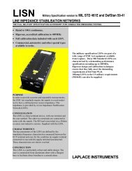
L-<strong>Band</strong> J <strong>Series</strong> CMPA (<strong>VZL</strong>-<strong>6943J2</strong>) 04/00 TD-78 16Figure 3. Small Signal Gain
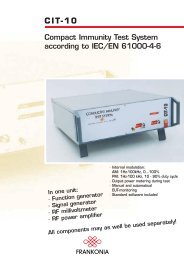
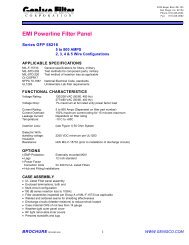
L-<strong>Band</strong> J <strong>Series</strong> CMPA (<strong>VZL</strong>-<strong>6943J2</strong>) 04/00 TD-78 17Figure 4. Residual AM 0 kHz to 10 kHz
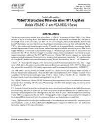
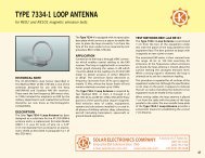
L-<strong>Band</strong> J <strong>Series</strong> CMPA (<strong>VZL</strong>-<strong>6943J2</strong>) 04/00 TD-78 18Figure 5. Residual AM 10 kHz to 50 kHz
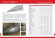
L-<strong>Band</strong> J <strong>Series</strong> CMPA (<strong>VZL</strong>-<strong>6943J2</strong>) 04/00 TD-78 19Figure 6. Residual AM 50 kHz to 100 kHz
SUPPORT SERVICESDocumentationCPI Satcom Division provides a commercial documentationpackage for all products. The content of thispackage is determined by the nature of the productconcerned, and the quantity is governed by contractualrequirements. The standard package for Satcompower amplifiers includes a comprehensive Operationand Maintenance Manual, outline and interface drawings,Manufacturing Test Report and spare parts lists.Outline and interface drawings provide dimensions andthe location and size of mounting holes, duct work, andwaveguide, so that site preparations can be accomplishedprior to receipt of the equipment.The Service Manual provides instruction for unpackingand installation, initial set-up, calibration, normal operation,maintenance and repair of the equipment. Themanual includes schematic diagrams, block diagrams,and wiring information sufficient for use by maintenancepersonnel.The Acceptance Test Report outlines the test performedlimits established. Space is provided on thetest report for recording and certifying the test results,consolidating all related information in one document.The spare parts documentation consists of a recommendedspare parts list to support the equipment for aone-to-two year period of operation. A CSI AcceptanceTest can be performed at customer’s optionwhich will repeat and verify results of selected performancetests that were already recorded in the standardacceptance test.Small training groups (up to five students) assure thecustomer that each student has an opportunity to participatefully in demonstration activities. Courses maybe conducted at the CPI factory or on-site. Courseduration varies from several days to one or two weeks,depending on the scope of work agreed upon and theskill level of the students.Field ServiceThe product support activity of CPI includes a staff ofexperienced, professional service technicians to assistusers in maintaining full performance from their CPIpower amplifiers. A telephone “hot line” permits accessto one of these technicians on a 24-hour per daybasis. Operational problems often can be diagnosed,corrective action prescribed, and normal operationrestored through such telephone consultation. Whencalled for, however, the service technicians are preparedto give on-site assistance.Product Support carries an large inventory of spareparts that can be made ready for shipment within 24hours. Coupled with a dedicated dial-in telephone line,this service is effective in aiding users to restore equipmentto operational status with minimum downtime.Technical assistance and factory approved replacementparts are also available at strategically locatedRegional Service Centers in the U.S.A., Europe andthe Pacific Rim.TrainingCPI Satcom Division is prepared to conduct trainingcourses covering the installation, operation and maintenanceof its equipment. The training course on highpower amplifiers consists of lectures using training material,such as technical manuals and drawings, plusactual operation and adjustments demonstrated on theequipment.L-<strong>Band</strong> J <strong>Series</strong> CMPA (<strong>VZL</strong>-<strong>6943J2</strong>) 04/00 TD-78 20