Facility Audit: Deer Park, TX - Clean Harbors
Facility Audit: Deer Park, TX - Clean Harbors
Facility Audit: Deer Park, TX - Clean Harbors

Create successful ePaper yourself
Turn your PDF publications into a flip-book with our unique Google optimized e-Paper software.
<strong>Facility</strong> <strong>Audit</strong>: <strong>Deer</strong> <strong>Park</strong>, <strong>TX</strong><br />
1
Table of Contents<br />
1.0 General Company Information ......................................................................................................................... 1<br />
Introduction......................................................................................................................................................... 1<br />
Network of Services............................................................................................................................................ 1<br />
2.0 <strong>Facility</strong> Information .......................................................................................................................................... 3<br />
<strong>Facility</strong> Overview................................................................................................................................................ 3<br />
<strong>Facility</strong> Site Plan................................................................................................................................................. 5<br />
<strong>Facility</strong> History ................................................................................................................................................... 6<br />
Site Characterization........................................................................................................................................... 6<br />
Security ............................................................................................................................................................... 7<br />
Directions to <strong>Facility</strong>........................................................................................................................................... 7<br />
3.0 Operating Licenses and Permits........................................................................................................................ 9<br />
Permit Summary ................................................................................................................................................. 9<br />
Principal Operating Licenses/Permits................................................................................................................. 9<br />
Principal Contacts/Agencies ............................................................................................................................. 10<br />
4.0 Process Description......................................................................................................................................... 12<br />
Incineration ....................................................................................................................................................... 12<br />
Tank Storage ..................................................................................................................................................... 17<br />
Container Storage.............................................................................................................................................. 22<br />
Miscellaneous Units.......................................................................................................................................... 25<br />
Landfill.............................................................................................................................................................. 29<br />
Waste Acceptance............................................................................................................................................. 32<br />
Analytical Laboratory ....................................................................................................................................... 33<br />
Geology and Groundwater................................................................................................................................ 35<br />
5.0 Closure Plan.................................................................................................................................................... 40<br />
6.0 Insurance......................................................................................................................................................... 40<br />
7.0 Financial Information...................................................................................................................................... 41<br />
8.0 Appendix......................................................................................................................................................... 41<br />
2
1.0 General Company Information<br />
Introduction<br />
<strong>Clean</strong> <strong>Harbors</strong> is a publicly traded company that maintains a vast network of service centers<br />
waste management, and treatment and disposal facilities, and provides a broad range of<br />
environmental services. Services include hazardous and non-hazardous waste transportation and<br />
disposal, laboratory chemical packing, emergency response, field services and industrial<br />
maintenance. Since its inception in 1980, <strong>Clean</strong> <strong>Harbors</strong> has grown to become the largest<br />
provider of environmental services in the North America. Its locations span the United States,<br />
Canada, Mexico, and Puerto Rico.<br />
Network of Services<br />
Strategically located across North America, <strong>Clean</strong> <strong>Harbors</strong>’ service centers are the primary<br />
interface with customers and the focal point for providing waste management activities,<br />
laboratory chemical packing services, emergency response, field services and industrial<br />
maintenance. From the service center site service crews and equipment are dispatched to<br />
perform various planned work on customer sites, as well as emergency response. <strong>Clean</strong>Pack<br />
teams are also based at the service centers and provide customers with laboratory chemical<br />
packing services.<br />
Technical Services - Transportation & Disposal - <strong>Clean</strong> <strong>Harbors</strong>’ network of company owned<br />
waste treatment, storage and disposal facilities are located across North America and offer a<br />
broad range of disposal, recycling and treatment technologies for hazardous and non-hazardous<br />
materials. Technologies include:<br />
• Incineration<br />
• Wastewater Treatment<br />
• Recycling<br />
• Fuels Blending<br />
• Landfill<br />
All of our disposal facilities uphold rigorous quality assurance programs to meet the highest<br />
standards of both internal and external audits.<br />
Waste streams handled by <strong>Clean</strong> <strong>Harbors</strong> can be in any form from gas to liquids, solids and<br />
sludge. <strong>Clean</strong> <strong>Harbors</strong> can dispose of virtually any type of waste, hazardous, or non-hazardous<br />
from exotic water reactive wastes to typical paint or oil wastes.<br />
Our transportation services handle everything from small one-time shipments to multiple large<br />
shipments, and include drum, bulk and rail capabilities. Once you place your order and before<br />
the pick up is even made, <strong>Clean</strong> <strong>Harbors</strong> begins the process of managing your waste. Your order<br />
enters our Logistics center where your waste is designated for disposal via the least cost routing.<br />
Company owned and operated trucks are assigned based on the most efficient route or on pre-<br />
1
established schedules. Satellite tracking and communication allows trucks to be dispatched on<br />
the fly from anywhere in the country. The disposal facility is determined based on the most<br />
appropriate, yet lowest cost disposal method.<br />
Plant inventories are centrally monitored real-time. Our facilities know in advance and begin<br />
load planning for efficient processing of incoming waste. All this upfront work is managed<br />
centrally and electronically to provide the most cost effective and efficient handling of orders<br />
and waste transportation and disposal in the industry.<br />
<strong>Clean</strong>Pack® Laboratory Chemical Packing Services - <strong>Clean</strong> <strong>Harbors</strong>’ staff of professionally<br />
trained <strong>Clean</strong>Pack chemists work on customer sites to collect, label and package unwanted<br />
laboratory quantities of chemicals and wastes for disposal in compliance with local, state, and<br />
federal regulations. <strong>Clean</strong>Pack teams provide reactive material handling services for the proper<br />
management and disposal of highly reactive and dangerous chemicals, laboratory move services<br />
and facility closures. Our household hazardous waste collection program offers a cost effective<br />
and safe manner for states, cities and towns to keep their residents free of unwanted old and<br />
obsolete pesticides, paints, fertilizers and other potentially harmful materials.<br />
Site Services - Field Service crews work in hazardous and non-hazardous environments. Crews<br />
perform routine planned jobs and emergency responses specializing in site decontamination,<br />
biohazard response, confined space entry, product recovery and transfer, excavation and<br />
removal, vacuum services, as scarifying and sandblasting, marine services and booming.<br />
Remediation and environmental construction services of any scale including remedial systems<br />
design, custom fabrication and welding, mobile treatment, well maintenance and video<br />
inspection, complement <strong>Clean</strong> <strong>Harbors</strong>’ capabilities.<br />
Industrial Service teams use advanced industrial cleaning technologies including chemical<br />
cleaning, hydroblasting, vacuum services, steam cleaning, sodium bicarbonate blasting, and<br />
abrasive blasting to accomplish fast turnaround during time-critical plant shutdowns.<br />
2
2.0 <strong>Facility</strong> Information<br />
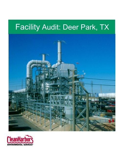
<strong>Facility</strong> Overview<br />
<strong>Clean</strong> <strong>Harbors</strong> <strong>Deer</strong> <strong>Park</strong> operates two (2) commercial hazardous waste incinerator trains at its<br />
<strong>Deer</strong> <strong>Park</strong>, Texas facility. Incineration Train I consists of a 3.6-meter rotary kiln, a Loddby<br />
Liquids injection burner, a horizontal afterburner, a wet scrubber system, and associated waste<br />
feed and emission control systems.<br />
The Train I Incineration System is designed, permitted and operated to burn hazardous and nonhazardous<br />
wastes, primarily industrial wastes regulated under RCRA and TSCA (PCB wastes)<br />
standards. The system has been tested to meet a Destruction and Removal Efficiency (DRE) of<br />
99.99% for RCRA hazardous wastes and 99.9999% for PCB wastes. The Train I unit has a highenergy<br />
impact Venturi type wet scrubbing system, two Wet Electrostatic Precipitators and a<br />
Selective Catalytic Reduction unit.<br />
Incineration Train II consists of a 4.4-meter rotary kiln, a mechanical fluidized bed reactor<br />
(Rotary Reactor), a common vertical afterburner, a wet scrubber system, and associated waste<br />
feed and emission control systems.<br />
The Train II incineration unit are designed, permitted and operated to burn hazardous (RCRA)<br />
and non-hazardous industrial wastes per all applicable regulations and performance standards.<br />
The unit has been tested to meet a Destruction and Removal Efficiency (DRE) of 99.99% for<br />
RCRA hazardous wastes. The Train II unit has a high-energy impact Venturi type wet scrubbing<br />
system, two Wet Electrostatic Precipitators and a Selective Catalytic Reduction unit.<br />
Incineration residues generated from the Train I and II incinerators is analyzed to ensure<br />
compliance with all applicable Land Disposal Restrictions. Incineration residues are established<br />
and encapsulated as necessary to meet these rules. All residues are land-disposed in on-site<br />
landfill units.<br />
3
<strong>Facility</strong> Name<br />
Location<br />
County<br />
<strong>Facility</strong> Owner<br />
Property Owner<br />
<strong>Clean</strong> <strong>Harbors</strong> <strong>Deer</strong> <strong>Park</strong>, LP<br />
2027 Independence <strong>Park</strong>way South<br />
La Porte, <strong>TX</strong> 77571<br />
Harris<br />
<strong>Clean</strong> <strong>Harbors</strong> <strong>Deer</strong> <strong>Park</strong>, LP<br />
2027 Independence <strong>Park</strong>way South<br />
La Porte, <strong>TX</strong> 77571<br />
<strong>Clean</strong> <strong>Harbors</strong> Environmental Services, Inc.<br />
<strong>Facility</strong> I.D. No 50089<br />
Permits Type<br />
Waste, Air, Water and PCB’s<br />
Waste Description<br />
Incineration<br />
Services Provided<br />
Waste Incineration<br />
4
<strong>Facility</strong> Site Plan<br />
5
<strong>Facility</strong> History<br />
Year Event<br />
1969 Land purchased<br />
1971 Installation of 2.8 meter (diameter) rotary kiln<br />
1974 Landfill operation (South)<br />
1980 Installation of PCB Shredder System<br />
1981 Received TSCA Letter of Authorization (First in USA)<br />
1985 Installation of 3.6 meter slagging rotary kiln (replacing 2.8 m kiln)<br />
1988 Received RCRA Part B Permit (First in USA)<br />
1988 Installation of 4.4 meter slagging rotary kiln<br />
1989 Installation of Rotary Reactor (bulk solids burner)<br />
1989 Installation of shredder on front wall of 4.4 meter kiln<br />
1990 MTR landfill operation (North)<br />
1991 Installation of glove boxes for cylinder gas disposal and drum liquid aspiration<br />
1993 Stabilization & Encapsulation <strong>Facility</strong> on-line<br />
1994 MTR landfill permitted (East)<br />
1994 Industry of the Year - <strong>Deer</strong> <strong>Park</strong> Chamber of Commerce<br />
1995 Awarded E.I. Digest for no Notice of Violations for the year<br />
1996 Closure of South Landfill certified by TCEQ<br />
1997 Merger with Laidlaw Environmental Services, Inc.<br />
1998 Merger with Safety-Kleen<br />
2002 Acquired by <strong>Clean</strong> <strong>Harbors</strong><br />
2004 Installed WESP’s for MACT compliance<br />
2005 Development of the Comprehensive Performance Test (CPT)<br />
2006 CPT was performed and submitted for Train I<br />
2007 TCEQ request to lower the pressure drop and the water flow rates for Train I<br />
USEPA request to lower the PCB operating temperature for Train I<br />
East Landfill permit issued in June<br />
2008 TCEQ/USEPA issued a MACT Finding of Compliance for Train I<br />
East Landfill Operation began in February<br />
Dioxin/Furan testing performed on Train II<br />
Expect Class 3 Permit Modification to lower RCRA operating conditions on<br />
Trains I and II<br />
Site Characterization<br />
<strong>Clean</strong> <strong>Harbors</strong>’ facility in <strong>Deer</strong> <strong>Park</strong>, Texas, delivers state-of-the-future technological solutions<br />
for companies seeking the safest, responsible incineration of hazardous waste. With an<br />
unparalleled commitment to customer value, convenience and satisfaction, <strong>Deer</strong> <strong>Park</strong> maximizes<br />
security and minimizes risk for large and small generators.<br />
6
Security<br />
Access into the facility is controlled by security personnel. Visitors are required to sign in with<br />
the guard and at the Administration Building, view a Safety Orientation Video, and are issued a<br />
visitor badge. The facility’s perimeter is totally fenced with hurricane fencing utilizing threestrand<br />
barbed wire. Appropriate notices are posted around the perimeter.<br />
Directions to <strong>Facility</strong><br />
2027 Independence <strong>Park</strong>way South<br />
La Porte, <strong>TX</strong> 77571<br />
From Houston-Hobby Airport<br />
Take I-45 North to Loop 610.<br />
Take Loop 610 East to Hwy 225 East (Pasadena/LaPorte Hwy) - (Approximately 1-1½ miles<br />
from I-45/Loop 610 Intersection)<br />
Take Hwy 225 East approximately 9-10 miles (past Shell refinery/chemical complex).<br />
Exit Independence <strong>Park</strong>way South, cross over Hwy 225 (left), traveling North on Independence<br />
<strong>Park</strong>way South.<br />
Travel approximately 1-1 ½ miles North.<br />
Note: You will pass the <strong>Clean</strong> <strong>Harbors</strong> Purchasing building. This is not the facility entrance;<br />
travel a little further.<br />
<strong>Facility</strong> entrance is located on the left (west side) situated between tank batteries of<br />
Intercontinental Terminals (ITC).<br />
<strong>Facility</strong> sign "<strong>Clean</strong> <strong>Harbors</strong>."<br />
Proceed through ITC gate, over the railroad tracks, to the <strong>Clean</strong> <strong>Harbors</strong> guard gate entrance<br />
(follow signs for Visitors and Employees), check in, then proceed to Administration Building<br />
and check in with the receptionist.<br />
7
From George Bush International Airport (IAH)<br />
Exit Airport to Hwy 59.<br />
Take Hwy 59 South to Beltway 8 (Sam Houston Tollway).<br />
Take Beltway 8 East (Approximately 15-19 miles).<br />
Continue on Beltway 8 over the Houston Ship Channel Bridge (toll fee $2.00) and continue to<br />
Hwy 225.<br />
Take Hwy 225 East (turn left) approximately 2-3 miles (past Shell Refinery/Chemical Complex).<br />
Exit Independence <strong>Park</strong>way South, cross over Hwy 225 (left), traveling North on Independence<br />
<strong>Park</strong>way South.<br />
Travel approximately 1-1 ½ miles North.<br />
Note: You will pass the <strong>Clean</strong> <strong>Harbors</strong> Purchasing building. This is not the facility entrance;<br />
travel a little further.<br />
<strong>Facility</strong> entrance is located on the left (west side) situated between tank batteries of<br />
Intercontinental Terminals (ITC).<br />
<strong>Facility</strong> sign "<strong>Clean</strong> <strong>Harbors</strong>".<br />
Proceed through ITC gate, over the railroad tracks, to the <strong>Clean</strong> <strong>Harbors</strong> guard gate entrance<br />
(follow signs for Visitors and Employees), check in, then proceed to Administration Building<br />
and check in with the receptionist.<br />
8
3.0 Operating Licenses and Permits<br />
Permit Summary<br />
<strong>Clean</strong> <strong>Harbors</strong> of <strong>Deer</strong> <strong>Park</strong>, LP is currently permitted by the Texas Commission on<br />
Environmental Quality (TCEQ) for the storage and disposal of hazardous and non-hazardous<br />
waste, as well as associated air, water and related activities. Additionally the facility is<br />
authorized to store and dispose of TSCA regulated PCB’s by the U.S. Environmental Protection<br />
Agency.<br />
Permit Type/Governing Agency Permit No. Expiration Date<br />
RCRA Part B<br />
TCEQ - Austin<br />
50089 01/18/15<br />
NSR Air Permit<br />
TCEQ – Region 12<br />
5064 09/05/10<br />
Title V Permit<br />
TCEQ - Austin<br />
O-01566 10/25/06***<br />
TPDES Permit*<br />
TCEQ – Austin<br />
01429 04/01/99*<br />
NPDES Permit**<br />
TCEQ - Austin<br />
<strong>TX</strong>0005941 11/18/90**<br />
TSCA Authorization***<br />
EPA – Region IV<br />
N/A 08/05/02***<br />
*The permit renewal will be withdrawn simultaneously with submittal of a permit renewal with<br />
modification.<br />
**USEPA-Region VI has transferred the permit to the TCEQ for consolidation into TPDES<br />
permit.<br />
***Permit remains in force awaiting approval of renewal application.<br />
Principal Operating Licenses/Permits<br />
Copies of existing permits which detail types of waste management licensed capacities and waste<br />
types accepted are available for inspection upon request at the site. Selected permit pages may<br />
be attached at the end of this audit under Appendix 8.0.<br />
9
Principal Contacts/Agencies<br />
The list of contacts below can provide additional information regarding <strong>Clean</strong> <strong>Harbors</strong> of <strong>Deer</strong><br />
<strong>Park</strong>’s facility or operations or compliance.<br />
Operations<br />
Regulatory<br />
RCRA Permit<br />
Engineer<br />
New Source Review<br />
Permit Engineer<br />
Title V Operating<br />
Permit Engineer<br />
TPDES Permit<br />
RCRA Inspector<br />
Air Inspector<br />
Wastewater Inspector<br />
Dennis Wainwright, General Manager<br />
<strong>Clean</strong> <strong>Harbors</strong> <strong>Deer</strong> <strong>Park</strong>, LP<br />
Independence <strong>Park</strong>way South<br />
La Porte, <strong>TX</strong> 77571<br />
(281) 930-2411<br />
Kevin Honohan<br />
Senior Compliance Manager<br />
<strong>Clean</strong> <strong>Harbors</strong> <strong>Deer</strong> <strong>Park</strong>, LP<br />
Independence <strong>Park</strong>way South<br />
La Porte, <strong>TX</strong> 77571<br />
(281) 930-2482<br />
Mr. Vahab Haghighatian<br />
TCEQ - Austin<br />
(512) 239-6081<br />
Mr. Joseph Marini<br />
TCEQ - Austin<br />
(512) 239-1377<br />
Mr. Tom Ennis<br />
TCEQ - Austin<br />
(512) 239-3553<br />
Mr. Kelly Holligan<br />
TCEQ - Austin<br />
(512) 239-2369<br />
Mr. John Wilson<br />
TCEQ – Region 12<br />
(713) 767-3743<br />
Ms. Carolyn Guillory<br />
TCEQ – Region 12<br />
(713) 767-3600<br />
Ms. Jeannette Mock<br />
TCEQ – Region 12<br />
(713) 767-3600<br />
10
Groundwater Inspector<br />
TSCA Authorization<br />
TSCA Inspector<br />
Pollution<br />
Mr. Charlie Burner<br />
TCEQ – Region 12<br />
(713) 767-3616<br />
Mr. Jim Sales<br />
EPA – Region VI<br />
(214) 665-6796<br />
Mr. Ken Ofunrein<br />
Texas Department of Health - Austin<br />
(512) 834-6600 x2430<br />
Mr. Robert Allen<br />
Acting Director<br />
Harris County Pollution Control<br />
Pasadena, <strong>TX</strong><br />
(713) 920-2831<br />
11
4.0 Process Description<br />
Incineration<br />
<strong>Deer</strong> <strong>Park</strong> utilizes state-of-the-art thermal treatment (incineration) technologies along with air<br />
pollution control technology to treat thousands of tons of liquid, solid and gaseous hazardous<br />
wastes annually. Wastes are incinerated in an oxidized atmosphere at temperatures high enough<br />
to achieve required destruction.<br />
The incineration system consists of two incineration Train units. Train I has a permitted thermal<br />
capacity of 180 MM BTU/hr and includes a 3.6 meter diameter slagging rotary kiln, Loddby<br />
liquids burner and a horizontal afterburner. Train II has a permitted thermal capacity of 213.5<br />
MM BTU/hr and includes a 4.4 meter diameter slagging rotary kiln, the Rotary Reactor (RR), a<br />
vertical afterburner and four (4) McGill liquid burners. Abatement hardware utilized for<br />
emission control per Train incorporates a saturator, two parallel condensers, a collision scrubber<br />
(Calvert) and a Chevron mist eliminator.<br />
In addition to the above, each incineration train has two wet electrostatic precipitator (WESP)<br />
systems for removal of sub-micron particulate (including heavy metals) and two selective<br />
catalytic reduction (SCR) systems for the removal of NOx emissions.<br />
Particulate matter is removed from the gas stream in each WESP by imparting a positive charge<br />
on the particles in an electric field, and then collecting the positively charged particulate on a<br />
grounded (negatively-charged) collection surface. A continuous spray of fresh water is injected<br />
into the WESP to provide a conductive liquid film covering on the non-conductive plastic<br />
collection tubes. The charged particles are collected in the conductive liquid film; this will<br />
prevent build-up of particles on the collection tube surface. A periodic water flush cleans the<br />
tubes. The water discharged from the WESP vessels in a blow-down tank and recycled or<br />
discharged to the wastewater treatment plant.<br />
Two 1,350 horsepower fans are also part of this system. They accommodate the system static<br />
pressure introduced by the gas cleaning equipment (two new WESP vessels in series and one<br />
SCR system per train) and ductwork. Fan inlet dampers are provided, in addition to the fan, to<br />
accommodate the wide-ranging flow and pressure conditions.<br />
The SCR equipment is installed downstream of the fan on each gas cleaning train and operated<br />
under positive pressure. The SCR system requires heating the flue gas to the 525 – 600º F range<br />
and then injecting ammonia (NH3) as ammonium hydroxide (NH4OH; aqueous ammonia). The<br />
NH3 flue gas is then thoroughly mixed via a static mixer prior to it passing through a catalyst<br />
bed, where NOx is converted into nitrogen and water vapor.<br />
Two separate individual stacks are downstream of the SCR equipment for discharging the clean<br />
flue gas to atmosphere.<br />
12
A. Process Flow Diagrams<br />
13
TRAIN I – 3.6 METER KILN FLOW DIAGRAM & TRAIN II METER and ROTARY<br />
FLOW DIAGRAM<br />
14
B. Waste Feeds<br />
Waste port assignment into incineration hardware is determined prior to waste receipt. This<br />
waste port assignment is determined upon careful review of the stream by Waste Acceptance<br />
Chemists (WACs). Factors such as physical form, chemical make-up, concentration of<br />
compounds/metals, health/safety and permit compliance information enable the WACs to<br />
determine the safest and most efficient method of feed entry into the system.<br />
C. Gas Quenching System<br />
The gas quenching systems of the two Trains are essentially the same. In each Train, the<br />
combustion product gases are typically exposed to temperatures of at least 1800 o F for a<br />
o<br />
minimum of two seconds. Normal operating conditions provide for a final temperature of 2200<br />
F. The off-gases flow into the saturator, which is a refractory lined quench tower with a<br />
pressurized water spray, where they are cooled to approximately 180 o F. The gases then pass<br />
into twin packed-bed condensers, where they impinge on tellerettes while being scrubbed by a<br />
countercurrent water spray. The gases pass into a collision Calvert scrubber, then into a set of<br />
demisters, and finally through an induced draft fan and out a common stack. The condensers, the<br />
scrubbers and connecting ductwork are constructed of fiberglass.<br />
D. Ash Collection<br />
Incinerated solids/slag are collected in twenty (20) cubic yard roll-off bins under a discharge unit<br />
from the rotary kilns and the rotary reactor. Approximately every hour the ash collected is<br />
manually leveled in the bin to ensure even fill. A typical plant output of ash is about 6 to 7<br />
twenty cubic yard bins per day.<br />
E. Ash Tracking Prior to Landfill Deposition<br />
Each collection bin is numbered and referenced. During the incineration process and the filling<br />
of a specific bin, waste stream numbers are tracked via barcode readings and manual entries. The<br />
ash generated is tracked. From this process, EPA waste codes can be managed from a point of<br />
analytical testing. Organic screening procedures are performed on each bin and metals (TCLP)<br />
on each batch of stabilized ash to ensure all applicable land disposal restrictions are met prior to<br />
landfill deposition.<br />
16
Tank Storage<br />
All waste storage tanks at <strong>Deer</strong> <strong>Park</strong> are aboveground except for the following:<br />
Tank #<br />
T-1202<br />
T-1203<br />
T-1204<br />
T-1001-1<br />
T-1001-2<br />
T-1001-3<br />
T-638<br />
T-20 -1<br />
Description<br />
S&E facility - each is a 125 yd 3 steel-lined pit used to receive bulk solids<br />
material for processing<br />
S&E facility - a 350 yd 3 concrete pit into which stabilized material is<br />
discharged from the pugmill.<br />
Mix Building - each is a 75 yd 3 steel-lined concrete pit used for material<br />
processing (e.g., repacking of bulk solids into drums).<br />
A 7,575-gallon steel-lined pit. Located in the Rotary Reactor feed tower<br />
and used for receipt of bulk material to be clamshell fed to the Rotary<br />
Reactor.<br />
Train I Bulk Feed Tank. A 7,198 gallon in-ground tank used to feed<br />
solids via clamshell bucket to the 3.6 meter kiln.<br />
Each of the above tanks meets all the requirements for leak detection. Tanks T-1001-1, 2, 3 are<br />
located in the Mix Building, which incorporates basement access for inspections. Each of the<br />
other tanks has a leak detection system as required by 40 CFR 264.193.<br />
<strong>Deer</strong> <strong>Park</strong> conducts rigorous annual inspections on all tanks to monitor construction integrity.<br />
All <strong>Deer</strong> <strong>Park</strong> piping that is used for the transport of waste is above ground except for several<br />
portions of our on-site landfill leachate piping. <strong>Clean</strong> <strong>Harbors</strong> <strong>Deer</strong> <strong>Park</strong> transports on-site<br />
landfill generated leachate via piping from our landfill area to tankage in our process area.<br />
Several sections of this piping are routed underground in order to cross in-plant roadways. Each<br />
of these underground sections is encased in a separate pipe to provide secondary containment.<br />
<strong>Deer</strong> <strong>Park</strong> conducts a rigorous program of fugitive emissions monitoring and repair, consistent<br />
with TCEQ 28 MID, which is equivalent with MACT standards (i.e. quarterly monitoring, 500<br />
ppm leak rate, directed maintenance, etc.).<br />
17
TABLE II SECONDARY CONTAINMENT DATA<br />
CONTAINMENT AREA<br />
APPROXIMATE<br />
CONTAINMENT<br />
LARGEST<br />
25 YR-24 HR<br />
DIMENSIONS<br />
VOLUME<br />
TANK (gals)<br />
RAINFALL (gals) (10.5")<br />
NORTH TANK FARM 2.25' x 115' x 277' 418,721 200,000 219,900<br />
WEST TANK FARM 5' x 50'x 67' 27,590 7,000 21,900<br />
S & E T1202 - T1203 1 29.2' x 19.5' x 5.9' 25,312 25,312 0 2<br />
S & E V1204 Irregular 2088 ft 2 x 2' 31,236 13,500 1,316<br />
MIX BLDG 16' x 44' x 60.5' 329,400 202,500 0 2<br />
1<br />
Double-walled tanks<br />
2<br />
Covered area<br />
21
Container Storage<br />
<strong>Clean</strong> <strong>Harbors</strong> <strong>Deer</strong> <strong>Park</strong> has a number of hazardous waste container storage areas authorized<br />
under its current permit.<br />
The permitted storage areas are:<br />
• Drum Storage Pad 1 (DSP-1)<br />
• Drum Storage Pad 2 (DSP-2)<br />
• Drum Storage Pad 3 (DSP-3)<br />
• Drum Storage Pad 4 (DSP-4)<br />
• Drum Storage Pad 5 (DSP-5)<br />
• Drum Storage Pad 6 (DSP-6)<br />
• Drum Storage Pad 7 (DSP-7)<br />
• Drum Storage Pad 8 (DSP –8)<br />
• Warehouse<br />
• Transformer and Drum Handling Building<br />
• Container Storage Warehouse<br />
• Bin Storage Area 1 (BSA-1)<br />
• Bin Storage Area 2 (BSA-2)<br />
• Bin Storage Area 3 (BSA-3)<br />
• Front-Line Storage Pad<br />
• Waste Receiving Pad<br />
Table III provides data for each permitted storage area (NOR number, waste types, rated<br />
capacity, dimensions, stacking height, aisle spacing, containment volume, ignitable, reactive or<br />
incompatible wastes).<br />
Container storage areas are used to receive, count, sample, verify, stage, and store hazardous<br />
wastes prior to, during and after processing. Hazardous waste containers are kept tightly sealed<br />
except when necessary for sampling or processing. The containers used for managing wastes in<br />
these areas are pails, drums, cylinders, boxes, tote bins, roll-off bins, and tank trailers (all DOT<br />
approved for hazardous waste). Each storage area has a specified capacity that is not exceeded.<br />
All hazardous waste container storage areas are physically located at least 50 feet from the<br />
nearest property boundary line and appropriate distances from other units based upon fire safety<br />
requirements.<br />
Drum stacking heights are maintained to minimize possible spills and fire hazards. Drum aisle<br />
spacing requirements are maintained to minimize fire hazards and permit access to each drum for<br />
22
outine inspections as well as emergency response. Table V.B. details specific stacking heights<br />
and aisle spacing for each hazardous waste container storage area.<br />
All hazardous waste container storage areas have integral impervious secondary containment.<br />
The secondary containment is designed to hold at least 10% of the capacity of the storage area,<br />
or the volume of the largest single hazardous waste container (whichever is larger). The<br />
secondary containment is also sized to contain the volume of a 25 year,24 hour rainfall (10.5<br />
inches), or is designed to prevent rain infiltration Table III provides specific dimensions and<br />
capacities for each secondary containment area.<br />
The facility Standard Work Practices (SWPs), operator training, equipment design, process<br />
safety program, and emergency response procedures and equipment allow the site to safely store<br />
potentially ignitable, reactive or incompatible wastes.<br />
23
Miscellaneous Units<br />
The <strong>Clean</strong> <strong>Harbors</strong> <strong>Deer</strong> <strong>Park</strong> facility manages hazardous waste in six miscellaneous units, three<br />
of which are authorized under the current permit, the other being a unit for which authorization is<br />
being requested.<br />
These six units are:<br />
• Railcar Unloading Area<br />
• Direct Burn Areas<br />
• Container QC Area<br />
• Continuous Mixer/B-1203 Pugmill (S & E <strong>Facility</strong>)<br />
• Rotary Reactor Feed System<br />
• PCB Shredder<br />
The first three of these units were permitted as Miscellaneous Units per a previous agreed order<br />
between the company and the Texas Water Commission. The fourth unit (the Continuous<br />
Mixer/B-1203 Pugmill) was permitted as a Miscellaneous Unit prior to construction, based upon<br />
its process function.<br />
Table IV summarizes Miscellaneous Unit data, according to Notice of Registration (NOR) Unit<br />
Number, storage or process function, waste managed in each unit, rated capacity, dimensions,<br />
and whether the unit processes or stores ignitable or incompatible wastes.<br />
A. Railcar Unloading Area<br />
The railcar unloading area is designed to accommodate two 25,000-gallon bulk liquid (or sludge)<br />
railcars during unloading operations. The combined capacity of the system at any one time is<br />
50,000 gallons (two railcars). During unloading, both railcars may be simultaneously processed.<br />
Unloaded waste material may be pumped to the adjacent tank farm or directly to the incinerators.<br />
The area is constructed of a reinforced concrete slab surrounded by a 6-inch concrete curb. A<br />
drainage trench runs through the area, and is sloped to a collection sump equipped with an<br />
automatic pump. The capacity of the drainage sump is 2,336 gallons. A level switch<br />
automatically activates the pump so that collected material can be removed immediately. This<br />
allows sufficient volume to manage rainfall. The railcar unloading area is equipped with a<br />
dedicated vent system to control emissions.<br />
25
B. Direct Burn Areas<br />
<strong>Clean</strong> <strong>Harbors</strong> <strong>Deer</strong> <strong>Park</strong> facility processes many bulk waste streams by feeding directly to an<br />
incinerator system. In many instances, this is the safest and most environmentally responsible<br />
method for processing incompatible or reactive wastes. These materials are not transferred from<br />
their original trailers or container, or blended with any other waste materials.<br />
There are three separate direct burn areas to service the facility's incinerator systems. These<br />
areas are identified as:<br />
• Rotary Reactor Direct Burn Area<br />
• 4.4 Meter Kiln Direct Burn Area<br />
• Afterburner/Loddby Direct Burn Area - (The Afterburner/Loddby Direct Burn Area is<br />
divided into two parts: the Scale Section and the 29 Pad Section).<br />
The combined capacity of the Direct Burn Areas is eight 5,500-gallon trucks (44,000 gallons).<br />
Each of the areas is located on a paved area that has curbing or sloped drainage to provide for the<br />
containment of spills and/or contaminated rainwater. To control emissions, trailers processed at<br />
the Direct Burn Areas are connected to a dedicated vent system that feeds directly to the<br />
incinerator systems.<br />
C. Container QC Area<br />
The Container QC area is located due west of DSP-3 and DSP-6. It is a long, narrow area that is<br />
used for sampling and storage of containers that have not achieved Waste Analysis Plan<br />
discharge from the laboratory. Upon achievement of laboratory discharge, within 24 hours the<br />
containers in this area are moved to other permitted storage or processing units. Maximum<br />
storage capacity for the units is 75,000 gallons. The unit has secondary containment that meets<br />
the requirements of a Container Storage Area.<br />
D. Continuous Mixer (Pugmill B-1203)<br />
The Continuous Mixer (Pugmill B-1203) is an intensively agitated mixer installed and used in<br />
the waste Stabilization and Encapsulation (S&E) process prior to landfill. The pugmill receives<br />
screened or shredded waste, stabilizing agents, water and slurries. In the pugmill, the materials<br />
are thoroughly mixed and discharged to the T-1204 pit for storage prior to disposal in the<br />
landfill.<br />
The pugmill is electrically powered and has a capacity of 22 cubic yards. No ignitable, reactive,<br />
or incompatible wastes are processed in the pugmill. The mixing operation is controlled by<br />
process computer and is monitored by on-site operators to prevent overfilling and to ensure the<br />
design operational efficiency.<br />
26
The pugmill is completely enclosed inside the S & E building, which provides containment and<br />
protection from direct precipitation and run-on. The building ventilation and baghouse filter<br />
system also provides dust emission control for the pugmill.<br />
E. Rotary Reactor Feed System<br />
The Rotary Reactor Feed System consists of the Rotary Reactor Feed Tank (T-638), Rotary<br />
Reactor Shredder and the Rotary Reactor Feed Building. The Rotary Reactor Feed Tank is used<br />
to store bulk solids for feed to the Rotary Reactor Kiln and the Rotary Reactor Feed Building<br />
houses the clamshell bucket that conveys the waste T-638 to the Rotary Reactor Kiln. Tank T-<br />
638 is 12 feet x 9 feet x 9.5 feet with a total capacity of 37.5 cubic yards. The feed building is<br />
20,900 cubic feet in volume.<br />
The Rotary Reactor Feed Tank is an open-topped, double-walled, below-grade steel tank that is<br />
completely enclosed below grade in a concrete vessel with a leak detection sump. The doublewalled<br />
construction provides an adequate secondary containment system.<br />
The Rotary Reactor Feed Tank is filled from bin trucks or a front-end loader with an operator in<br />
attendance. This ensures that the tank will not be over-filled. Material placed into this tank is<br />
promptly moved to the Rotary Reactor Shredder via the clamshell bucket system. The feed<br />
material contains no free liquids, and incompatible materials are not fed to this tank. If ignitable<br />
wastes are added to this unit, procedures for ignitable tanks waste are followed.<br />
The Rotary Reactor Feed Tank and the clamshell bucket are completely enclosed in the Rotary<br />
Reactor Feed Building. The building has a dedicated vent system that feeds to the incinerators to<br />
control emissions. The building also protects the feed system from direct precipitation, run-on<br />
and wind action. The Rotary Reactor Feed Tank (Tank T-638) is inspected, tested and certified<br />
for hazardous waste service as part of the facility’s annual waste tank integrity inspection.<br />
F. PCB Shredder<br />
The PCB Shredder is a device that is used to shred containers of PCB-contaminated materials. It<br />
is often necessary to cut up some PCB-contaminated containers and materials to a size and form<br />
that is more effectively incinerated. These materials are fed into the PCB Shredder. Some PCB<br />
materials could be contaminated with RCRA regulated wastes, so the PCB Shredder could<br />
handle both TSCA and RCRA-regulated wastes.<br />
The PCB Shredder sets on an irregularly shaped concrete pad that is located in a building<br />
common with the PCB Warehouse (Permit Unit No. 776.h). The irregular pad is 3,845 square<br />
feet in area. Most of the PCB Shredder is feed and discharge equipment. Emissions are routed<br />
to carbon beds.<br />
27
Landfill<br />
The <strong>Deer</strong> <strong>Park</strong> landfills are permitted to accept commercial landfill waste and residuals<br />
associated with our on-site operations. Material must meet all applicable land disposal<br />
restrictions and <strong>Deer</strong> <strong>Park</strong> permit requirements prior to placement in our on-site landfills.<br />
The <strong>Deer</strong> <strong>Park</strong> Stabilization and Encapsulation (S&E) facility is state-of-the-art facility. The<br />
facility is entirely enclosed in a building with dedicated baghouses to control particulate<br />
emissions and prevent stormwater run-on. The entire facility has a welded HDPE underliner and<br />
a leak detection system.<br />
1. S&E <strong>Facility</strong> Operations<br />
Materials required to be processed in the S&E facility are placed into one of two receiving pits<br />
located inside the building. A trackhoe positioned between the receiving pits transfers the<br />
material onto a vibrating grizzly, which directs material to a shredder.<br />
A computer selects the appropriate recipe for the mix additives based on treatment standards<br />
required for the specific waste batch being processed. Additive mixtures are computer<br />
controlled, weighed, and fed to the belt conveyor and moved with the waste to a pugmill for<br />
mixing. The pugmill has a capacity of 22 cubic yards and provides a minimum of 30 seconds of<br />
retention time with vigorous mixing by two chain-driven shafts.<br />
Materials that are discharged from the pugmill are fed into a reversible shuttle conveyor which in<br />
turn, unloads the waste product into the processed waste storage loading area pits. The waste is<br />
sampled and is picked up by a front-end loader and placed into awaiting bins located in the<br />
building loading area. A bin truck then transports the bins to a storage area. Bins of stabilized<br />
material are held in the storage area until TCLP results allow the treated waste to be placed in<br />
our on-site landfill.<br />
2. Placement of Material in the Landfill<br />
Material must meet all applicable land disposal restrictions and <strong>Deer</strong> <strong>Park</strong> permit requirements<br />
prior to placement in our on-site landfill. When material is placed in our on-site landfill, it is<br />
leveled and compacted by a bulldozer or compactor. Documentation provides a record for each<br />
bin’s deposition and location in the landfill. A 3-dimensional XYZ grid system is used to place<br />
and locate material in the landfill. Lift thicknesses are generally twelve inches or less.<br />
3. S&E <strong>Facility</strong> Washwater and Dust Collection<br />
Washdown water resulting from regular building housekeeping activities, is collected in sumps<br />
and is pumped to a process water tank where it can be used in future S&E batches.<br />
Air within the building is scrubbed through baghouse filters located on the roof. These baghouse<br />
filters are interval pulsating which "knocks down" particulate build-up and returns the particulate<br />
to the pugmill. A built-in interlock system allows the facility to operate only if the blowers are<br />
operating.<br />
29
4. Summary<br />
Total of three (3) landfills onsite.<br />
South Landfill (Closed)<br />
Size<br />
Permitted Capacity<br />
Approximately 20 Acres<br />
1,500,00 CY<br />
Date Material Last Deposited July 1993<br />
Materials Deposited<br />
Ash, filter cake, hazardous and non-hazardous<br />
waste<br />
North Landfill (Active)<br />
Size<br />
Permitted Capacity<br />
Date material Last Deposited<br />
Materials Being Deposited<br />
Approximately 20 Acres<br />
815,00 CY<br />
Current<br />
Ash, filter cake, RCRA empty drums,<br />
construction debris, hazardous and nonhazardous<br />
waste.<br />
East Landfill (Future)<br />
Size Approximately<br />
Permitted Capacity<br />
45 Acres<br />
658,00 CY<br />
Non-Commercial Waste Water Treatment Operations<br />
A. Recirculated Process Water<br />
Water utilized in the gas quenching operation is treated on-site in the water treatment plant prior<br />
to reuse in quench operations. Quench water is pumped to a primary neutralization tank for<br />
partial neutralization with a lime slurry. Final pH adjustment is accomplished in a secondary<br />
neutralization tank with caustic. The quench water then flows into two (2) clarifiers where metal<br />
hydroxides settle out as sludge. Treated water flows from the clarifiers to the cooling towers to<br />
be cooled and then recycled back to the gas quenching system for reuse.<br />
30
B. Non-Recirculated Process Water<br />
All process water is eventually discharged (through NPDES permitted outfall) to Tucker's<br />
Bayou, which flows adjacent (northwest flow) to the facility and empties into the Houston Ship<br />
Channel.<br />
Every minute, approximately eight percent (8%) by volume blow-down water is taken from the<br />
cooling tower basin for heavy metals treatment. In addition, this 8% volume is replaced with<br />
"fresh" water, thus a mass balancing of water volume is accomplished with solids and metals<br />
loading kept to a minimum. This water is treated through pH adjustment (metal hydroxide<br />
precipitation) and the addition of a flocculent/coagulant to enhance metal precipitation through<br />
lamella separators. This water is then polished (pH adjustment if required) and piped to the<br />
check tank. Upon receipt of lab analysis showing that water meets NPDES and TCEQ<br />
Wastewater permit requirements, the water is discharged into Tucker’s Bayou.<br />
C. <strong>Facility</strong> Outfalls<br />
OUTFALL USEPA NPDES TCEQ WASTEWATER PERMIT<br />
001 Process Water Process Water<br />
002 Stormwater Stormwater<br />
003 Stormwater 1 Stormwater<br />
101 - Internal 2<br />
1 - Stormwater; for undeveloped areas and capped landfills.<br />
2 - Internal; outfall is regulated by TCEQ and serves as a point to sample/monitor water from<br />
organics unit (PACT - powder activated carbon treatment) prior to mixing in Outfall 001 check<br />
tanks. Should the facility find an exceedance in the internal outfall, this water can be<br />
recirculated back to the water treatment facility, herby preventing mixing in the check tanks.<br />
D. Process Water Residuals<br />
The resultant sludge generated from the flocculation and precipitation of metal hydroxides is<br />
pumped to a set of horizontal filter presses. Most of the remaining water is separated from the<br />
sludge producing a filter cake. This filter cake is stabilized and tested for all LDR treatment<br />
standards and placed in the on-site landfill.<br />
E. Storm Water Management<br />
Storm water is collected, inspected for potential contamination, and either transferred to one of<br />
three storm water storage tanks or incinerated. Under routine operations, this stormwater is<br />
treated in the water treatment facility using a PACT (activated carbon) system to remove any<br />
trace organics that may be present. The treated water is then discharged via our permitted<br />
NPDES Outfall 001. In the event of a large rainfall, the site may declare an emergency and<br />
31
discharge the storm water directly through the permitted NPDES Outfall 002. The site follows a<br />
Storm Water Management Plan.<br />
F. Leachate Management<br />
All leachate collected from the on-site landfills is treated using a PACT (activated carbon)<br />
system. This includes groundwater collected per the Compliance Plan that addresses on-site<br />
groundwater contamination. The treated water is discharged via our permitted NPDES Outfall<br />
001.<br />
G. Commercial Availability<br />
<strong>Deer</strong> <strong>Park</strong>’s water treatment facility is used solely for the treatment of onsite-generated<br />
water. Commercial wastewaters are received and managed as a thermal oxidation stream<br />
(TOX) utilizing incineration technology.<br />
Waste Acceptance<br />
A. Pre-Shipment<br />
Waste acceptance at <strong>Clean</strong> <strong>Harbors</strong> <strong>Deer</strong> <strong>Park</strong>, LP follows procedures set forth in the site's Waste<br />
Analysis Plan (WAP). The WAP is incorporated into the facility's RCRA Part B Permit. Prior<br />
to acceptance for shipment, profile and analytical data of the waste is reviewed for regulatory<br />
compliance, health and safety, and the facility's handling capabilities.<br />
<strong>Deer</strong> <strong>Park</strong> Acceptable/Unacceptable Waste Codes:<br />
Appendix 1<br />
B. Waste Shipment Receiving<br />
All incoming wastes are subject to a compliance and conforming load review and verification<br />
prior to acceptance/discharge to the plant. The compliance phase of waste acceptance begins<br />
with a paperwork review of shipping documents for completeness and correctness. This targets<br />
the manifest, Land Disposal Restriction (LDR) Certification, and re-verification of EPA waste<br />
codes and associated paperwork. The next step of waste acceptance is the conforming load<br />
review. This entails radiological screening, sampling, container count verification and<br />
fingerprint analysis.<br />
The objective of this procedure is to ensure that the load is conforming with the waste stream<br />
profile and that it can be processed safely and in compliance with current federal, state and<br />
facility permit requirements. After both issues (compliance/conformance) have been addressed<br />
and the waste stream approved for acceptance/process, the discharge is made. This entails<br />
generating waste discharge documentation accompanied by a Waste Safety Sheet (WSS), along<br />
with individual barcode labels (with unique serial numbers) for tracking and disposal planning.<br />
32
Analytical Laboratory<br />
The Laboratory is staffed and equipped to serve the needs of both the customer and the site.<br />
With the Technical Services Manager, QA/QC Specialist, Laboratory Supervisors and highly<br />
trained Chemists and Technicians, technical competence exists in the areas of physical and<br />
chemical characteristics, metals, wastewater and organics analyses.<br />
The Receiving Laboratory processes incoming load paperwork, samples bulk tankers and bins,<br />
and performs a variety of physical and chemical characteristic analyses on incoming waste<br />
streams. Analyses such as heat of combustion, scrub, halogens, pH, and % ash are just a few of<br />
the analytical parameters performed in this area. This laboratory also discharges all incoming<br />
loads to plant operations.<br />
The Metals Laboratory performs analyses on incoming waste streams and wastewater generated<br />
on site using modern technology such as Inductively Coupled Plasma (ICP) and atomic<br />
absorption spectrophotometry. This laboratory also performs Toxicity Characteristic Leaching<br />
Procedures (TCLP) on site-generated wastes, such as incineration residues placed in the site<br />
MTR landfill.<br />
The Wastewater Laboratory performs analyses required by the USEPA, NPDES and TCEQ<br />
permits such as oil and grease, pH, TSS, BOD, and TOC. This laboratory also provides on-site<br />
analytical support for monitoring wastewater treatment processes.<br />
The Environmental Laboratory routinely performs volatile and semi-volatile organics screening<br />
by GC/MSD and PCB analysis. Examples of samples analyzed include incoming wastes,<br />
incineration residues and wastewater.<br />
Quality Assurance<br />
A laboratory Quality Assurance Program was established to ensure that each facility laboratory<br />
provides quality analytical data in agreement with the site's Waste Analysis Plan and the<br />
analytical methods referenced, defensibility of analytical results through the assessment of<br />
quality control data, and intercompany consistency through standardized procedures and training.<br />
The fundamental elements of the program include:<br />
A. Standardized Documentation<br />
B. Standardized QA/QC and Analytical Procedures<br />
C. Performance Evaluation Samples<br />
D. Staff Training<br />
E Laboratory <strong>Audit</strong>s<br />
33
A. Standardized Documentation<br />
Standardized documentation is necessary if the goal of consistent laboratory procedures within<br />
the corporation is to be realized. Such documentation includes the following:<br />
• Standard operating procedures for sampling<br />
• Standard operating procedures for analytical methods<br />
• Quality assurance/control procedures<br />
• Data management and reporting procedures<br />
B. Standardized QA/QC and Analytical Procedures<br />
The basis for most of the analytical procedures used EPA SW-846, Standard Methods for<br />
Wastewater Analysis, and ASTM methods. Calibration frequency, duplicate and spike<br />
frequency, data reduction and review, etc., are defined in the referenced methods and <strong>Clean</strong><br />
<strong>Harbors</strong> enforced through corporate procedures. Quality control techniques are employed to<br />
ensure that measurement processes are maintained within acceptable levels of accuracy and<br />
reproducibility.<br />
C. Performance Evaluation Samples<br />
The use of performance evaluation samples employed in "round robin" evaluations contribute to<br />
the objective assessment of a laboratory's analytical abilities. <strong>Deer</strong> <strong>Park</strong> labs are engaged in EPA<br />
performance evaluation programs for DMR (Discharge Monitoring Reporting).<br />
Quarterly “round-robin” performance evaluation program addresses commonly analyzed<br />
parameters and is administered by the <strong>Clean</strong> <strong>Harbors</strong> corporate designated laboratory to further<br />
supplement the program.<br />
External laboratories which provide analytical services to <strong>Clean</strong> <strong>Harbors</strong> facilities must be able<br />
to demonstrate acceptable performance on EPA administered performance evaluations and/or<br />
those from state certification programs, when appropriate, upon request. They may be required<br />
to participate in the <strong>Clean</strong> <strong>Harbors</strong> audit program.<br />
Participation will depend upon the scope of services provided. Acceptable performance on these<br />
evaluations is an important aspect of a laboratory's ability to defend the data which it generates.<br />
D. Staff Training<br />
<strong>Deer</strong> <strong>Park</strong> trains staff in procedural technique and in understanding the basic needs and reasons<br />
for a quality program used for samples of incoming waste loads and plant generated wastes.<br />
Training is provided by qualified facility staff, <strong>Clean</strong> <strong>Harbors</strong> personnel, or an instrument<br />
manufacturer’ representative. The training location may be on-site or at a manufacturer's<br />
location.<br />
34
E. Laboratory <strong>Audit</strong>s<br />
The <strong>Deer</strong> <strong>Park</strong> laboratories follow a laboratory quality assurance program administrated by the<br />
lab QA/QC Specialist. The lab QA/QC Specialist ensures that every area of laboratory operation<br />
remains in compliance with both federal and state guidelines for performing analyses.<br />
<strong>Deer</strong> <strong>Park</strong> facility laboratory audits utilize an audit checklist for on-site evaluations to promote<br />
consistency and structure. However, the audit extends beyond an operational checklist and<br />
includes the evaluation of all the elements in the Quality Assurance Program.<br />
In addition to routine audits conducted at the <strong>Deer</strong> <strong>Park</strong> facility, an annual audit is conducted at<br />
each <strong>Clean</strong> <strong>Harbors</strong> facility. Summary reports are provided to the audited facility and <strong>Clean</strong><br />
<strong>Harbors</strong> corporate.<br />
Any external laboratory performing services for is audited by the facility for which the analytical<br />
services are rendered. These audits are accomplished through review of quality assurance<br />
documentation supplied by the external laboratory, historical performance evaluation results, and<br />
a site visit.<br />
Geology and Groundwater<br />
A. Site Geology<br />
The <strong>Deer</strong> <strong>Park</strong> facility is located in the Gulf Coast Physiographic Province. This province is<br />
characterized as a flat, featureless plain, which extends inland 40 to 60 miles and generally<br />
parallels the present coastal shoreline. The region is characterized by sediments deposited by<br />
fluvial and near shore marine processes.<br />
These natural processes are the same processes that are active in shaping the present shoreline.<br />
Formations in this region are part of the Cenozoic System, a deep sedimentary basin, which<br />
extends into the Gulf of Mexico.<br />
The system encompasses sediment 6,000 to 7,000 feet in thickness, with the formations ranging<br />
from Eocene to Pleistocene in age. These formations dip generally toward the Gulf of Mexico at<br />
a rate of 20 to 30 feet/mile, increasing in thickness downdip. (see Figure 1)<br />
35
Figure 1. STRATIGRAPHIC SECTION OF THE DEER PARK, TEXAS AREA<br />
SYSTEM SERIES FORMATION AQUIFER<br />
Quaternary Holocene Alluvium Chicot Upper<br />
Beaumont<br />
Lower<br />
Pleistocene<br />
Lissie Montgomery Evangeline<br />
Willis<br />
Goliad<br />
Tertiary Pliocene Fleming<br />
Miocene<br />
Burkeville<br />
Jasper<br />
Review of lithologic/textural descriptions from exploratory borings, monitoring well installation<br />
logs, and other such information indicates that the subsurface at the facility consists of sediments<br />
of the regional Beaumont Formation, with the surface soils consisting mainly the Beaumont<br />
Clay. These sediments are generally highly-plastic clays, separated by interbedded, lenticular<br />
deposits of sandy clay, clayey silt, and silty sand. The silt and sand sediments represent periods<br />
of fluvial activity, whereas the clays are mainly of marginal-marine origin.<br />
Based on differences in physical properties, the upper 140 to 150 feet of the subsurface can be<br />
divided into six distinct units. These units are referred to as Strata 1, 2, 3, 4, 5, and 6, in order of<br />
decreasing depth. Figure 2 on the next page provides general unit descriptions of these six strata.<br />
36
Figure 2. STRATIAGRAPHY AND UNIT DESCRIPTIONS<br />
UNIT<br />
STRATUM 1<br />
STRATUM 2<br />
STRATUM 3<br />
STRATUM 4<br />
STRATUM 5<br />
STRATUM 6<br />
DESCRIPTION<br />
GRAY AND TAN SILTY AND SANDY CLAY AND<br />
CLAY; interbedded lenticular deposits of clayey silt,<br />
sandy silt and clayey sand throughout; general downward<br />
coarsening; clays are firm to stiff; unit thickness is<br />
approximately 20 feet.<br />
LIGHT GRAY AND RED MOTTLED CLAY; very stiff<br />
to hard; highly plastic; locally silty and sandy; few<br />
discontinuous sandy and clayey silt lenses in some areas;<br />
unit thickness is approximately 25 feet.<br />
INTERBEDDED LENTICULAR DEPOSITS OF GRAY<br />
AND TAN CLAY, CLAYEY SILT, SILTY SAND,<br />
AND CLAYEY SAND; few thin seams of fine sand; unit<br />
thickness ranges 18 - 28 feet, averaging 22 feet.<br />
RED AND LIGHT GRAY CLAY AND SANDY CLAY;<br />
interbedded lenticular deposits of clayey and silty sand<br />
and silt; lenses increase in occurrence toward base of<br />
unit; general downward coarsening; clays and sandy clays<br />
are still to hard; unit thickness is approximately 20 feet.<br />
TAN SILTY SAND AND FINE SAND; interbedded<br />
lenticular sandy clay deposits; unit thickness is often<br />
greater than 50 feet.<br />
GRAY AND BLACK CLAY; soft to very stiff; locally<br />
silty and sandy, Stratum 5/6 contact averages 117 feet<br />
below surface elevation.<br />
Historically, the Chicot and Evangeline aquifers have been used by local communities and<br />
industry as sources for drinking water and industrial process water. The nearest drinking water<br />
well lies approximately 2.5 miles directly south of the facility, producing water from the<br />
Evangeline aquifer for the city of <strong>Deer</strong> <strong>Park</strong>.<br />
<strong>Deer</strong> <strong>Park</strong> has two operational industrial water-supply wells screened in the Lower Chicot<br />
aquifer.<br />
Due to regional subsidence, industrial facilities are discouraged from pumping groundwater and<br />
encouraged to use alternate water resources. Groundwater withdrawal from the Chicot and<br />
Evangeline aquifers is controlled by the Harris-Galveston Coastal Subsidence District. The<br />
District issues an annual permit to <strong>Deer</strong> <strong>Park</strong>,which specifies the maximum volume of<br />
groundwater that can be pumped for industrial water supply.<br />
37
B. Faulting<br />
There are no faults crossing the <strong>Deer</strong> <strong>Park</strong> site, or the immediate vicinity. The Battleground<br />
fault, the nearest fault to the site, is located several miles to the south and southeast. Like most<br />
subsurface faults along the upper Texas Gulf Coast not associated with salt domes, the<br />
Battleground fault has an east-northeast trend, which generally parallels the coastline. The area<br />
is considered to have zero seismic activity.<br />
C. Surface Water Hydrology<br />
Intermittent streams and bayous are characteristic surface water features in the area surrounding<br />
the facility. The only surface water feature on the <strong>Deer</strong> <strong>Park</strong> property is a channelized portion of<br />
Tucker Bayou into which treated wastewater is discharged under the site's USEPA NPDES and<br />
TCEQ permits. Tucker Bayou flows to the north for approximately 1.5 miles where it discharges<br />
into the Houston Ship Channel.<br />
From a water quality perspective, the usage of Tucker Bayou water is limited. Tucker Bayou<br />
and the Houston Ship Channel are not used as sources for public water supply or for any<br />
recreational purposes.<br />
D. Groundwater/Historical Use/RFI<br />
Groundwater quality assessment activities were initiated in 1985, when statistical analysis of<br />
groundwater chemical data indicated contamination. Since then, extensive groundwater quality<br />
assessment studies and a RCRA <strong>Facility</strong> Investigation (RFI) have delineated the site's<br />
hydrogeology and groundwater make-up.<br />
Regional geological studies indicate that the Chicot and Evangeline aquifers are regional sources<br />
for drinking water and industrial process water. These two aquifers are located at 300 to 500 and<br />
620 to 1500+ feet below the surface. The facility has two industrial wells completed in the lower<br />
Chicot aquifer, and groundwater withdrawal is controlled by the Harris-Galveston County<br />
Coastal Subsidence District. Analytical results indicate no detectable contamination in these<br />
wells. The amount of groundwater pumped from these aquifers has no discernible hydraulic<br />
influence on shallow groundwater at the facility. Thick clay layers separate the deep drinking<br />
water from the monitored shallow sands.<br />
Past activities at the <strong>Deer</strong> <strong>Park</strong> facility resulted in groundwater contamination in three subsurface<br />
layers (Strata 1, 3, and 5). The contaminants of concern are chlorobenzene and a number of<br />
volatile organics. As a result of this contamination, in October 1987, <strong>Deer</strong> <strong>Park</strong> entered into an<br />
Administrative Agreed Order with the USEPA under 3008(h) of RCRA to perform corrective<br />
actions to close wastewater lagoons and an area of buried drums between the North and South<br />
Landfills, referred to as the Drum Remediation Area. The Corrective Action Plan called for<br />
implementation of Interim Corrective Measures; completion of a RCRA <strong>Facility</strong> Investigation<br />
(RFI); and a Corrective Measures Study. In 1988, when the TCEQ granted a Part B permit, the<br />
state stipulated that the site conduct an RFI. The regulators agreed that one RFI could be<br />
conducted to meet both requirements. The RFI Final Report was approved in June 1992.<br />
38
Through implementation of the Interim Corrective Measures, <strong>Deer</strong> <strong>Park</strong> has undertaken<br />
numerous activities to remove and/or control the major sources of contamination at the site. All<br />
of the surface impoundments have been taken out of service, replaced with aboveground tanks,<br />
and closed. Most of these closures entailed excavation of contaminated materials from the<br />
impoundments and excavation of the adjacent and underlying soils to the first zone (Stratum 1).<br />
The closures also included the installation of groundwater control measures (French drains) in<br />
some units where residual contamination was found in the soils at the lowest point of excavation.<br />
Approximately 12-14 million pounds of waste and contaminated soils were excavated from the<br />
old Drum Remediation Area and incinerated. In addition to these source removal measures, a<br />
groundwater recovery system has been installed. Subsequently, pursuant to issuance of a<br />
Compliance Plan (No. CP-50089-001) by the TCEQ in 1988, these actions were labeled the<br />
Phase I Corrective Action.<br />
Several areas still require corrective action, including several former landfill cells and several<br />
former lagoons. The Corrective Measures Study Report (March 1995), which has been approved<br />
by the EPA, proposes Phase II contaminant control and remediation activities, including<br />
construction of slurry walls and impermeable caps along with in-situ vapor extraction of source<br />
material.<br />
In October 1995, upon review of the Phase II Corrective Action Plan (September 1995), which<br />
summarizes the results of the Phase I Corrective Action, the TCEQ agreed that (1) Laidlaw had<br />
demonstrated the effectiveness of the Phase I Corrective Action in controlling groundwater<br />
contamination and (2) the actions proposed in the Corrective Measures Study (referred to as the<br />
Phase II Corrective Action Plan) were not requested at the time.<br />
E. Summary<br />
Stratum 1<br />
Depth to First Groundwater<br />
8 - 25' below surface<br />
Type/Classification<br />
Unconfined (vadose zone)<br />
Unsaturated Soil Permeability<br />
10 -5 - 10 -6 cm/sec<br />
Depth of Unsaturated Zone 8 - 15'<br />
Depth to Usable Aquifer<br />
400' (industrial water supply)<br />
Regional Groundwater Flow Direction N - NW<br />
Confining Layers Above Aquifer<br />
Yes<br />
Distance to Nearest Fault<br />
2 miles<br />
Seismic Activity, USGS Zone 0<br />
Groundwater Wells<br />
(Depth of wells 25' - 115') 144<br />
Upgradient Wells 21<br />
Downgradient/Point of Compliance Wells 57<br />
Supplemental/Background Wells 45<br />
Recovery Wells/French Drains/<br />
Dewatering Wells 43<br />
39
5.0 Closure Plan<br />
A comprehensive facility closure plan has been developed in accordance with RCRA<br />
requirements and is available at the site for inspection upon request. A Certificate of Insurance<br />
guarantees financial assurance for closure.<br />
6.0 Insurance<br />
<strong>Clean</strong> <strong>Harbors</strong> and its subsidiaries maintain General Liability and Automobile Liability<br />
insurance with aggregate limits of $30,000,000. The Company purchases Environmental<br />
Impairment Liability insurance for its waste facilities with limits of $30,000,000 insuring the<br />
Company against liability for sudden and accidental occurrences from the time waste is picked<br />
up from a customer, while being handled at the Company’s treatment and transfer facilities,<br />
through its delivery to a disposal site. In addition, <strong>Clean</strong> <strong>Harbors</strong> purchases an insurance<br />
program for Closure (Post-Closure and Corrective Action where so required) in amounts that<br />
meet regulatory requirements.<br />
<strong>Clean</strong> <strong>Harbors</strong>’ Casualty Insurance Program Summary<br />
Policy<br />
Limits of Liability<br />
Workers Compensation &<br />
Employers Liability Statutory $1,000,000<br />
Business Automobile Liability<br />
(Includes MCS-90 Endorsement)<br />
Comprehensive General Liability<br />
Excess (Umbrella) Liability<br />
(Follow Form)<br />
Wharfingers Liability<br />
Contractor’s Pollution Liability<br />
(Off-Site)<br />
$1,000,000 Each Occurrence<br />
$5,000,000 MCS-90<br />
$1,000,000 Each Occurrence<br />
$3,000,000 Aggregate<br />
$30,000,000 Each Occurrence<br />
$30,000,000 Aggregate<br />
$10,000,000 Any one Vessel/Any one Accident<br />
$10,000,000 Each Occurrence<br />
$10,000,000 Aggregate<br />
Protection and Indemnity<br />
Environmental Impairment Liability<br />
(Coverage for <strong>Clean</strong> <strong>Harbors</strong><br />
Facilities)<br />
Excess Pollution Liability<br />
(Sudden and Accidental<br />
Occurrences)<br />
Total coverage for Pollution<br />
incidences that occur during<br />
transportation related activities<br />
$1,000,000 Each Occurrence/Any one Vessel<br />
$3,000,000 Each Occurrence<br />
$6,000,000 Aggregate<br />
$30,000,000 Each Occurrence<br />
$30,000,000 Aggregate<br />
$30,000,000 Limit<br />
40
For more detail concerning <strong>Clean</strong> <strong>Harbors</strong>’ coverage, please contact the <strong>Clean</strong> <strong>Harbors</strong> Risk<br />
Management Department at 781.849.1800.<br />
<strong>Facility</strong> Closure Certificates<br />
http://clark.cleanharbors.com/tt/sl.ashxz=219847c5&dataid=640&ft=1<br />
Certificate of Liability Insurance<br />
http://clark.cleanharbors.com/tt/sl.ashxz=219847c5&dataid=98&ft=1<br />
7.0 Financial Information<br />
Financial information on <strong>Clean</strong> <strong>Harbors</strong> and its subsidiaries are available from the <strong>Clean</strong> <strong>Harbors</strong><br />
website in the Investor Relations section.<br />
http://www.cleanharbors.com/investor_relations/investment_materials.html<br />
8.0 Appendix<br />
If applicable, supporting facility documentation will follow.<br />
2027 Independence <strong>Park</strong>way South • La Porte, <strong>TX</strong> 77571 • 281.930.2411 • www.cleanharbors.com<br />
41