

Technical Bulletin / Datasheet - Bender
Technical Bulletin / Datasheet - Bender
Technical Bulletin / Datasheet - Bender

You also want an ePaper? Increase the reach of your titles
YUMPU automatically turns print PDFs into web optimized ePapers that Google loves.
4<br />
T M<br />
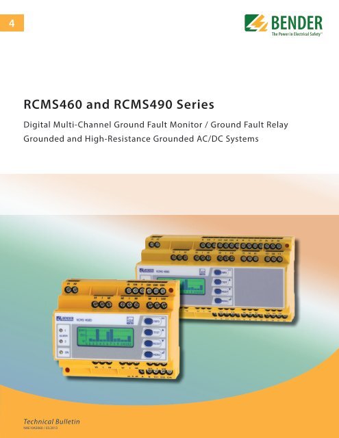
RCMS460 and RCMS490 Series<br />
Digital Multi-Channel Ground Fault Monitor / Ground Fault Relay<br />
Grounded and High-Resistance Grounded AC/DC Systems<br />
<strong>Technical</strong> <strong>Bulletin</strong><br />
NAE1042060 / 03.2013
BENDER Inc. • 700 Fox Chase, Coatesville PA 19320 • Ph: 800-356-4266 / 610-383-9200 • Fax: 610-383-7100<br />
RCMS460 / RCMS490 Series<br />
Multi-Channel Ground Fault Monitors<br />
for Grounded AC, DC, and AC/DC Systems<br />
RCMS460-D / -L and RCMS460-D / -L<br />
Device features<br />
• Selectably monitor either pure AC, pure DC,<br />
or AC/DC mix on each separate channel<br />
• True RMS value measurement<br />
• 12 separate monitoring channels, each with<br />
its own settings adjustment<br />
• AC ground fault detection up to 2000 Hz<br />
• Fast parallel scanning for all channels<br />
• Response ranges<br />
10 mA…10 A (DC or AC/DC mix)<br />
6 mA…20 A (AC only systems)<br />
• Latching or non-latching operation<br />
• Three separately adjustable time delays<br />
• Adjustable frequency behavior for<br />
protec tion of persons, fire protection and<br />
plant protection<br />
• History memory with date and time<br />
stamp for 300 data records<br />
• Data logger for 300 data records / channel<br />
• Analysis of harmonics, DC, THD<br />
• Two Voltage-free SPDT contacts for<br />
entire device<br />
• RCMS490: Additionally one voltage-free<br />
SPST contact for each channel<br />
• Selectable between normally energized<br />
and normally de energized operation<br />
• TEST / RESET button, internal / external<br />
• -D version: Digital backlit LCD display<br />
• Data exchange via BMS bus<br />
• Password protection<br />
• Continuous CT connection monitoring<br />
• Conforms to RoHS<br />
Approvals<br />
Description<br />
The RCMS460 and RCMS490 monitor for ground faults in multiple grounded and high-resistance<br />
grounded AC, DC, and AC/DC systems. The RCMS460 and RCMS490 are specifically designed<br />
to provide advanced warning of developing ground faults without the problems associated<br />
with high sensitivity nuisance tripping.<br />
Each RCMS device can monitor up to 12 circuits. Each channel can be separately adjusted<br />
to whether it is monitoring pure AC, pure DC, or mixed AC/DC. Setpoints are also separately<br />
adjustable on each channel. AC systems up to 2000 Hz can be monitored. Values<br />
are read as true RMS values.<br />
The RCMS460 has 2 common SPDT contacts for the device. The RCMS490 has 2 common<br />
SPDT contacts, as well as separate SPST contacts for each channel. The common SPDT<br />
contacts may be set for normally energized or de-energized operation, as well as latching<br />
or non-latching operation.<br />
The -D series features a high quality, backlit LCD display. Detailed analyses are available<br />
for each separate channel, as well as for any harmonics that may be on the system. A fullfeatured<br />
onboard menu combines ease of use with flexibility of settings.<br />
In addition, the RCMS series can be used for over- and undercurrent protection on single<br />
conductors. An option to use an x/5 ratio current transformer (programmable into the device)<br />
allows for a wide range of load currents to be monitored.<br />
Applications<br />
• Ground fault detection on multiple systems with single- or three-phase<br />
AC (up to 2000 Hz), pure DC, or mixed of AC and DC power<br />
• Generators<br />
• Motors and motor control centers<br />
• Industrial controls<br />
• Heat tracing systems<br />
• Over- and undercurrent protection on single conductors<br />
Function<br />
Measurements of the system's ground fault current are taken via external current transformers.<br />
On the -D version, each channel's current value is displayed in graphical form.<br />
If the measured value exceeds the response value for one or more channels, the common<br />
main alarm SPDT contact will switch over, and an alarm message for that channel will display<br />
on the LCD screen. The common alarm LED will also illuminate. On the RCMS490,<br />
the channel's corresponding SPST contact will also switch over. If the channel is set to<br />
non-latching mode and the ground fault clears, the alarms will then clear. If the channel<br />
is set to latching mode, the alarms will not clear until the device is reset manually or the<br />
supply voltage is lost.<br />
The device features three separately adjustable time delays: Startup delay (while RCMS is<br />
starting), response delay (after alarm is found), and delay on release (after alarm clears).<br />
The TEST function allows for an internal operation testing of the device. The device's easy<br />
to use onboard menu manages all settings via the detailed LCD display. An optional password<br />
protection setting protects unauthorized users from changing settings.<br />
One current transformer is required for each channel. All legs / phases are placed<br />
through the current transformer. Depending on the type of circuit being monitored, one<br />
of the following CTs is required (CTs are interchangeable for each separate channel):<br />
AC-only systems:<br />
• W series (circular type)<br />
• WR series (rectangular type)<br />
• WS series (split-core type)<br />
DC or mixed AC/DC systems:<br />
• WAB series<br />
• In addition, for each set of 6 WAB<br />
transformers, one AN420 is required.<br />
2
Ground fault monitors RCMS460-D / -L and RCMS490-D / -L<br />
History memory in RCMS460-D, RCMS490-D<br />
The -D version features a history memory storing up to 300 data records<br />
per channel (date, time, channel, event code, measured value)<br />
in nonvolatile memory. Data can be accessed either on board the<br />
device or through one of BENDER's protocol converters.<br />
Analysis of harmonics<br />
The analysis of the harmonics of the measured currents can be selected<br />
via a menu item in the -D versions. The DC component, the<br />
THD factor and the current value of the harmonics (1…40 at 50 / 60<br />
Hz, 1…5 at 400 Hz) are displayed numerically and graphically.<br />
Model variations<br />
RCMS460-D<br />
The RCMS460-D utilizes a digital, backlit LCD display with a full-featured<br />
menu for settings for each separate channel. Graphs of each<br />
separate channel as well as the harmonics can be displayed. In addition,<br />
one RCMS460 can apply settings across multiple interconnected<br />
RCMS devices. A common DPDT contact is available on the<br />
device.<br />
RCMS460-L<br />
The RCMS460-L utilizes a two-digit 7 segment display where the address<br />
of this device is displayed within the BMS bus. The alarm LEDs<br />
indicate the measuring where the response value has been exceeded.<br />
This unit requires at least one -D be on the system.<br />
RCMS490-D / RCMS490-L<br />
The RCMS490-D and -L versions correspond with the RCMS460 units<br />
above. In addition, one SPST contact is available for each channel.<br />
Overview of device types<br />
Distinctive device features RCMS460-D RCMS460-L RCMS490-D RCMS490-L<br />
Ground fault setpoint ranges<br />
DC and mixed AC/DC, AB type curernt transformers (type B)<br />
AC-only system, standard current transformers (type A)<br />
10 mA…10 A<br />
6 mA…20 A<br />
10 mA…10 A<br />
6 mA…20 A<br />
10 mA…10 A<br />
6 mA…20 A<br />
10 mA…10 A<br />
6 mA…20 A<br />
Allows for digital inputs × × × ×<br />
Backlit, digital LCD display × -- × --<br />
7-segment display and LED line -- × -- ×<br />
Paramater setting onboard device × -- × --<br />
Password protection × -- × --<br />
Display error code × × × ×<br />
Address range 1…90 1…90 1…90 1…90<br />
Master / slave operating principle × × × ×<br />
Internal clock × -- × --<br />
Common alarm relay(s) for all channels 2 SPDT contacts 2 SPDT contacts 2 SPDT contacts 2 SPDT contacts<br />
Alarm relay per channel -- -- 12 SPST contacts 12 SPST contacts<br />
Analysis of harmonics I Δn, DC, THD × --* × --*<br />
History memory 300 data records (overall) × -- × --<br />
Data logger for 300 data records (per channel) × -- × --<br />
PRESET function × --* × --*<br />
Number of measuring channels 12 12 12 12<br />
Enclosure type XM460 XM460 XM490 XM490<br />
* only in combination with RCMS4…-D<br />
3
Ground fault monitors RCMS460-D / -L and RCMS490-D / -L<br />
Operating and display elements: RCMS460-D / -L and RCMS490-D / -L<br />
1<br />
2<br />
3<br />
4<br />
5<br />
6<br />
7<br />
8<br />
10<br />
9<br />
1 - LED “ALARM 2”: Illuminates when the measured value<br />
"Alarm" of any channel has been exceeded.<br />
2 - LED “ALARM 1”: Illuminates when the measured value<br />
"Prewarning" of any channel has been exceeded.<br />
3 - LED “ON”: Illuminates when power is received to the unit.<br />
4 - Backlit LCD display<br />
5 - INFO key: Displays pertinent system information<br />
(does not apply to RCMS4…-L)<br />
ESC key: Exits the menu without changing parameters<br />
6 - TEST button: Activates self-test<br />
Arrow up key: Scrolls up inside device's menu<br />
7 - RESET button: Resets device<br />
Down key: Scrolls down inside device's menu<br />
8 - MENU key: Toggles between the standard display, the device's<br />
internal menu, and alarm display.<br />
(does not apply to RCMS4. . .-L)<br />
SET key: Sets addresses of -L devices on the system<br />
Enter key: Confirm change inside device's menu<br />
9 - Alarm LEDs “1…12” : Illuminate when the corresponding<br />
channel has a ground fault. Flashes when the corresponding<br />
channel has a current transformer connection error. (-L only)<br />
10 - Seven-segment display for device address and error codes<br />
(-L only)<br />
4
Ground fault monitors RCMS460-D / -L and RCMS490-D / -L<br />
Wiring diagram: RCMS460-D / -L Wiring diagram: RCMS490-D / -L<br />
2<br />
2<br />
9<br />
1<br />
8<br />
6 7 1<br />
8<br />
3 4 5<br />
6 7<br />
3 4 5<br />
1 - External supply voltage used to power device<br />
6 A fuse recommended for internal short circuit protection<br />
2 - Connections for current transformers CT1…CT12. Either Type<br />
A or Type B measuring current transformers can be selec ted<br />
for each measuring channel. Six W…AB series measuring<br />
current transformers require one AN420-2 power supply unit.<br />
3 - RS-485 interface (using the BMS bus protocol)<br />
4 - External reset button (normally de-energized contact)<br />
5 - External test button (normally de-energized contact); the external<br />
T / R cannot be connected in parallel to other devices.<br />
6 - Alarm relay K1: ALARM 1, common alarm for prewarning or<br />
alarm device error<br />
7 - Alarm relay K2: ALARM 2, common alarm for prewarning or<br />
alarm device error<br />
8 - R on / off: Activate or deactivate the BMS bus terminating resistor (120 Ω)<br />
9 - SPST contacts (normally de-energized operation, 490 only)<br />
5
Ground fault monitors RCMS460-D / -L and RCMS490-D / -L<br />
Wiring, current transformers: W, WR, WS series<br />
(AC-only systems, type A)<br />
Example: W series<br />
Wiring diagram, current transformers: WAB series<br />
(DC and AC/DC mix, type B)<br />
Wiring, current transformers: WF series<br />
Wiring: digital inputs<br />
Current<br />
Transformer<br />
WF...<br />
1 2<br />
Loads<br />
Signal Converter<br />
RCC420<br />
Ground Fault Monitor<br />
RCMS460 / RCMS490<br />
Optional analog output<br />
1 - Voltage-free contact<br />
0 > 250 Ω<br />
I < 100 Ω<br />
2 - Current transformer input for next channel<br />
6
Ground fault monitors RCMS460-D / -L and RCMS490-D / -L<br />
Example system: RCMS460-D monitoring 7 channels of differing types<br />
Current transformers<br />
for AC/DC loads (0 2000 Hz)<br />
Grounded System<br />
Current transformers<br />
for AC loads (42 2000 Hz)<br />
1<br />
Frequency settings<br />
The frequency response of the equipment can be set to a linear frequency response (up to the maximum frequency of 2000 Hz) if used<br />
for fire protection or to a frequency response in accordance with IEC 60990 for personnel protection. For plant protection, the ground<br />
fault current is measured up to the rated system frequency. The figure below shows the corresponding frequency response.<br />
Frequency curves and filter settings<br />
1<br />
2<br />
3<br />
4<br />
Response factor = I ∆ / I∆n<br />
(I∆) Ground fault current:<br />
Measured value at which the RCMS<br />
responds.<br />
(I ∆n) Rated ground fault current:<br />
Set response value<br />
1 - Menu selection “50 Hz”<br />
– Plant protection: Only evaluates the<br />
fundamental component of the ground<br />
fault current.<br />
2 - Menu selection “60 Hz”<br />
– Plant protection: Only evaluates the<br />
fundamental component of the ground<br />
fault current.<br />
3 - Menu selection “IEC”<br />
– Touch current for let-go (protection<br />
of persons) in accordance with IEC 60990<br />
4 - Menu selection “None”<br />
– Fire protection: Response factor<br />
remains the same over the entire<br />
frequency range.<br />
7
Ground fault monitors RCMS460-D / -L and RCMS490-D / -L<br />
8<br />
<strong>Technical</strong> data<br />
Insulation coordination acc. to IEC 60664-1 / IEC 60664-3<br />
Rated insulation voltage<br />
250 V<br />
Rated impulse voltage / pollution degree<br />
4 kV / III<br />
Protective separation (reinforced insulation) between<br />
(A1, A2) – (k1 / l…k12 / R / RT / T, AB) – (11, 12, 14) – (21, 22, 24)<br />
Voltage test according to IEC 61010-1<br />
2.21 kV<br />
Supply voltage<br />
Supply voltage U S<br />
see ordering information<br />
Frequency range U S <br />
see ordering information<br />
Power consumption <br />
≤ 5 VA (RCMS460) / ≤ 8 VA (RCMS490)<br />
Measuring circuit<br />
External current transformer W…, WR…, WS… series (Type A)<br />
W…AB series (Type B)<br />
CT monitoring<br />
on / off (on)*<br />
Load68 Ω<br />
Rated insulation voltage (measuring current transformer) <br />
800 V<br />
Operating characteristic acc. to IEC 60755<br />
Type A and Type B<br />
<br />
depending on the CT type (Type A)*<br />
Rated frequency 0…2000 Hz (Type B) / 42…2000 Hz (Type A)<br />
Cut-off frequency<br />
none, IEC, 50 Hz, 60 Hz (none)*<br />
Measuring range 0…30 A (CT Type A) – 0…20 A (CT Type B)<br />
crest factor up to 10 A = 4, up to 20 A = 2<br />
Rated residual operating current I Δn2 (Alarm) 10 mA…10 A (Type B)<br />
<br />
6 mA…20 A (Type A) (100 mA overcurrent)*<br />
Rated residual operating current I Δn1 (prewarning) <br />
10…100 % x I Δn2<br />
min 5 mA (50 %)*<br />
Digital input 1 < 100 Ω – 0 > 250 Ω<br />
Preset for alarm Offset: 0…20 A (30 mA)* and I Δ x factor 1…99 (3)*<br />
Preset for digital input<br />
0 / I (I)*<br />
Relative percentage error 0…- 20 %<br />
Hysteresis 2…40 % (20 %)*<br />
Factor for additional CT 1…10; x 1…250 (x 1)*<br />
Number of measuring channels (per device / system) 12 / 1080<br />
Specified time<br />
Starting delay t (startup) per device<br />
0…99 s (0 ms)*<br />
Response delay t on per channel<br />
0…999 s (200 ms)*<br />
Release delay t off per channel<br />
0…999 s (200 ms)*<br />
Operating time t ae at IΔn = 1 x IΔn1 / 2 <br />
≤ 180 ms<br />
Operating time t ae at IΔn = 5 x IΔn1 / 2 <br />
≤ 30 ms<br />
Response time t an (IΔn)tan = tae + ton1 / 2<br />
Operating time I / 0 inputs<br />
< 3,5 s<br />
Scanning time for all channels (I Δn)<br />
≤ 180 ms<br />
Recovery time t b<br />
500…600 ms<br />
Displays, memory<br />
Display range measured value 0…30 A (CT Type A) – 0…20 A (CT Type B)<br />
Display accuracy ± 10 %<br />
LEDs<br />
ON / ALARM (RCMS4…-D)<br />
<br />
ON / ALARM / channel 1…12 (RCMS4…-L)<br />
LC display<br />
backlit graphical display (RCMS4…-D)<br />
7-segment display<br />
2 x 7.62 mm (RCMS4…-L)<br />
History memory <br />
300 data records (RCMS4…-D)<br />
Data logger <br />
300 data records per channel (RCMS4…-D)<br />
Password <br />
off / 0…999 (off)*<br />
Language<br />
D, GB, F (GB)*<br />
Fault memory alarm relay <br />
on / off (off)*<br />
Inputs / outputs<br />
TEST / RESET button<br />
internal / external<br />
Cable length for external TEST / RESET button 0…32 ft (0…10 m)<br />
Interface<br />
Interface / protocol <br />
RS-485 / BMS<br />
Baud rate <br />
9600 baud<br />
Cable length <br />
0…1200 m<br />
Recommended cable (shielded, shield on one side connected to ground) J-Y(ST)Y min. 2 x 0.8<br />
Terminating resistor<br />
120 Ω (0.25 W) can be connected via DIP switch<br />
Device address, BMS bus (RCMS…-D / -L) 1…90 (2)*<br />
Cable lengths for measuring current transformers W…, WR…, WS…<br />
Single wire ≥ AWG 18 (0.75 mm 2 ) 0 . . . 3 ft (0…1 m)<br />
Single wire, twisted ≥ AWG 18 (0.75 mm 2 ) 0 . . . 32 ft (0…10 m)<br />
Shielded cable ≥ AWG 20 (0.5 mm 2 ) 0 . . . 130 ft (0…40 m)<br />
Recommended cable (shielded, shield on one side to terminal l, not connected to ground) J-Y(ST)Y min. 2 x 0.8<br />
Cable lengths for measuring current transformers W…AB<br />
Single wire ≥ AWG 18 (0.75 mm 2 ) 0…32 ft (0…10 m)<br />
Connection<br />
plug-in connector, recommended WXS…<br />
Switching elements<br />
Number of changeover contacts <br />
2 SPDT contacts (RCMS460)<br />
<br />
2 SPDT contacts, 12 SPST contacts (RCMS490)<br />
Operating principle <br />
normally energized or de-energized<br />
Electrical service life under rated operating conditions<br />
10.000 switching operations<br />
Contact data acc. to IEC 60947-5-1<br />
Utilization category AC-13 AC-14 DC-12 DC-12 DC-12<br />
Rated operational voltage 230 V 230 V 24 V 110 V 220 V<br />
Rated operational current 5 A 3 A 1 A 0.2 A 0.1 A<br />
Minimum contact load<br />
1 mA at AC / DC ≥ 10 V<br />
Environment / EMC<br />
EMC IEC 62020: 2003-11<br />
Operating temperature - 13 °F…+ 131 °F (- 25 °C…+ 55 °C )<br />
Climatic class acc. to IEC 60721<br />
Stationary use (IEC 60721-3-3)<br />
3K5 (except condensation and formation of ice)<br />
Transport (IEC 60721-3-2)<br />
2K3 (except condensation and formation of ice)<br />
Long-time storage (IEC 60721-3-1)<br />
1K4 (except condensation and formation of ice)<br />
Classification of mechanical conditions IEC 60721<br />
Stationary use (IEC 60721-3-3)<br />
3M4<br />
Transport (IEC 60721-3-2)<br />
2M2<br />
Long-time storage (IEC 60721-3-1)<br />
1M3<br />
Connection<br />
Connection<br />
screw terminals<br />
rigid / flexible AWG 24…12 / 24 . . . 14<br />
Multi-conductor connection (two conductors of the same cross section)<br />
rigid / flexible AWG 24…12 / 24…12<br />
Stripping length<br />
8…9 mm<br />
Tightening torque<br />
0.5…0.6 Nm<br />
Other<br />
Operating mode<br />
continuous operation<br />
Position of normal use<br />
any<br />
Degree of protection, internal components (IEC 60529) IP30, NEMA 1<br />
Degree of protection, terminals (IEC 60529) IP20, NEMA 1<br />
Enclosure material<br />
polycarbonate<br />
Flammability class<br />
UL94V-0<br />
Screw mounting<br />
2 x M4<br />
DIN rail mounting acc. to IEC 60715<br />
Standards IEC 62020<br />
<strong>Technical</strong> manual TGH 1393<br />
Weight <br />
≤ 0.8 lb (RCMS460)<br />
<br />
≤ 1.2 lb (RCMS490)<br />
( )* Factory setting
Ground fault monitors RCMS460-D / -L and RCMS490-D / -L<br />
Ordering information<br />
Type Supply voltage U S* Art. No.<br />
RCMS460-D-1 DC 16…94 V AC 42…460 Hz 16…72 V B 9405 3001<br />
RCMS460-D-2 DC 70…276 V AC 42…460 Hz 70…276 V B 9405 3002<br />
RCMS460-L-1 DC 16…94 V AC 42…460 Hz 16…72 V B 9405 3003<br />
RCMS460-L-2 DC 70…276 V AC 42…460 Hz 70…276 V B 9405 3004<br />
RCMS490-D-1 DC 16…94 V AC 42…460 Hz 16…72 V B 9405 3005<br />
RCMS490-D-2 DC 70…276 V AC 42…460 Hz 70…276 V B 9405 3006<br />
RCMS490-L-1 DC 16…94 V AC 42…460 Hz 16…72 V B 9405 3007<br />
RCMS490-L-2 DC 70…276 V AC 42…460 Hz 70…276 V B 9405 3008<br />
Type Supply voltage U S* Art. No.<br />
AN420-2<br />
DC 70…276 V /<br />
B 9405 3100<br />
(power supply unit for six W…AB)<br />
AC 42…460 Hz 70…276 V<br />
Accessories<br />
Type<br />
Art. No.<br />
Mounting clip for enclosure XM420<br />
B 9806 0008<br />
(1 piece per device)<br />
Snap-on mounting for W20… / W35… B 9808 0501<br />
Snap-on mounting for W60… B 9808 0502<br />
For further information about measuring current transformers,<br />
please refer to the respective data sheets.<br />
Dimensions: RCMS<br />
Dimensions in inches (mm)<br />
2.9”<br />
(74)<br />
1.9” (47.5)<br />
1.2” (31)<br />
4.25” (108)<br />
Connector cable for RCMS, "AB" type current transformers,<br />
and AN420 power supply<br />
Type Length in ft (m) Ordering No.<br />
WXS-100 3.2' (1) B 5111 00028<br />
WXS-250 8.2' (2.5) B 5111 00029<br />
WXS-500 16.4' (5) B 5111 00030<br />
WXS-1000 32.8' (10) B 5111 00027<br />
2.7” (67.5)<br />
1.8” (45)<br />
Ø 0.18”<br />
(4.5) 3.9” (98)<br />
3” (77)<br />
3.5” (90)<br />
Current transformers, DC and AC/DC mix (Type B)<br />
Type Inside diameter in inches (mm) Ordering No.<br />
W20AB ø 0.75" (20) B 9808 0008<br />
W35AB ø 1.35" (35) B 9808 0016<br />
W60AB ø 2.25" (60) B 9808 0026<br />
W120AB ø 4.7" (120) B 9808 0041<br />
W210AB ø 8.25" (210) B 9808 0040<br />
2.7” (67.5)<br />
1.8” (45)<br />
2.9”<br />
(74)<br />
1.9” (47.5)<br />
1.2” (31)<br />
6.4” (162)<br />
3” (77)<br />
3.5” (90)<br />
Current transformers, AC-only system (Type A)<br />
Type Inside diameter in inches (mm) Ordering No.<br />
W20 ø 0.75" (20) B 9808 0003<br />
W35 ø 1.35" (35) B 9808 0010<br />
W60 ø2.25" (60) B 9808 0018<br />
W120 ø 4.7" (120) B 9808 0028<br />
W210 ø 8.25" (210) B 9808 0034<br />
WR70x175 2.75" x 6.9" (70 x 175) B 9808 0609<br />
WR115x305 4.5" x 12" (115 x 305) B 9808 0610<br />
WS20x30 (split-core) 0.75" x 1.35" (20 x 30) B 9808 0601<br />
WS50x80 (split-core) 2" x 3.1" (50 x 80) B 9808 0603<br />
WS80x120 (split-core) 3.1" x 4.7" (80 x 120) B 9808 0606<br />
Other current transformer types on request.<br />
Ø 0.18”<br />
(4.5)<br />
Dimensions: AN420<br />
Dimensions in inches (mm)<br />
Open the front plate cover in<br />
direction of arrow.<br />
5.9” (98)<br />
2.66” (67.5)<br />
1.77” (45)<br />
2.78”<br />
(70.5)<br />
1.87”<br />
(47.5)<br />
1.42” (36)<br />
1.22” (31.1)<br />
3.54” (90)<br />
9
USA • Coatesville, PA<br />
Toll-Free: 800-356-4266 • Main: 610-383-9200<br />
Fax: 610-383-7100 • E-mail: info@bender.org<br />
T M<br />
bender.org • bender.org/mobile<br />
Canada • Mississauga, ON<br />
Toll-Free: 800-243-2438 • Main: 905-602-9990<br />
Fax: 905-602-9960 • E-mail: info@bender-ca.com<br />
Document NAE1042060 / 03.2013 / © <strong>Bender</strong> Inc.


