Connectors - NEXCOM
Connectors - NEXCOM
Connectors - NEXCOM

Create successful ePaper yourself
Turn your PDF publications into a flip-book with our unique Google optimized e-Paper software.
<strong>NEXCOM</strong> International Co., Ltd.<br />
Mobile Computing Solutions<br />
Fanless Railway Computer<br />
nROK 3000<br />
User Manual<br />
<strong>NEXCOM</strong> International Co., Ltd.<br />
Published March 2012<br />
www.nexcom.com
Contents<br />
Contents<br />
Preface<br />
Copyright .................................................................................................... iv<br />
Disclaimer .................................................................................................... iv<br />
Acknowledgements ...................................................................................... iv<br />
Regulatory Compliance Statements .............................................................. iv<br />
Declaration of Conformity ............................................................................. iv<br />
RoHS Compliance .......................................................................................... v<br />
Warranty and RMA ....................................................................................... vi<br />
Safety Information .......................................................................................vii<br />
Installation Recommendations .......................................................................vii<br />
Safety Precautions ........................................................................................viii<br />
Technical Support and Assistance .................................................................. ix<br />
Conventions Used in this Manual .................................................................. ix<br />
Global Service Contact Information ................................................................ x<br />
Package Contents .........................................................................................xii<br />
Ordering Information ...................................................................................xiii<br />
Chapter 1: Product Introduction<br />
Overview .......................................................................................................1<br />
Key Features ................................................................................................1<br />
Hardware Specifications .................................................................................3<br />
Getting to Know nROK 3000 .........................................................................4<br />
Front Panel ..................................................................................................4<br />
Rear Panel ...................................................................................................8<br />
Chapter 2: Jumpers and <strong>Connectors</strong><br />
Before You Begin ........................................................................................10<br />
Precautions .................................................................................................10<br />
Jumper ........................................................................................................11<br />
Locations of the Jumpers and <strong>Connectors</strong> ....................................................12<br />
Jumper Settings ...........................................................................................13<br />
IGNITION Select (JP7) .................................................................................13<br />
IGNITION Select ( JP8) (default NC)...........................................................13<br />
CMOS Input Voltage Select (J3)..................................................................13<br />
TEMP SENSOR (JP5) ...................................................................................13<br />
PCI104 VI/O Select Voltage (J9 ) .................................................................13<br />
MCU Download (JP4) ................................................................................13<br />
GAL Download (JP2) ..................................................................................13<br />
MCU COM PORT (JP6) ...............................................................................13<br />
<strong>Connectors</strong> ..................................................................................................14<br />
UART CONNECTOR (RS232/422/485&GPIO) (CN1) ...................................14<br />
DVI+VGA CONNECTOR (CN2) .................................................................14<br />
GPS Connector COM6 (J4) ........................................................................15<br />
AUDIO CONNECTOR (J11) ........................................................................15<br />
GAL Programmer PIN Header (JP2) .............................................................16<br />
MCU Programmer PIN Header (JP4) ...........................................................16<br />
LAN connector (J5)(J7)(J8) ..........................................................................17<br />
FRONT USB connector (J10) .......................................................................17<br />
REAR USB connector (USB1) .....................................................................18<br />
PCI-104 VI/O voltage setting (J9) ................................................................18<br />
Copyright © 2012 <strong>NEXCOM</strong> International Co., Ltd. All rights reserved ii nROK 3000 User Manual
Contents<br />
PCI-104 connector (CN21) ........................................................................ 19<br />
RESET BUTTON (SW2) .............................................................................. 20<br />
MCU COM PORT (JP6) .............................................................................. 20<br />
TEMP SENSOR (JP5) .................................................................................. 21<br />
POWER INPUT .......................................................................................... 21<br />
+12V DC Power Input Connector (CON1) ................................................. 21<br />
12VSD DC Power Input Connector (CON2) .............................................. 22<br />
12VSD GPIO (J6) ....................................................................................... 22<br />
POWER ON ,HD ,WWAN ,WLAN Active LED (LED1) .................................. 23<br />
Serial-ATA (CN3) ....................................................................................... 23<br />
Serial-ATA POWER INPUT (J1) .................................................................... 24<br />
Mini-PCIe (3.5G)(CN6) .............................................................................. 24<br />
Mini-PCIe (WLAN)(CN7) ............................................................................ 25<br />
SIM CARD CONNECTOR (CN4) (CN5) ....................................................... 25<br />
Chapter 3: System Setup<br />
Removing the Chassis Cover ........................................................................26<br />
Installing the Wi-Fi and GPRS/UMTS/HSDPA Modules ...................................28<br />
Installing SSD Drive ......................................................................................29<br />
Rackmount Brackets ....................................................................................31<br />
Appendix A: I/O Address Function<br />
I/O Address Function ....................................................................................32<br />
Appendix B: Power Consumption<br />
Power Consumption ....................................................................................36<br />
Copyright © 2012 <strong>NEXCOM</strong> International Co., Ltd. All rights reserved iii nROK 3000 User Manual
Preface<br />
PrefaCe<br />
Copyright<br />
This publication, including all photographs, illustrations and software, is<br />
protected under international copyright laws, with all rights reserved. No<br />
part of this manual may be reproduced, copied, translated or transmitted<br />
in any form or by any means without the prior written consent from<br />
<strong>NEXCOM</strong> International Co., Ltd.<br />
Disclaimer<br />
The information in this document is subject to change without prior notice<br />
and does not represent commitment from <strong>NEXCOM</strong> International Co.,<br />
Ltd. However, users may update their knowledge of any product in use by<br />
constantly checking its manual posted on our website: http://www.nexcom.<br />
com. <strong>NEXCOM</strong> shall not be liable for direct, indirect, special, incidental, or<br />
consequential damages arising out of the use of any product, nor for any<br />
infringements upon the rights of third parties, which may result from such<br />
use. Any implied warranties of merchantability or fitness for any particular<br />
purpose is also disclaimed.<br />
Acknowledgements<br />
nROK 3000 is a trademark of <strong>NEXCOM</strong> International Co., Ltd. All other product<br />
names mentioned herein are registered trademarks of their respective owners.<br />
Regulatory Compliance Statements<br />
This section provides the FCC compliance statement for Class A devices and<br />
describes how to keep the system CE compliant.<br />
Declaration of Conformity<br />
Copyright © 2012 <strong>NEXCOM</strong> International Co., Ltd. All rights reserved iv<br />
nROK 3000 User Manual<br />
FCC<br />
This equipment has been tested and verified to comply with the limits for<br />
a Class A digital device, pursuant to Part 15 of FCC Rules. These limits are<br />
designed to provide reasonable protection against harmful interference when<br />
the equipment is operated in a commercial environment. This equipment<br />
generates, uses, and can radiate radio frequency energy and, if not installed<br />
and used in accordance with the instructions, may cause harmful interference<br />
to radio communications. Operation of this equipment in a residential area<br />
(domestic environment) is likely to cause harmful interference, in which<br />
case the user will be required to correct the interference (take adequate<br />
measures) at their own expense.<br />
CE<br />
The product(s) described in this manual complies with all applicable<br />
European Union (CE) directives if it has a CE marking. For computer systems<br />
to remain CE compliant, only CE-compliant parts may be used. Maintaining<br />
CE compliance also requires proper cable and cabling techniques.
Preface<br />
RoHS Compliance<br />
<strong>NEXCOM</strong> RoHS Environmental Policy and Status Update<br />
<strong>NEXCOM</strong> is a global citizen for building the digital<br />
infrastructure. We are committed to providing green<br />
products and services, which are compliant with<br />
European Union RoHS (Restriction on Use of Hazardous<br />
Substance in Electronic Equipment) directive 2002/95/<br />
EU, to be your trusted green partner and to protect<br />
our environment.<br />
RoHS restricts the use of Lead (Pb) < 0.1% or 1,000ppm, Mercury (Hg)<br />
< 0.1% or 1,000ppm, Cadmium (Cd) < 0.01% or 100ppm, Hexavalent<br />
Chromium (Cr6+) < 0.1% or 1,000ppm, Polybrominated biphenyls (PBB) <<br />
0.1% or 1,000ppm, and Polybrominated diphenyl Ethers (PBDE) < 0.1% or<br />
1,000ppm.<br />
In order to meet the RoHS compliant directives, <strong>NEXCOM</strong> has established an<br />
engineering and manufacturing task force in to implement the introduction<br />
of green products. The task force will ensure that we follow the standard<br />
<strong>NEXCOM</strong> development procedure and that all the new RoHS components<br />
and new manufacturing processes maintain the highest industry quality<br />
levels for which <strong>NEXCOM</strong> are renowned.<br />
The model selection criteria will be based on market demand. Vendors and<br />
suppliers will ensure that all designed components will be RoHS compliant.<br />
How to recognize <strong>NEXCOM</strong> RoHS Products?<br />
For existing products where there are non-RoHS and RoHS versions, the<br />
suffix “(LF)” will be added to the compliant product name.<br />
All new product models launched after January 2006 will be RoHS compliant.<br />
They will use the usual <strong>NEXCOM</strong> naming convention.<br />
Copyright © 2012 <strong>NEXCOM</strong> International Co., Ltd. All rights reserved v<br />
nROK 3000 User Manual
Preface<br />
Warranty and RMA<br />
<strong>NEXCOM</strong> Warranty Period<br />
<strong>NEXCOM</strong> manufactures products that are new or equivalent to new in<br />
accordance with industry standard. <strong>NEXCOM</strong> warrants that products will<br />
be free from defect in material and workmanship for 2 years, beginning on<br />
the date of invoice by <strong>NEXCOM</strong>. HCP series products (Blade Server) which<br />
are manufactured by <strong>NEXCOM</strong> are covered by a three year warranty period.<br />
<strong>NEXCOM</strong> Return Merchandise Authorization (RMA)<br />
? Customers shall enclose the “<strong>NEXCOM</strong> RMA Service Form” with the<br />
returned packages.<br />
? Customers must collect all the information about the problems<br />
encountered and note anything abnormal or, print out any on-screen<br />
messages, and describe the problems on the “<strong>NEXCOM</strong> RMA Service<br />
Form” for the RMA number apply process.<br />
? Customers can send back the faulty products with or without accessories<br />
(manuals, cable, etc.) and any components from the card, such as CPU<br />
and RAM. If the components were suspected as part of the problems,<br />
please note clearly which components are included. Otherwise, <strong>NEXCOM</strong><br />
is not responsible for the devices/parts.<br />
? Customers are responsible for the safe packaging of defective products,<br />
making sure it is durable enough to be resistant against further damage<br />
and deterioration during transportation. In case of damages occurred<br />
during transportation, the repair is treated as “Out of Warranty.”<br />
? Any products returned by <strong>NEXCOM</strong> to other locations besides the<br />
customers’ site will bear an extra charge and will be billed to the customer.<br />
Repair Service Charges for Out-of-Warranty Products<br />
<strong>NEXCOM</strong> will charge for out-of-warranty products in two categories, one is<br />
basic diagnostic fee and another is component (product) fee.<br />
System Level<br />
? Component fee: <strong>NEXCOM</strong> will only charge for main components such as<br />
SMD chip, BGA chip, etc. Passive components will be repaired for free,<br />
ex: resistor, capacitor.<br />
? Items will be replaced with <strong>NEXCOM</strong> products if the original one cannot<br />
be repaired. Ex: motherboard, power supply, etc.<br />
? Replace with 3 rd party products if needed.<br />
? If RMA goods can not be repaired, <strong>NEXCOM</strong> will return it to the customer<br />
without any charge.<br />
Copyright © 2012 <strong>NEXCOM</strong> International Co., Ltd. All rights reserved vi<br />
nROK 3000 User Manual
Preface<br />
Board Level<br />
? Component fee: <strong>NEXCOM</strong> will only charge for main components, such<br />
as SMD chip, BGA chip, etc. Passive components will be repaired for free,<br />
ex: resistors, capacitors.<br />
If RMA goods can not be repaired, <strong>NEXCOM</strong> will return it to the customer<br />
without any charge.<br />
Warnings<br />
Read and adhere to all warnings, cautions, and notices in this guide and<br />
the documentation supplied with the chassis, power supply, and accessory<br />
modules. If the instructions for the chassis and power supply are inconsistent<br />
with these instructions or the instructions for accessory modules, contact<br />
the supplier to find out how you can ensure that your computer meets<br />
safety and regulatory requirements.<br />
Cautions<br />
Electrostatic discharge (ESD) can damage system components. Do the<br />
described procedures only at an ESD workstation. If no such station is<br />
available, you can provide some ESD protection by wearing an antistatic<br />
wrist strap and attaching it to a metal part of the computer chassis.<br />
Safety Information<br />
Before installing and using the device, note the following precautions:<br />
? Read all instructions carefully.<br />
? Do not place the unit on an unstable surface, cart, or stand.<br />
? Follow all warnings and cautions in this manual.<br />
▪ When replacing parts, ensure that your service technician uses parts<br />
specified by the manufacturer.<br />
▪ Avoid using the system near water, in direct sunlight, or near a heating<br />
device.<br />
▪ The load of the system unit does not solely rely for support from the<br />
rackmounts located on the sides. Firm support from the bottom is highly<br />
necessary in order to provide balance stability.<br />
The computer is provided with a battery-powered real-time clock circuit.<br />
There is a danger of explosion if battery is incorrectly replaced. Replace<br />
only with the same or equivalent type recommended by the manufacturer.<br />
Discard used batteries according to the manufacturer’s instructions.<br />
Installation Recommendations<br />
Ensure you have a stable, clean working environment. Dust and dirt can get<br />
into components and cause a malfunction. Use containers to keep small<br />
components separated.<br />
Adequate lighting and proper tools can prevent you from accidentally<br />
damaging the internal components. Most of the procedures that follow<br />
require only a few simple tools, including the following:<br />
• A Philips screwdriver<br />
• A flat-tipped screwdriver<br />
• A grounding strap<br />
• An anti-static pad<br />
Using your fingers can disconnect most of the connections. It is recommended<br />
that you do not use needlenose pliers to disconnect connections as these<br />
can damage the soft metal or plastic parts of the connectors.<br />
Copyright © 2012 <strong>NEXCOM</strong> International Co., Ltd. All rights reserved vii<br />
nROK 3000 User Manual
Preface<br />
Safety Precautions<br />
1. Read these safety instructions carefully.<br />
2. Keep this User Manual for later reference.<br />
3. Disconnect this equipment from any AC outlet before cleaning. Use a<br />
damp cloth. Do not use liquid or spray detergents for cleaning.<br />
4. For plug-in equipment, the power outlet socket must be located near<br />
the equipment and must be easily accessible.<br />
5. Keep this equipment away from humidity.<br />
6. Put this equipment on a stable surface during installation. Dropping it<br />
or letting it fall may cause damage.<br />
7. Do not leave this equipment in either an unconditioned environment<br />
or in a above 40 o C storage temperature as this may damage the<br />
equipment.<br />
8. The openings on the enclosure are for air convection to protect the<br />
equipment from overheating. DO NOT COVER THE OPENINGS.<br />
9. Make sure the voltage of the power source is correct before<br />
connecting the equipment to the power outlet.<br />
10. Place the power cord in a way so that people will not step on it. Do<br />
not place anything on top of the power cord. Use a power cord that<br />
has been approved for use with the product and that it matches the<br />
voltage and current marked on the product’s electrical range label.<br />
The voltage and current rating of the cord must be greater than the<br />
voltage and current rating marked on the product.<br />
11. All cautions and warnings on the equipment should be noted.<br />
12. If the equipment is not used for a long time, disconnect it from the<br />
power source to avoid damage by transient overvoltage.<br />
13. Never pour any liquid into an opening. This may cause fire or electrical<br />
shock.<br />
14. Never open the equipment. For safety reasons, the equipment should<br />
be opened only by qualified service personnel.<br />
15. If one of the following situations arises, get the equipment checked by<br />
service personnel:<br />
a. The power cord or plug is damaged.<br />
b. Liquid has penetrated into the equipment.<br />
c. The equipment has been exposed to moisture.<br />
d. The equipment does not work well, or you cannot get it to work<br />
according to the user’s manual.<br />
e. The equipment has been dropped and damaged.<br />
f. The equipment has obvious signs of breakage.<br />
16. Do not place heavy objects on the equipment.<br />
17. The unit uses a three-wire ground cable which is equipped with a third<br />
pin to ground the unit and prevent electric shock. Do not defeat the<br />
purpose of this pin. If your outlet does not support this kind of plug,<br />
contact your electrician to replace your obsolete outlet.<br />
18. CAUTION: DANGER OF EXPLOSION IF BATTERY IS INCORRECTLY<br />
REPLACED. REPLACE ONLY WITH THE SAME OR EQUIVALENT TYPE<br />
RECOMMENDED BY THE MANUFACTURER. DISCARD USED BATTERIES<br />
ACCORDING TO THE MANUFACTURER’S INSTRUCTIONS.<br />
19. The computer is provided with CD drives that comply with the<br />
appropriate safety standards including IEC 60825.<br />
Copyright © 2012 <strong>NEXCOM</strong> International Co., Ltd. All rights reserved viii<br />
nROK 3000 User Manual
Preface<br />
Technical Support and Assistance<br />
1. For the most updated information of <strong>NEXCOM</strong> products, visit <strong>NEXCOM</strong>’s<br />
website at www.nexcom.com.<br />
2. For technical issues that require contacting our technical support team or<br />
sales representative, please have the following information ready before<br />
calling:<br />
– Product name and serial number<br />
– Detailed information of the peripheral devices<br />
– Detailed information of the installed software (operating system,<br />
version, application software, etc.)<br />
– A complete description of the problem<br />
– The exact wordings of the error messages<br />
Warning!<br />
1. Handling the unit: carry the unit with both hands and handle it with<br />
care.<br />
2. Maintenance: to keep the unit clean, use only approved cleaning<br />
products or clean with a dry cloth.<br />
3. CompactFlash: Turn off the unit’s power before inserting or removing a<br />
CompactFlash storage card.<br />
Conventions Used in this Manual<br />
Warning: Information about certain situations, which if not<br />
observed, can cause personal injury. This will prevent injury to<br />
yourself when performing a task.<br />
Caution: Information to avoid damaging components or losing<br />
data.<br />
Note: Provides additional information to complete a task easily.<br />
Copyright © 2012 <strong>NEXCOM</strong> International Co., Ltd. All rights reserved ix<br />
nROK 3000 User Manual<br />
CAUTION!<br />
Battery - Safety Measures<br />
Caution<br />
• Risk of explosion if battery is replaced by an incorrect type.<br />
• Dispose of used batteries according to the instructions.<br />
Safety Warning<br />
This equipment is intended for installation in a Restricted Access<br />
Location only.<br />
Resetting the Date and Time<br />
Note: Remember to reset the date and time upon receiving the<br />
product. You can set them in the AMI BIOS. Refer to chapter 4<br />
for more information.
Preface<br />
Global Service Contact Information<br />
Headquarters<br />
<strong>NEXCOM</strong> International Co, Ltd.<br />
15F,No.920,Chung-Cheng Road, Zhonghe Dist.<br />
New Taipei City, Taiwan 23586, R.O.C.<br />
Tel: +886-2-8226-7786<br />
Fax: +886-2-8226-7782<br />
sales@nexcom.com.tw<br />
www.nexcom.com.tw<br />
USA<br />
<strong>NEXCOM</strong> USA<br />
3758 Spinnaker Court, Fremont, CA 94538 USA<br />
Tel: +1-510-656-2248<br />
Fax: +1-510-656-2158<br />
sales@nexcom.com<br />
www.nexcom.com<br />
Japan<br />
<strong>NEXCOM</strong> Japan<br />
9F, Tamachi Hara Bldg., 4-11-5,Shiba Minato-ku, Tokyo, 108-0014, Japan<br />
Tel: +81-3-5419-7830<br />
Fax: +81-3-5419-7832<br />
sales@nexcom-jp.com<br />
www.nexcom-jp.com<br />
Copyright © 2012 <strong>NEXCOM</strong> International Co., Ltd. All rights reserved x<br />
nROK 3000 User Manual<br />
China<br />
<strong>NEXCOM</strong> China<br />
2F, Block 4, Venus Plaza, Building 21, ZhongGuanCun Software Park,<br />
No.8, Dongbeiwang West Road, Haidian District, Beijing, 100193, China<br />
Tel: +86-10-5885-6655<br />
Fax: +86-10-5885-1066<br />
sales@nexcom.cn<br />
www.nexcom.cn<br />
Shanghai Office<br />
Room 1505, Greenland He Chuang Building, No. 450 Caoyang Rd.<br />
Shanghai, 200062, China<br />
Tel: +86-21-6150-8008<br />
Fax: +86-21-3251-6358<br />
sales@nexcom.cn<br />
www.nexcom.cn<br />
Nanjing Office<br />
Hall C, Black 17, TianXingCuiLang, No. 49 Yunnan North Rd.<br />
Nanjing, 210018, China<br />
Tel: +86-25-8315-3486<br />
Fax: +86-25-8315-3489<br />
sales@nexcom.cn<br />
www.nexcom.cn
Preface<br />
Shenzhen Office<br />
West Room 708, Black 210,<br />
Tairan Industry&Trading Place, Fution Area,<br />
Shenzhen, 518040, China<br />
Tel: +86-755-833-27203<br />
Fax: +86-755-833-27213<br />
sales@nexcom.cn<br />
www.nexcom.cn<br />
France<br />
<strong>NEXCOM</strong> France<br />
Z.I. des Amandiers, 17,<br />
Rue des entrepreneurs<br />
78420 Carrières sur Seine, France<br />
Tel: +33 (0)1 71 51 10 20<br />
Fax: +33 (0)1 71 51 10 21<br />
sales.fr@nexcom.eu<br />
www.nexcom.eu<br />
Germany<br />
<strong>NEXCOM</strong> GmbH<br />
Leopoldstraße Business Centre,<br />
Leopoldstraße 244<br />
80807 Munich, Germany,<br />
Tel: +49-89-208039-278<br />
Fax: +49-89-208039-279<br />
sales.de@nexcom.eu<br />
www.nexcom.eu<br />
Copyright © 2012 <strong>NEXCOM</strong> International Co., Ltd. All rights reserved xi<br />
nROK 3000 User Manual<br />
Italy<br />
<strong>NEXCOM</strong> ITALIA S.r.l<br />
Via Gaudenzio Ferrari 29<br />
21047, Saronno(VA), Italia<br />
Tel: +39 02 9628 0333<br />
Fax: +39 02 9619 8846<br />
sales.it@nexcom.eu<br />
www.nexcom.eu<br />
United Kingdom<br />
<strong>NEXCOM</strong> EUROPE<br />
10 Vincent Avenue,<br />
Crownhill Business Centre<br />
Milton Keynes, Buckinghamshire<br />
MK8 0AB, United Kingdom<br />
Tel: +44-1908-267121<br />
Fax: +44-1908-262042<br />
sales.uk@nexcomuk.co.eu<br />
www.nexcomuk.co.eu
Preface<br />
Package Contents<br />
Before continuing, verify that the package that you received is complete. Your package should have all the items listed in the following table.<br />
Item P/N Name Specification Qty<br />
1 50311F0110X00 FLAT HEAD SCREW F3x5 NI NYLOK 4<br />
2 60233SAM05X00 GPS ANTENNA 5M /SMA180P 1<br />
3 602DCD0393X00 CD DRIVER 1<br />
Copyright © 2012 <strong>NEXCOM</strong> International Co., Ltd. All rights reserved xii<br />
nROK 3000 User Manual
Preface<br />
Ordering Information<br />
The following provides ordering information.<br />
• nROK 3000-A (P/N: 10A00300000X0)<br />
- Intel ® Atom D525 fanless railway computer with 24VDC isolation<br />
power input<br />
• nROK 3000-F (P/N: 10A00300001X0)<br />
- Intel ® Atom D525 fanless railway computer with 110VDC isolation<br />
power input<br />
• POWER CABLE (P/N: 60233PW243X00)<br />
- Waterproof 4P L:300mm<br />
• M12 TO USB CABLE (P/N: 60233USB89X00)<br />
- Waterproof M12 TO USB CON L:200mm<br />
• AUDIO CABLE (P/N: 60233AUD27X00)<br />
- Waterproof MINI SIZE 6P TO DC3.5mm FEMALEx2 L:300mm<br />
• DVI Y-CABLE (P/N: 60233DVI26X00)<br />
- Waterproof DVI(24+5P) to DVI(24+5P)/D-SUB(15P) L:100mm<br />
• COM CABLE (P/N: 6023331451X00)<br />
-Waterproof 31PIN to DB9 MALEx4/DB9 FEMALEx1 L=150mm<br />
Copyright © 2012 <strong>NEXCOM</strong> International Co., Ltd. All rights reserved xiii<br />
nROK 3000 User Manual
Chapter 1: Product Introduction<br />
ChaPter 1: ProduCt IntroduCtIon<br />
Overview<br />
Key Features<br />
• Built-in Intel ® Atom D525 Dual Core 1.8GHz processor<br />
• Fanless and rugged design<br />
• Availability of GPS, GPRS/ UMTS/ HSDPA<br />
• Multiple display connections: Dual VGA and DVI-D<br />
• PCI-104 and 2 x Mini card expension interface<br />
• Rich I/O interface with secure lock<br />
Front View Rear View<br />
• Isolation RS-232/ 422/ 485 and GPIO<br />
• Easy maintenance<br />
• Removable 2.5” SSD tray<br />
• Optional 24V/110V DC input with isolated protection<br />
• Compliant IP65 design<br />
• Certified by EN50155<br />
Copyright © 2012 <strong>NEXCOM</strong> International Co., Ltd. All rights reserved 1<br />
nROK 3000 User Manual
Chapter 1: Product Introduction<br />
The latest transportation computing solution nROK 3000 fanless computer<br />
certified with EN50155 is specially designed for railway related applications.<br />
Based on Intel ® Atom D525 processor, nROK 3000 is designed with isolated<br />
DC input protection to ensure stable operation in harsh environments.<br />
Adopting lock concept, all connectors, such as M12 Ethernet connector on<br />
nROK 3000, are designed for anti-vibration.<br />
Equipped with a SIM card holder, CFast socket and mini-PCIe socket for<br />
optional 3G wireless module, nROK 3000 allows data to be transmitted over<br />
network and stored in a convenient SSD (Solid-State Drive) or CFast card for<br />
better vibration and shock protection. The EN50155-certified nROK 3000 is<br />
a reliable solution for railway applications.<br />
Copyright © 2012 <strong>NEXCOM</strong> International Co., Ltd. All rights reserved 2<br />
nROK 3000 User Manual
Chapter 1: Product Introduction<br />
Hardware Specifications<br />
Main Chipset<br />
• Intel ® ICH-8M<br />
CPU<br />
• Intel ® Atom D525 Dual Core 1.8GHz<br />
Memory<br />
• 1GB DDR3 1333MHz SODIMM (up to 4GB)<br />
Expansion<br />
• Mini PCIe socket (USB) x 1 (for 3.5G module)<br />
• 1 x GPS module<br />
• Mini PCIe socket (PCIe + USB) x 1 (for WLAN module)<br />
I/O Interfaces - Front<br />
• 1 x DVI-I connector with DVI-D and VGA output<br />
• 1 x 26-pin circular connector in support of RS-232/ 422/ 485 with isolation,<br />
4-channel digital input and 4-channel digital output<br />
• 1 x USB 2.0 with M12 connector<br />
• 1 x Mic-in & 1 x Line-out<br />
• 3 x 10/100 Ethernet with M12 connector<br />
• Wireless communication<br />
1 x External accessible SIM card socket<br />
3 x Antenna holes for WWAN/ WLAN/ GPS<br />
• 4 x LED for power, SSD, WWAN and WLAN<br />
• DC Input<br />
24V with 500V isolated (range: 16.8V ~ 30V)<br />
Optional: 110V with 1.5KV isolation (range: 66V ~ 154V)<br />
I/O Interfaces - Rear<br />
• SSD accessible<br />
• 2 x USB 2.0<br />
Expandable Storage<br />
• 1 x SATA 2.5” SSD Bay<br />
• 1 x CFast slot with protection cover<br />
Dimensions<br />
• 260mm (W) x 178mm (D) x 70mm (H) (10.24”x 7”x 2.76”)<br />
Construction<br />
• Aluminum enclosure with fanless design<br />
Environment<br />
• Operating temperatures<br />
Ambient with air: -40°C to 55°C (EN50155 Class T2)<br />
• Storage temperatures: -40°C to 80°C<br />
• Damp heat test: 55°C, 95% RH (non-operating, EN 50155)<br />
• Relative humidity: 0% to 90% (non-condensing)<br />
• Vibration (random):<br />
Compliance with EN61373 Category 1 Class B<br />
• Shock:<br />
Compliance with EN61373 Category 1 Class B<br />
Certifications<br />
• CE approval<br />
• FCC Class A<br />
• Compliance with EN50155<br />
Copyright © 2012 <strong>NEXCOM</strong> International Co., Ltd. All rights reserved 3<br />
nROK 3000 User Manual
Chapter 1: Product Introduction<br />
Getting to Know nROK 3000<br />
Front Panel<br />
HSDPA<br />
antenna<br />
LEDs<br />
31pin<br />
connector<br />
DVI-D<br />
WiFi antenna<br />
SIM/ CFAST<br />
card socket<br />
Ethernet<br />
connectors<br />
Reset button<br />
GPS antenna<br />
Audio<br />
connector<br />
DC in 24V<br />
31pin Connector<br />
Pin Definition Pin Definition<br />
1 RS422_RX+_A 2 SP_TXD_1<br />
3 RS422_RX-_A 4 SP_RI_1<br />
5 RS422_TX+_A 6 SP_DTR_1<br />
7 RS422_TX-_A 8 SP_CTS_1<br />
9 RS485_TX+_A 10 SP_DCD_1<br />
11 RS485_TX-_A 12 SP_RTS_1<br />
13 RS4852_TX+_A 14 SP_RXD_1<br />
15 RS4852_TX-_A 16 SP_DSR_1<br />
17 NC 18 NC<br />
19 NC 20 NC<br />
21 ISO1_GND 22 ISO1_GND<br />
23 G_I_1 24 G_O_1<br />
25 G_I_2 26 G_O_2<br />
27 G_I_3 28 G_O_3<br />
29 G_I_4 30 G_O_4<br />
31 N/A<br />
Copyright © 2012 <strong>NEXCOM</strong> International Co., Ltd. All rights reserved 4<br />
nROK 3000 User Manual
Chapter 1: Product Introduction<br />
Getting to Know nROK 3000<br />
VGA and DVI Connector<br />
Pin Definition Pin Definition<br />
1 CH_TX2_N 2 CH_TX2_P<br />
3 CH_GND 4 NC<br />
5 NC 6 DVI_I_DDC_C_R<br />
7 DVI_I_DDC_D_R 8 VGA1_VSYNC<br />
9 CH_TX1_N 10 CH_TX1_P<br />
11 CH_GND 12 NC<br />
13 NC 14 VGA1_PWR_L<br />
15 CH_GND 16 HPDET_I<br />
17 CH_TX0_N 18 CH_TX0_P<br />
19 CH_GND 20 VGA1_DDCCLK<br />
21 VGA1_DDCDAT 22 NC<br />
23 CH_CLK_P 24 CH_CLK_N<br />
C1 VGA1_RED C2 VGA1_GREEN<br />
C3 VGA1_BLUE C4 VGA1_HSYNC<br />
C5 CH_GND; M_DET<br />
Audio Connector<br />
Pin Definition Pin Definition<br />
1 SURR_OUT_L_CA 2 SURR_JD<br />
3 SURR_OUT_R_CA 4 MIC_OUT-R<br />
5 MIC_JD 6 C_GND<br />
Copyright © 2012 <strong>NEXCOM</strong> International Co., Ltd. All rights reserved 5<br />
nROK 3000 User Manual
Chapter 1: Product Introduction<br />
Getting to Know nROK 3000<br />
M12 FOR LAN<br />
Pin Definition Pin Definition<br />
1 LAN_MDI_0P_R 2 LAN_MDI_1P_R<br />
3 LAN_MDI_0N_R 4 LAN_MDI_1N_R<br />
M12 FOR USB<br />
Pin Definition Pin Definition<br />
1 USB_0N 2 USB_VCC0<br />
3 USB_0P 4 UGND_1<br />
Copyright © 2012 <strong>NEXCOM</strong> International Co., Ltd. All rights reserved 6<br />
nROK 3000 User Manual
Chapter 1: Product Introduction<br />
Getting to Know nROK 3000<br />
POWER Connector<br />
Pin Definition Pin Definition<br />
1 DC INPUT + 2 DC INPUT -<br />
3 IGNITION SIGNAL INPUT 4 CHASSIS GND<br />
NOTE: Only nROK3000-A supports ignition function<br />
External POWER Cable<br />
Pin Definition Pin Definition<br />
1 DC INPUT +(RED) 2 DC INPUT –(BLACK)<br />
3<br />
IGNITION SIGNAL<br />
INPUT(YELLOW)<br />
4 CHASSIS GND(GREEN)<br />
SIM Card Socket<br />
nROK3000 can be internally integrated with a 3.5G Mini Card module.<br />
The SIM card bracket is on the board. When using the GPRS/UMTS/HSDPA<br />
function, insert the SIM card into the SIM card socket. Make sure to turn<br />
off nROK3000 before inserting the SIM card.<br />
CFast Socket<br />
nROK3000 provides CFast Socket, it can be used in storage and also can<br />
support system driver.<br />
Reset Button<br />
Press this button to restart nROK3000.<br />
WIFI/HSDPA Module Antenna Mounting Hole<br />
The antenna mounting holes are used to mount and connect antennas to<br />
the WIFI/HSDPA/ module.<br />
Copyright © 2012 <strong>NEXCOM</strong> International Co., Ltd. All rights reserved 7<br />
nROK 3000 User Manual
Chapter 1: Product Introduction<br />
Getting to Know nROK 3000<br />
Rear Panel Removable SSD tray<br />
Removable SSD tray<br />
USB connectors<br />
nROK 3000 allows data to be transmitted over network and stored in a<br />
convenient SSD (Solid-State Drive) or CFast card for better vibration and<br />
shock protection.<br />
USB Ports x 2<br />
The USB port complies with USB 2.0 specifications. The special cover<br />
design is for water proof protection.<br />
Copyright © 2012 <strong>NEXCOM</strong> International Co., Ltd. All rights reserved 8<br />
nROK 3000 User Manual
Chapter 1: Product Introduction<br />
nROK 3000<br />
260 178<br />
Copyright © 2012 <strong>NEXCOM</strong> International Co., Ltd. All rights reserved 9<br />
nROK 3000 User Manual<br />
70
Chapter 2: Jumpers and <strong>Connectors</strong><br />
ChaPter 2: JumPers and ConneCtors<br />
This chapter describes how to set the jumpers on the motherboard. Note<br />
that the following procedures are generic for all nROK3000 series.<br />
Before You Begin<br />
▪ Ensure you have a stable, clean working environment. Dust and dirt can<br />
get into components and cause a malfunction. Use containers to keep<br />
small components separated.<br />
▪ Adequate lighting and proper tools can prevent you from accidentally<br />
damaging the internal components. Most of the procedures that follow<br />
require only a few simple tools, including the following:<br />
• A Philips screwdriver<br />
• A flat-tipped screwdriver<br />
• A set of jewelers Screwdrivers<br />
• A grounding strap<br />
• An anti-static pad<br />
▪ Using your fingers can disconnect most of the connections. It is<br />
recommended that you do not use needle-nosed pliers to disconnect<br />
connections as these can damage the soft metal or plastic parts of the<br />
connectors.<br />
▪ Before working on internal components, make sure that the power is off.<br />
Ground yourself before touching any internal components, by touching<br />
a metal object. Static electricity can damage many of the electronic<br />
components. Humid environment tend to have less static electricity than<br />
dry environments. A grounding strap is warranted whenever danger of<br />
static electricity exists.<br />
Precautions<br />
Computer components and electronic circuit boards can be damaged by<br />
discharges of static electricity. Working on the computers that are still<br />
connected to a power supply can be extremely dangerous.<br />
Follow the guidelines below to avoid damage to your computer or yourself:<br />
▪ Always disconnect the unit from the power outlet whenever you are<br />
working inside the case.<br />
▪ If possible, wear a grounded wrist strap when you are working inside the<br />
computer case. Alternatively, discharge any static electricity by touching<br />
the bare metal chassis of the unit case, or the bare metal body of any<br />
other grounded appliance.<br />
▪ Hold electronic circuit boards by the edges only. Do not touch the<br />
components on the board unless it is necessary to do so. Don’t flex or<br />
stress the circuit board.<br />
▪ Leave all components inside the static-proof packaging that they shipped<br />
with until they are ready for installation.<br />
▪ Use correct screws and do not over tighten screws.<br />
Copyright © 2012 <strong>NEXCOM</strong> International Co., Ltd. All rights reserved 10<br />
nROK 3000 User Manual
Chapter 2: Jumpers and <strong>Connectors</strong><br />
Jumper<br />
A jumper is the simplest kind of electric switch. It consists of two metal<br />
pins and a cap. When setting the jumpers, ensure that the jumper caps are<br />
placed on the correct pins. When the jumper cap is placed on both pins, the<br />
jumper is short. If you remove the jumper cap, or place the jumper cap on<br />
just one pin, the jumper is open.<br />
Refer to the illustrations below for examples of what the 2-pin and 3-pin<br />
jumpers look like when they are short (on) and open (off).<br />
Two-Pin Jumpers: Open (Left) and Short (Right)<br />
Three-Pin Jumpers: Pins 1 and 2 Are Short<br />
1 2 3<br />
1 2 3<br />
Copyright © 2012 <strong>NEXCOM</strong> International Co., Ltd. All rights reserved 11<br />
nROK 3000 User Manual
Chapter 2: Jumpers and <strong>Connectors</strong><br />
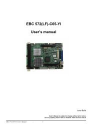
Locations of the Jumpers and <strong>Connectors</strong><br />
The figure below is the main board which is the board used in the nROK3000 system. It shows the locations of the jumpers and connectors.<br />
Copyright © 2012 <strong>NEXCOM</strong> International Co., Ltd. All rights reserved 12<br />
nROK 3000 User Manual
Chapter 2: Jumpers and <strong>Connectors</strong><br />
Jumper Settings<br />
(*) for default seeting<br />
IGNITION Select (JP7)<br />
Pin No. Status Function Description<br />
1-2 Short IGNITION<br />
2-3(*) Short* +12V<br />
NOTE: Only nROK3000-A supports ignition function<br />
IGNITION Select ( JP8) (default NC)<br />
Pin No. Status Function Description<br />
1-2 Short IGNITION<br />
2-3 Short +12V<br />
CMOS Input Voltage Select (J3)<br />
Pin No. Status Function Description<br />
1-2(*) Short* VBAT IN<br />
2-3 Short Clear CMOS<br />
TEMP SENSOR (JP5)<br />
Pin No. Function Description<br />
1 SENSOR+<br />
2 GND<br />
PCI104 VI/O Select Voltage (J9 )<br />
Pin No. Status Function Description<br />
1-4(*) Short* +3.3V<br />
3-6 Short +5V<br />
MCU Download (JP4)<br />
Pin Function Description<br />
1 +V3.3ALW<br />
2 C2D<br />
3 MRST<br />
4 C2CK<br />
5 GND<br />
6 WP<br />
7 SI<br />
8 GND<br />
GAL Download (JP2)<br />
Pin Function Description<br />
1 +V3.3S<br />
2 GND<br />
3 TCK<br />
4 TDO<br />
5 TDI<br />
6 TMS<br />
MCU COM PORT (JP6)<br />
Pin No. Status Function Description<br />
1 TX +3.3V<br />
2 RX +5V<br />
3 GND<br />
Copyright © 2012 <strong>NEXCOM</strong> International Co., Ltd. All rights reserved 13<br />
nROK 3000 User Manual
Chapter 2: Jumpers and <strong>Connectors</strong><br />
<strong>Connectors</strong><br />
UART CONNECTOR (RS232/422/485&GPIO) (CN1)<br />
A. Connector size:2 x 15 = 30Pins PIN Header, ( 1.0 mm Pitch )<br />
B. Connector location:<br />
Connector pin definition<br />
Pin Definition Pin Definition<br />
1 RS422_RX+_A 2 SP_TXD_1<br />
3 RS422_RX-_A 4 SP_RI_1<br />
5 RS422_TX+_A 6 SP_DTR_1<br />
7 RS422_TX-_A 8 SP_CTS_1<br />
9 RS485_TX+_A 10 SP_DCD_1<br />
11 RS485_TX-_A 12 SP_RTS_1<br />
13 RS4852_TX+_A 14 SP_RXD_1<br />
15 RS4852_TX-_A 16 SP_DSR_1<br />
17 NC 18 NC<br />
19 NC 20 NC<br />
21 ISO1_GND 22 ISO1_GND<br />
23 G_I_1 24 G_O_1<br />
25 G_I_2 26 G_O_2<br />
27 G_I_3 28 G_O_3<br />
29 G_I_4 30 G_O_4<br />
DVI+VGA CONNECTOR (CN2)<br />
A. Connector size:2 x 15 = 30Pins PIN Header, ( 1.0 mm Pitch )<br />
B. Connector location:<br />
Connector pin definition<br />
Pin Definition Pin Definition<br />
1 CH_CLK_N 2 DVI_I_5V<br />
3 CH_CLK_P 4 HPDET_I<br />
5 CH_TX0_N 6 DVI_I_DDC_D_R<br />
7 CH_TX0_P 8 DVI_I_DDC_C_R<br />
9 CH_TX1_N 10 CH_GND<br />
11 CH_TX1_P 12 CH_GND<br />
13 CH_TX2_N 14 CH_GND<br />
15 CH_TX2_P 16 CH_GND<br />
17 NC 18 NC<br />
19 NC 20 NC<br />
21 CH_GND 22 VGA1_HSYNC<br />
23 VGA1_RED 24 VGA1_VSYNC<br />
25 VGA1_BLUE 26 VGA1_DDCDAT<br />
27 VGA1_GREEN 28 VGA1_DDCCLK<br />
29 M_DET 30 VGA1_PWR_L<br />
Copyright © 2012 <strong>NEXCOM</strong> International Co., Ltd. All rights reserved 14<br />
nROK 3000 User Manual
Chapter 2: Jumpers and <strong>Connectors</strong><br />
<strong>Connectors</strong><br />
GPS Connector COM6 (J4)<br />
Connector pin definition<br />
Pin Definition Pin Definition<br />
1 GPS_BAT 2 GPS_LED#<br />
3 SP_TX1 4 SP_RX1<br />
5 GND 6 VCC3_3S<br />
AUDIO CONNECTOR (J11)<br />
A. Connector size: 1 x 6 = 6 Pins PIN Header, ( 1.0 mm Pitch )<br />
B. Connector location:<br />
Connector pin definition<br />
Pin Definition Pin Definition<br />
1 SURR_OUT_L_CA 2 SURR_JD<br />
3 SURR_OUT_R_CA 4 MIC_OUT-R<br />
5 MIC_JD 6 C_GND<br />
Copyright © 2012 <strong>NEXCOM</strong> International Co., Ltd. All rights reserved 15<br />
nROK 3000 User Manual
Chapter 2: Jumpers and <strong>Connectors</strong><br />
<strong>Connectors</strong><br />
GAL Programmer PIN Header (JP2)<br />
Connector pin definition<br />
Pin Definition Pin Definition<br />
1 VCC3_3 2 GND<br />
3 TCK 4 TDO<br />
5 TDI 6 TMS<br />
MCU Programmer PIN Header (JP4)<br />
A. Connector size: 1 x 6 = 6 Pins PIN Header, ( 1.0 mm Pitch )<br />
B. Connector location:<br />
Connector pin definition<br />
Pin Definition Pin Definition<br />
1 +3.3ALW 2 C2D<br />
3 MRST 4 C2CK<br />
5 GND<br />
Copyright © 2012 <strong>NEXCOM</strong> International Co., Ltd. All rights reserved 16<br />
nROK 3000 User Manual
Chapter 2: Jumpers and <strong>Connectors</strong><br />
<strong>Connectors</strong><br />
LAN connector (J5)(J7)(J8)<br />
A. Connector size: M12<br />
B. Connector location<br />
Connector pin definition<br />
Pin Definition Pin Definition<br />
1 LAN_MDI_0P_R 2 LAN_MDI_0N_R<br />
3 LAN_MDI_1P_R 4 LAN_MDI_1N_R<br />
FRONT USB connector (J10)<br />
A. Connector size: M12<br />
B. Connector location<br />
Connector pin definition<br />
Pin Definition Pin Definition<br />
1 USB_0N 2 USB_0P<br />
3 USB_VCC0 4 UGND_1<br />
Copyright © 2012 <strong>NEXCOM</strong> International Co., Ltd. All rights reserved 17<br />
nROK 3000 User Manual
Chapter 2: Jumpers and <strong>Connectors</strong><br />
<strong>Connectors</strong><br />
REAR USB connector (USB1)<br />
Connector location:<br />
Connector pin definition<br />
Pin Definition Pin Definition<br />
1 VCC 2 DATA1-<br />
3 DATA1+ 4 GND<br />
5 VCC 6 DATA-<br />
7 DATA+ 8 GND<br />
PCI-104 VI/O voltage setting (J9)<br />
A. Connector size: M12<br />
B. Connector location<br />
Connector pin definition<br />
Pin No. Status Function Description<br />
(1-3)(2-4) (*) Short +3.3V<br />
(3-5)(4-6) Short +5V<br />
Copyright © 2012 <strong>NEXCOM</strong> International Co., Ltd. All rights reserved 18<br />
nROK 3000 User Manual
Chapter 2: Jumpers and <strong>Connectors</strong><br />
<strong>Connectors</strong><br />
PCI-104 connector (CN21)<br />
Connector pin definition<br />
Pin A B C D<br />
1 GND Reserved +5 AD0O<br />
2 VI/O AD02 AD01 +5V<br />
3 AD05 GND AD04 AD03<br />
4 C/BE0# AD07 GND AD06<br />
5 GNDA AD09 AD08 GND<br />
6 AD11 VI/O AD10 M66EN<br />
7 AD14 AD13 GND AD12<br />
8 +3.3V C/BE1# AD15 +3.3V<br />
9 SERR3 GND Reserved PAR<br />
10 GND PERR# +3.3V Reserved<br />
11 STOP# +3.3V LOCK# GND<br />
12 +3.3V TRDY# GND DEVSEL#<br />
13 FRAME# GND IRDY# +3.3V<br />
14 GND AD16 +3.3V C/BE2#<br />
15 AD18 +3.3V AD17 GND<br />
Pin A B C D<br />
16 AD21 AD20 GND AD19<br />
17 +3.3V AD23 AD22 +3.3V<br />
18 IDSEL0 GND IDSEL1 IDSEL2<br />
19 AD24 C/BE3# VI/O IDSEL3<br />
20 GND AD26 AD25 GND<br />
21 AD29 +5V AD28 AD27<br />
22 +5V AD30 GND AD31<br />
23 REQ0# GND REQ1# VI/O<br />
24 GND REQ2# +5V GNT0#<br />
25 GNT1# VI/O GNT2# GND<br />
26 +5V CLK0 GND CLK1<br />
27 CLK2 +5V CLK3 GND<br />
28 GND INTD# +5V RST#<br />
29 +12V INTA# INTB# INTC#<br />
30 +12V REQ3# GNT3# GND<br />
Copyright © 2012 <strong>NEXCOM</strong> International Co., Ltd. All rights reserved 19<br />
nROK 3000 User Manual
Chapter 2: Jumpers and <strong>Connectors</strong><br />
<strong>Connectors</strong><br />
RESET BUTTON (SW2)<br />
Connector pin definition<br />
Pin Function Description<br />
1 GND<br />
2 RST_BTN#<br />
MCU COM PORT (JP6)<br />
Connector pin definition<br />
Pin Function Description<br />
1 TX<br />
2 RX<br />
3 GND<br />
Copyright © 2012 <strong>NEXCOM</strong> International Co., Ltd. All rights reserved 20<br />
nROK 3000 User Manual
Chapter 2: Jumpers and <strong>Connectors</strong><br />
<strong>Connectors</strong><br />
TEMP SENSOR (JP5)<br />
Connector pin definition<br />
Pin Function Description<br />
1 SENSOR+<br />
2 GND<br />
POWER INPUT<br />
+12V DC Power Input Connector (CON1)<br />
Connector pin definition<br />
Pin Function Description<br />
1 +12v<br />
2 +12v<br />
3 GND<br />
4. GND<br />
5. GND<br />
6. Ignition<br />
Copyright © 2012 <strong>NEXCOM</strong> International Co., Ltd. All rights reserved 21<br />
nROK 3000 User Manual
Chapter 2: Jumpers and <strong>Connectors</strong><br />
<strong>Connectors</strong><br />
12VSD DC Power Input Connector (CON2)<br />
Connector pin definition<br />
Pin Function Description<br />
1 12VSD<br />
2 GND<br />
12VSD GPIO (J6)<br />
Connector pin definition<br />
Pin Function Description<br />
1 3VSB<br />
2 GND<br />
Copyright © 2012 <strong>NEXCOM</strong> International Co., Ltd. All rights reserved 22<br />
nROK 3000 User Manual
Chapter 2: Jumpers and <strong>Connectors</strong><br />
<strong>Connectors</strong><br />
POWER ON ,HD ,WWAN ,WLAN Active LED (LED1)<br />
Connector pin definition<br />
Pin Function Description<br />
1 POWER LED<br />
2 HD LED<br />
3 WWAN LED<br />
4 WLAN LED<br />
Serial-ATA (CN3)<br />
Connector pin definition<br />
Pin Definition Pin Definition<br />
1 GND 2 SATA_TXP0 -<br />
3 SATA_TXN0 4 GND<br />
5 SATA_RXN0 6 SATA_RXP0<br />
7 GND<br />
Copyright © 2012 <strong>NEXCOM</strong> International Co., Ltd. All rights reserved 23<br />
nROK 3000 User Manual
Chapter 2: Jumpers and <strong>Connectors</strong><br />
<strong>Connectors</strong><br />
Serial-ATA POWER INPUT (J1)<br />
Connector pin definition<br />
Pin Definition Pin Definition<br />
1 12V 2 GND<br />
3 GND 4 VCC5<br />
Mini-PCIe (3.5G)(CN6)<br />
Connector pin definition<br />
Pin Definition Pin Definition Pin Definition Pin Definition<br />
1 MIC + 2 +V3.3S 27 GND 28 NC<br />
3 MIC - 4 GND 29 GND 30 NC<br />
5 SPK + 6 NC 31 NC 32 NC<br />
7 GND 8 USIM PWR 33 RESET 34 GND<br />
9 GND 10 USIM DATa 35 GND 36 USB_D-<br />
Copyright © 2012 <strong>NEXCOM</strong> International Co., Ltd. All rights reserved 24<br />
nROK 3000 User Manual<br />
11<br />
VCC_<br />
MSM26_DIG<br />
12 USIM CLK 37 GND 38 USB_D+<br />
13 NC 14 USIM RST 39 +V3.3S 40 GND<br />
15 GND 16 NC 41 +V3.3S 42 LED_WWAN#<br />
17 NC 18 GND 43 GND 44 NC<br />
19 NC 20 W_DISABLE# 45 NC 46 NC<br />
21 GND 22 NC 47 NC 48 NC<br />
23 NC 24 NC 49 NC 50 GND<br />
25 NC 26 GND 51 NC 52 +V3.3S
Chapter 2: Jumpers and <strong>Connectors</strong><br />
<strong>Connectors</strong><br />
Mini-PCIe (WLAN)(CN7)<br />
Connector pin definition<br />
Pin Definition Pin Definition Pin Definition Pin Definition<br />
1 WAKE# 2 +V3.3S 27 GND 28 +V1.5S<br />
3 NC 4 GND 29 GND 30 SMB_CLK<br />
5 NC 6 +V1.5S 31 PETn0 32 SMB_DATA<br />
7 CLKREQ# 8 NC 33 PETp0 34 GND<br />
9 GND 10 NC 35 GND 36 USB_D-<br />
11 REFCLK- 12 NC 37 NC 38 USB_D+<br />
13 REFCLK+ 14 NC 39 NC 40 GND<br />
15 GND 16 NC 41 NC 42 LED_WWAN#<br />
17 NC 18 GND 43 NC 44 LED_WLAN#<br />
19 NC 20 DISABLE# 45 NC 46 LED_WPAN#<br />
21 GND 22 PERST# 47 NC 48 +V1.5S<br />
23 PERn0 24 +3.3S 49 NC 50 GND<br />
25 PERp0 26 GND 51 NC 52 +V3.3S<br />
SIM CARD CONNECTOR (CN4) (CN5)<br />
Connector pin definition<br />
Pin Definition Pin Definition<br />
C1 POWER VOLTAGE C2 RESET SIGNAL<br />
C3 CLOCK SIGNAL C5 GND<br />
C6 VPP:PROGRAM VOLTAGE C7 I/O<br />
SW Contact present switch<br />
Copyright © 2012 <strong>NEXCOM</strong> International Co., Ltd. All rights reserved 25<br />
nROK 3000 User Manual
Chapter 3: System Setup<br />
ChaPter 3: system setuP<br />
Removing the Chassis Cover<br />
CAUTION!<br />
Prior to removing the chassis cover, make sure the unit’s power is off and disconnected from the power sources to prevent electric shock or<br />
system damage.<br />
1. The screws on the chassis are used to secure the cover to the chassis. Remove these screws and put them in a safe place for later use<br />
Front View<br />
Rear View<br />
Base View<br />
Copyright © 2012 <strong>NEXCOM</strong> International Co., Ltd. All rights reserved 26<br />
nROK 3000 User Manual
Chapter 3: System Setup<br />
Removing the Chassis Cover<br />
2. Lift the cover upward then remove it from the chassis.<br />
Copyright © 2012 <strong>NEXCOM</strong> International Co., Ltd. All rights reserved 27<br />
nROK 3000 User Manual
Chapter 3: System Setup<br />
Installing the Wi-Fi and GPRS/UMTS/HSDPA Modules<br />
1. Remove the screws and SSD tray.<br />
2. The Mini PCI Express slot shown below is used to install a Wi-Fi, 3.5G<br />
commu-nication module such as GPRS, UMTS or HSDPA module.<br />
WWAN<br />
Mini PCI<br />
Express slot<br />
Wi-Fi<br />
Mini PCI<br />
Express slot<br />
3. Insert the module into the Mini PCI Express slot at a 45 degrees angle<br />
until the gold-plated connector on the edge of the module completely<br />
disappears inside the slot.<br />
4. Push the module down then secure it with mounting screws.<br />
5. Attach one end of the RF cable onto the module<br />
Copyright © 2012 <strong>NEXCOM</strong> International Co., Ltd. All rights reserved 28<br />
nROK 3000 User Manual
Chapter 3: System Setup<br />
Installing SSD Drive<br />
1. Remove the SSD drive tray.<br />
2. Place the SDD drive into the tray and then tighten the four screws.<br />
Copyright © 2012 <strong>NEXCOM</strong> International Co., Ltd. All rights reserved 29<br />
nROK 3000 User Manual
Chapter 3: System Setup<br />
Installing SSD Drive<br />
3. Installing the HDD tray, and then tighten the screws to secure the drive<br />
to the chassis.<br />
Copyright © 2012 <strong>NEXCOM</strong> International Co., Ltd. All rights reserved 30<br />
nROK 3000 User Manual
Chapter 3: System Setup<br />
Rackmount Brackets<br />
The rackmount brackets provide a convenient and economical way of mounting the system on the wall.<br />
1. The mounting holes are located at the bottom of the system. Secure the<br />
brackets on each side of the system using the provided mounting screws.<br />
Rackmount bracket<br />
Secure the bracket<br />
to the system<br />
2. Now mount the system on the wall by fastening screws through the<br />
bracket’s mounting holes.<br />
Fasten screws to<br />
mount the system<br />
to the wall<br />
Copyright © 2012 <strong>NEXCOM</strong> International Co., Ltd. All rights reserved 31<br />
nROK 3000 User Manual
Appendix A: I/O Address Function<br />
aPPendIx a: I/o address funCtIon<br />
I/O Address Function<br />
(*) for default setting<br />
GPIO LED / UMTS LED / Ignition Status<br />
I/O port : 0EE0H<br />
Bit Function Description<br />
Bit 0 GPIO LED<br />
0: OFF (*)<br />
1: ON<br />
Bit 1 UMTS LED<br />
0: LED for Wireless (*)<br />
1: LED for 3.5G and Wireless<br />
GPIO<br />
I/O port : 0EE4H<br />
Bit Function Description<br />
Bit 0-3 GPO 1-4<br />
Bit 4-7 GPI 1-4<br />
Copyright © 2012 <strong>NEXCOM</strong> International Co., Ltd. All rights reserved 32<br />
nROK 3000 User Manual
Appendix A: I/O Address Function<br />
WDT<br />
I/O port : 0EE5H<br />
Bit Function Description<br />
Bit 3 WDT Disable/Enable<br />
0: Disable (*)<br />
1: Enable<br />
Bit 2, 1, 0: Time Setting<br />
Bit 2~0 Time (sec)<br />
000 1 (*)<br />
001 2<br />
010 4<br />
011 8<br />
100 16<br />
101 32<br />
110 64<br />
111 128<br />
Auto clear WDT timer when reading/writing I/O port 0EE5H.<br />
Onboard Module Disable/Enable(1)<br />
I/O port : 0EE6H<br />
Bit Function Description<br />
Bit 0 3.5G module<br />
0: Disable<br />
1: Enable (*)<br />
Bit 1 WLAN module<br />
0: Disable<br />
1: Enable (*)<br />
Copyright © 2012 <strong>NEXCOM</strong> International Co., Ltd. All rights reserved 33<br />
nROK 3000 User Manual
Appendix A: I/O Address Function<br />
Delay Time Setting<br />
I/O port : 0EE7H<br />
Bit7 Power On Delay<br />
0 Disable(*)<br />
1 Enable<br />
Bit6 Power Off Delay<br />
0 Disable(*)<br />
1 Enable<br />
Delay On Time Setting<br />
Bit3~5 Function Description<br />
000 10 sec<br />
001 30 sec<br />
010 1 min<br />
011 5 min<br />
100 10 min<br />
101 15 min<br />
110 30 min<br />
111 1 hour<br />
Delay Off Time Setting<br />
Bit 2~0 Time (sec)<br />
000 20 sec<br />
001 1 min<br />
010 5 min<br />
011 10 min<br />
100 30 min<br />
101 1 hour<br />
110 6 hour<br />
111 18 hour<br />
Copyright © 2012 <strong>NEXCOM</strong> International Co., Ltd. All rights reserved 34<br />
nROK 3000 User Manual
Appendix A: I/O Address Function<br />
Setup Command<br />
I/O port : 0EE9H<br />
Restart the Setup Command<br />
Enable byte<br />
AA<br />
Using end byte to tell the data flow end<br />
Data End byte<br />
(Delay time)(Startup/Shutdown voltage setting) 55<br />
Onboard Module Disable/Enable(1)<br />
I/O port : 0EEAH<br />
Enable byte<br />
GAL Download control<br />
I/O port : 0EEBH<br />
Restart the Setup Command<br />
Enable byte<br />
Copyright © 2012 <strong>NEXCOM</strong> International Co., Ltd. All rights reserved 35<br />
nROK 3000 User Manual<br />
AA<br />
AA
Appendix B: Power Consumption<br />
aPPendIx B: Power ConsumPtIon<br />
Power Consumption<br />
Test Equipment/Tool<br />
DUT#1 : nROK3000 with SSD<br />
DUT#2 : nROK3000 with SSD and 3.5G module<br />
Windows XP<br />
Burn-in Software: Version 5.0<br />
Test Condition<br />
Room temperature<br />
Power supply graduation: 12V 5A<br />
Test Procedure:<br />
1. Start of all function at DUT and measure power consumption.<br />
2. Get system into suspend mode and measure power consumption.<br />
* Device: N/A<br />
Unit Idle Mode 100% Burn-in Mode S3 S4 S5<br />
DUT#1 1.03A 1.18A 90mA 10mA 10mA<br />
DUT#2 1.13A 1.24A 140mA 50mA 50mA<br />
Copyright © 2012 <strong>NEXCOM</strong> International Co., Ltd. All rights reserved 36<br />
nROK 3000 User Manual