IP Wireless / Wired Camera - Agasio POE & Wireless IP Cameras
IP Wireless / Wired Camera - Agasio POE & Wireless IP Cameras
IP Wireless / Wired Camera - Agasio POE & Wireless IP Cameras

Create successful ePaper yourself
Turn your PDF publications into a flip-book with our unique Google optimized e-Paper software.
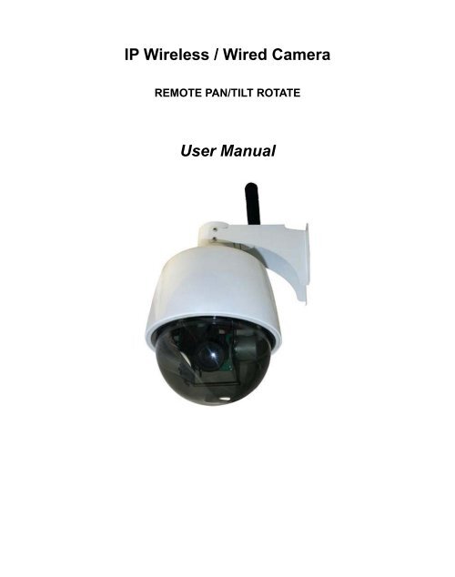
<strong>IP</strong> <strong>Wireless</strong> / <strong>Wired</strong> <strong>Camera</strong><br />
REMOTE PAN/TILT ROTATE<br />
User Manual
More Security, More Convenience<br />
CONTENTS<br />
1 WELCOME ......................................................................................................................................................3<br />
1.1 FEATURES................................................................................................................................................................................................ 3<br />
1.2 PACKING LIST.......................................................................................................................................................................................... 3<br />
1.3 PRODUCT VIEWS ..................................................................................................................................................................................... 4<br />
1.4 PC SYSTEM REQUIREMENTS ................................................................................................................................................................... 5<br />
1.5 HARDWARE INSTRUCTION ....................................................................................................................................................................... 5<br />
1.6 SOFTWARE INSTALLATION ....................................................................................................................................................................... 5<br />
2. SOFTWARE OPERATION..............................................................................................................................7<br />
2.1 <strong>IP</strong> CAMERA TOOL .................................................................................................................................................................................... 7<br />
2.2 CAMERA LOGIN..................................................................................................................................................................................... 10<br />
2.3 FOR IE BROWSER .................................................................................................................................................................................. 12<br />
2.4 FOR SAFARI, FIREFOX, GOOGLE BROWSER ........................................................................................................................................... 14<br />
2.5 FOR MOBILE PHONE.............................................................................................................................................................................. 15<br />
2.6 ACTIVEX MODE (FOR IE BROWSER)..................................................................................................................................................... 15<br />
2.7 FOR VISITOR.......................................................................................................................................................................................... 15<br />
2.8 FOR OPERATOR...................................................................................................................................................................................... 19<br />
2.9 FOR ADMINISTRATOR ............................................................................................................................................................................ 21<br />
3 SETTINGS AS ADMINISTRATOR ................................................................................................................21<br />
3.1 MULTI-DEVICE SETTINGS...................................................................................................................................................................... 22<br />
3.2 NETWORK SETTINGS ............................................................................................................................................................................. 27<br />
3.3 BASIC NETWORK SETTINGS................................................................................................................................................................... 27<br />
3.4 WIRELESS LAN SETTINGS...................................................................................................................................................................... 29<br />
3.5 ADSL SETTINGS.................................................................................................................................................................................... 31<br />
3.6 UPNP SETTINGS .................................................................................................................................................................................... 31<br />
3.7 DDNS SERVICE SETTINGS..................................................................................................................................................................... 31<br />
3.8 SYSTEM SETTINGS................................................................................................................................................................................. 35<br />
3.9 ALIAS SETTINGS.................................................................................................................................................................................... 36<br />
3.10 DATE &TIME SETTINGS....................................................................................................................................................................... 36<br />
3.11 USERS SETTINGS ................................................................................................................................................................................. 37<br />
3.12 PTZ SETTINGS..................................................................................................................................................................................... 38<br />
3.13 INDICATOR SETTINGS .......................................................................................................................................................................... 38<br />
3.14 BACKUP & RESTORE ........................................................................................................................................................................... 38<br />
3.15 OTHER SETTINGS................................................................................................................................................................................. 40<br />
3.16 MAIL SERVICE SETTINGS..................................................................................................................................................................... 40<br />
3.17 FTP SERVICE SETTINGS....................................................................................................................................................................... 42<br />
3.18 ALARM SERVICE SETTINGS.................................................................................................................................................................. 43<br />
3.19 SEND MAIL ON ALARM........................................................................................................................................................................ 46<br />
3.20 PATH SETTINGS.................................................................................................................................................................................... 48<br />
3.21 SERVER PUSH MODE (FOR SAFARI, FIREFOX, GOOGLE BROWSER) ..................................................................................................... 49<br />
3.22 SIGN IN MOBILE PHONE........................................................................................................................................................................ 49<br />
4. APPENDIX....................................................................................................................................................50<br />
4.1 FREQUENTLY ASKED QUESTIONS .......................................................................................................................................................... 50<br />
4.2 DEFAULT PARAMETERS.......................................................................................................................................................................... 53<br />
5. SPECIFICATIONS ........................................................................................................................................53<br />
6. OBTAINING TECHNICAL SUPPORT..........................................................................................................54<br />
2
1 WELCOME<br />
More Security, More Convenience<br />
This is an integrated wireless <strong>IP</strong> <strong>Camera</strong> solution. It combines a high quality digital Video <strong>Camera</strong> with network<br />
connectivity and a powerful web server to bring clear to your Desktop from anywhere on your local network or<br />
over the Internet.<br />
The basic function of it is transmitting remote video on <strong>IP</strong> network. The high quality video image can be<br />
transmitted with 30fps speed on the LAN/WAN by using MJPEG hardware compression technology.<br />
It is based on TCP/<strong>IP</strong> standard, build-in WEB server which could support Internet Explorer. Therefore the<br />
management and maintenance of your device become easier by using network to achieve the remote<br />
configuration, start-up and upgrade firmware.<br />
You can use this <strong>IP</strong> <strong>Camera</strong> to monitor some special places such as your home and your office. Also<br />
controlling and managing images are easy by clicking the website through the network.<br />
1.1 Features<br />
☆Powerful high-speed video protocol processor<br />
☆High-sensitivity 1/4’’ CMOS sensor<br />
☆Picture total 300k pixels<br />
☆Support 3x Optical Zoom<br />
☆Support PT control, Pan 355°, Tilt 90°<br />
☆Optimize MJPEG video compression for transmission<br />
☆Multi-level users’ management and passwords definition<br />
☆Embed Web Server for users to visit by IE<br />
☆Support wireless network (WI-FI/802.11/b/g)<br />
☆Support Dynamic <strong>IP</strong> (DDNS) and UPNP LAN and Internet (ADSL, Cable Modem)<br />
☆Give alarm in cause of motion detection<br />
☆Support image snapshot<br />
☆Support multiple protocols:HTTP/TCP/<strong>IP</strong>/UDP/SMTP/DDNS/SNTP/DHCP/FTP<br />
☆Support WEP/WPA/WPA2 encryption<br />
☆Support 3G phone, Smart phone control and surveillance<br />
☆Support Firefox, Safari, Google chrome browser.<br />
1.2 Packing List<br />
Untie the pack and check the items contained against the following list:<br />
●<strong>IP</strong> <strong>Camera</strong> X1<br />
●Wi-Fi Antenna X1 (only available for wireless model)<br />
●User Manual X1<br />
●DC Power Supply X1<br />
●CD X1<br />
●Network Cable X1<br />
●Mounting bracket X1<br />
NOTE: Please contact us immediately if anything damaged or short of contents.<br />
3
1.3 Product Views<br />
1.3.1 Front View<br />
More Security, More Convenience<br />
Figure 1.1<br />
1 LENS: CMOS sensor with fixed zoom lens.<br />
2 Housing: Alloy housing for waterproof<br />
3 <strong>Wireless</strong> Antenna: WI-FI Antenna (For wireless model only)<br />
1.3.2 Cable Interface<br />
Figure 1.2<br />
Audio Output: The jack is used to plug external speaker or audio output device.<br />
Audio Input: The jack is used to plug external microphone or audio input device.<br />
I/O Alarm Pin: 1 Alarm input(GND) 2 Input 3 Output A 4 Output B<br />
Network Interface: RJ-45/10-100 base T<br />
Network Light: The green LED will on when network connected, the yellow LED will blink when data<br />
transferred<br />
Reset: Press and hold the RESET button for about 15 seconds, all the parameters will be back to the factory<br />
default settings. (Please keep the power on when do RESET)<br />
Power: DC 12V/2A power supply<br />
4
1.4 PC System Requirements<br />
More Security, More Convenience<br />
System configuration requirements :( Example for viewing four <strong>IP</strong>CAM)<br />
CPU: 2.06GHZ or above<br />
Memory: 256M or above<br />
Network Card: 10M or above<br />
Display Card: 64M or above memory<br />
Recommendable Operating system: Windows 2000/ XP/ Vista/ 7<br />
1.5 Hardware Instruction<br />
Follow the steps below to set up your camera hardware. Make sure to follow each step carefully to ensure that<br />
the camera operates properly<br />
1. Install the Wi-Fi antenna(For wireless model)<br />
2. Plug the power adaptor into camera<br />
3. Plug the network cable into camera and router/switch<br />
4. It takes approx 30 seconds to boot up the camera, then you will find the <strong>IP</strong> address from<br />
“<strong>IP</strong> <strong>Camera</strong> Tool” (Figure: 1.8)<br />
5. When the power on and network cable connected, the green led of the real panel will keep on,<br />
The yellow led will keep flash.<br />
1.6 Software Installation<br />
Figure1.3<br />
Attention: In order to make the installation correctly, we suggest that turn off your Firewall and Antivirus before<br />
install the ActiveX, Don’t worry, it is safe. (If you are Windows 7 User, please run as administrator)<br />
Software installation is the key to the successful use of this product.<br />
Install the follow software:<br />
1. <strong>IP</strong> <strong>Camera</strong> Tool: Open the CD, dbclick “<strong>IP</strong>CamSetup.exe”, only click next, you will complete the software<br />
installation.(figure1.5/ 1.6/ 1.7)<br />
2. ActiveX: Double click “Appinstall.exe”—“Next”—“Install”—“Finish”.<br />
Figure1.4<br />
5
More Security, More Convenience<br />
Figure1.5<br />
Figure1.6<br />
Figure1.7<br />
After this done, the icon “<strong>IP</strong> <strong>Camera</strong> Tool” will be displayed on desktop automatically.<br />
6
More Security, More Convenience<br />
CAUTION: Before installing and using the product, please read the following precautions carefully and make<br />
sure they are fully understood.<br />
Use only the power adaptor attached with the product. Use unauthorized power adapter may cause damage to<br />
your <strong>IP</strong> <strong>Camera</strong>.<br />
Do not touch the lens of the <strong>IP</strong> <strong>Camera</strong> at will. The optimum focus range has been set before it is delivered out<br />
of the factory. If you turn the lens, it may cause incorrect focus and vague images.<br />
Do not turn the Pan/Tilt by force, it may cause damage to internal components of the Pan/Tilt.<br />
For firmware upgrading or connection with an external, refer to detailed instructions contained in the CD.<br />
2. SOFTWARE OPERATION<br />
2.1 <strong>IP</strong> <strong>Camera</strong> Tool<br />
When the Device has been mounted properly, you can double click the Icon “<strong>IP</strong> <strong>Camera</strong> Tool”<br />
and a dialog box as Figure 1.8 will pop up.<br />
Figure1.8<br />
Note: The software searches <strong>IP</strong> Servers automatically over LAN.<br />
There are 3 cases:<br />
1. No <strong>IP</strong> <strong>Camera</strong>s found within LAN. After about 1 minute search, the Result Field will show “not found <strong>IP</strong><br />
Server” and the program shut automatically.<br />
2. <strong>IP</strong> <strong>Camera</strong>s have been installed within LAN. All the <strong>IP</strong> <strong>Camera</strong>s will be listed and the total number is<br />
displayed in the result field as shown in Figure 1.8<br />
3. The <strong>IP</strong> <strong>Camera</strong>s installed within LAN do not share the same subnet with the monitoring PC. A prompt as<br />
shown in result field (prompt: Subnet doesn’t match, double click to change!). Click the left mouse button to<br />
choose the prompt and click the right mouse, choose Network Configuration to set the static <strong>IP</strong> address of<br />
the <strong>Camera</strong> to the same subnet as LAN. (Figure 2.2)<br />
7
More Security, More Convenience<br />
NOTE: If it shows” Subnet doesn’t match, double click to change!”, you can also choose ”Obtain <strong>IP</strong> from<br />
DHCP Server” to get a dynamic <strong>IP</strong>. (Figure 2.1)<br />
2.1.1 Six Options<br />
Choose the <strong>IP</strong> <strong>Camera</strong> list and Click right mouse, there are six options: (Figure 1.9)<br />
Basic Properties, Network Configuration, Upgrade Firmware,<br />
Refresh <strong>Camera</strong> List, Flush Arp Buffer, About <strong>IP</strong> <strong>Camera</strong> Tool.<br />
2.1.1 .1 Basic Properties<br />
Figure1.9<br />
There are some device information in the Basic Properties, such as Device ID, System Firmware Version,<br />
Web UI Version.(Figure 2.0)<br />
The Device ID just is the camera’s MAC ID, which should be the same as showed on the sticker at the bottom<br />
of camera. Every camera has its unique MAC ID. So if there are many <strong>IP</strong> address showed in the list, check the<br />
MAC ID, you can ensure which camera is it.<br />
Sometimes, if there is no <strong>IP</strong> address showed on the <strong>IP</strong> <strong>Camera</strong> tool, maybe it’s blocked by firewall, then add<br />
the MAC ID to the router, and give it a fixed <strong>IP</strong> or add the MAC ID as a trusted site. There are two MAC<br />
Address, one is Device MAC ID, the other is WIFI MAC ID.<br />
WIFI MAC ID, you can find it from the sticker at the bottom of the camera, if this sticker lost, you can login your<br />
WIFI router, check the host status, which will show all the WIFI device connect to this router, you can also find<br />
the <strong>IP</strong>CAM’s WIFI MAC ID there.<br />
Figure2.0<br />
8
2.1.1.2 Network Configuration<br />
More Security, More Convenience<br />
In this page, you can configure the Network parameter.<br />
Figure2.1<br />
Obtain <strong>IP</strong> from DHCP server: If clicked, the device will obtain <strong>IP</strong> from DHCP server. In other words, the<br />
camera will have a dynamic <strong>IP</strong>. (Make sure the Router which the camera connects has DHCP function and<br />
DHCP is enabled). (Figure 2.1)<br />
Figure 2.2<br />
<strong>IP</strong> address: Fill in the <strong>IP</strong> address assigned and make sure it is in the same subnet as the Gateway, and the<br />
subnet should be the same as your computer or router. (i.e. the first three sections are the same)<br />
Subnet Mask: The default subnet mask of the equipment is: 255.255.255.0. You can find the subnet mask<br />
from your PC or router.<br />
Gateway: Make sure it is in the same subnet with PC’s <strong>IP</strong> address .Here gateway is the LAN <strong>IP</strong> of your router.<br />
DNS Server: <strong>IP</strong> address of <strong>IP</strong>S network provider. You can also set it’s the same as the Gateway.<br />
NOTE: You can find the Subnet Mask, Gateway, DNS Server from your router, or check the local connection<br />
status of your computer, get all the parameters. Normally two DNS servers are optional.<br />
Http Port: LAN port assigned for the equipment, default is 80. You could set another port number like 81, 801,<br />
8001 etc.<br />
User: Default administrator username is: admin (please make sure all are lowercase letter)<br />
Password: Default password is bank, no password.<br />
NOTE: When prompt “subnet doesn’t match, double chick to change!” appeared, please set the <strong>IP</strong> Address,<br />
Subnet Mask, Gateway, DNS Server once again, or enable Obtain <strong>IP</strong> from DHCP server.<br />
9
2.1.1.3 Upgrade Firmware<br />
More Security, More Convenience<br />
Enter the correct User and Password to upgrade system Firmware and Web UI. If you upgrade the camera,<br />
Please upgrade system firmware first and then upgrade Web UI. Or it may damage the camera.(Figure<br />
2.3)<br />
Figure 2.3<br />
Please download the firmware package under the correct type of your camera before upgrade.<br />
Follow the upgrade document in the package carefully to upgrade. Please look readme firstly before you do<br />
upgrade.<br />
CAUTION: Please don’t upgrade the firmware freely. Sometimes, your camera may be damaged if wrong<br />
operation during upgrade.<br />
If your camera works well with the current firmware, we recommend you’d better not upgrade it.<br />
NOTE: When doing upgrade, please must keep the power on, and the best use wired mode, connect the<br />
network cable.<br />
2.1.1.4 Refresh <strong>Camera</strong> List<br />
Refresh camera list manually.<br />
2.1.1.5 Flush Arp Buffer<br />
When cable network and wireless network of the device are fixed <strong>IP</strong> address .There is a problem you may<br />
encounter is can search the camera <strong>IP</strong> but can’t open the camera web page .you may try to use Flush Arp<br />
Buffer.<br />
2.1.1.6 About <strong>IP</strong> <strong>Camera</strong> Tool<br />
Check the <strong>IP</strong> <strong>Camera</strong> Tool Version and <strong>IP</strong> <strong>Camera</strong> ActiveX Control Version here.<br />
2.2 <strong>Camera</strong> Login<br />
You can access the camera through <strong>IP</strong> <strong>Camera</strong> Tool or IE, Firefox, Safari, Google Chrome or other<br />
standard browser directly.<br />
1. Double click the <strong>IP</strong> address of the <strong>IP</strong> <strong>Camera</strong> listed (Figure 1.8). The default browser you use will run<br />
automatically and come to the camera login interface. (Figure 2.6)<br />
10
More Security, More Convenience<br />
2. To access the camera by IE Browser directly, just type the camera’s <strong>IP</strong> address, for example, if the camera’s<br />
<strong>IP</strong> address is 192.168.1.123:<br />
The default user name is admin, no password<br />
Figure 2.4<br />
Figure 2.5<br />
Input the correct user name and password, the Sign In interface will pop-up.<br />
There are three models to login (figure 2.6).<br />
Figure 2.6<br />
(1) Active Mode (For IE Browser): available in IE6.0 or above explorer<br />
(2) “Server Push Mode”: available in Firefox, Safari, and Google Chrome browser.<br />
(3) “Sign in mobile phone”: available in Mobile phone<br />
11
2.3 For IE Browser<br />
Choose Active Mode (For IE Browser), and sign in.<br />
More Security, More Convenience<br />
Figure 2.7<br />
The first time login the camera, maybe get ActiveX prompt as the picture above, please click the prompt and<br />
choose Run Add-on, refresh and login the camera again, then will see live video, details as below:<br />
Figure2.8<br />
Figure 2.9<br />
12
More Security, More Convenience<br />
Note: If there is still no live video after run ActiveX, and a red cross showed in the center of the screen,<br />
or even just a black screen, please try to enable the ActiveX options of IE security settings.<br />
Please do the follow steps:<br />
1. Close the firewall of your computer.<br />
2. Change the ActiveX settings, “IE” browser > “Tool” > “Internet Options” > “Security”> “Custom Level” ><br />
“ActiveX control and Plug-ins”, all the ActiveX options set to be “Enable”:<br />
Especially:<br />
Enable: Download unsigned ActiveX controls<br />
Enable: Initialize and script ActiveX controls not marked as safe<br />
Enable: Run ActiveX controls and plu-ins<br />
Figure3.0<br />
Figure 3.1<br />
In addition: you can also click “Start” menu->“Internet Explorer”, choose “Internet attributes “ to enter, or via<br />
“Control Panel” ->“Internet Explorer”, enter to Security setting.<br />
If you allowed the ActiveX running, but still could not see live video, only a Red Cross<br />
in the center of<br />
the video, and the device status light change to yellow color , not green, please change another port<br />
13
More Security, More Convenience<br />
number to try. Don’t use port 80, use other port such as 128, 1008 etc.<br />
Figure 3.2<br />
NOTE: Make sure that the firewall or anti-virus software doesn’t block the software or ActiveX. If you couldn’t<br />
see live video, please close your firewall or anti-virus software, and try again.<br />
2.4 For Safari, Firefox, Google Browser<br />
Choose Server Push Mode (For Safari, Firefox, Google Browser), and sign in<br />
Server Push Mode doesn’t support ActiveX, so some functions are not available, such as Play, Stop, Record,<br />
Audio, Talk etc. if you want to use these functions, please use IE browser.<br />
Figure 3.3<br />
14
2.5 For Mobile Phone<br />
More Security, More Convenience<br />
Choose Sign in mobile phone, and sign in.<br />
Mobile phone doesn’t support ActiveX, only some basic functions can be available in this mode.<br />
It supports Iphone, Smart phone, 3G phone etc. Normally, if the mobile phone supports network video, then it<br />
can work with our <strong>IP</strong> <strong>Camera</strong>.<br />
2.6 ActiveX Mode (For IE Browser)<br />
Figure 3.4<br />
Login the camera in ActiveX mode, the main User Interface as below:<br />
NOTE: There are 3 levels of users, Visitor, Operator, Administrator, if you login with different users, the use<br />
authority is different. (See 3.11 User Settings, Figure 8.5)<br />
2.7 For Visitor<br />
When login as Visitor, you can enter the <strong>IP</strong> <strong>Camera</strong> for visitor.<br />
Visitor is the lowest level with only some operation available<br />
15
Channels:<br />
More Security, More Convenience<br />
Figure 3.5<br />
Our IE software supports 9 channels totally. Click can get different windows.<br />
: Click this one, you can view the main channel of the camera you login.<br />
: Click this one; you can view 4 Channels of cameras which connected, from CH1 to CH4.<br />
: Click this one; you can view 9 Channels of cameras which connected, from CH1 to CH9.<br />
NOTE: If you want to view 4/9 channels, you should set the Multi-Device firstly (See 3.1 Multi-Device<br />
Settings)<br />
Status of Channels:<br />
There are 9 icons at the bottom of the UI which show the status of each channel of the camera.<br />
: Grey color, means there is no device connected to the main device from this channel.<br />
: Green color, means the device connected from this channel, and it works well.<br />
: Red color, means the device of this channel is recording.<br />
: Yellow color, means set this channel in multi-device already, but it fails to connect to the main device.<br />
16
OSD Settings:<br />
More Security, More Convenience<br />
� �<br />
Figure 3.6<br />
OSD: Means “On-Screen Display”, click “Audio video” > “OSD”, set display date and time on the video.<br />
Disabled: Click this one, means clear the OSD.<br />
Color: Can set the OSD text color as black, yellow, red, white, blue etc.<br />
Add time stamp on record: Click this, there will be time OSD on record video files.<br />
Figure 3.7<br />
17
Rate and Resolution:<br />
More Security, More Convenience<br />
Rate: Set video frame here, from “full-speed to 1fp/5s”. (Figure 3.8)<br />
Resolution: Set the resolution to be 160*120/ VGA(640*480)/ QVGA (320*240). (Figure 3.9)<br />
NOTE: When doing recording, Rate and Resolution parameter settings is very helpful for getting small<br />
size record files, the lower parameter to get the smaller file.<br />
Figure 3.8 Figure 3.9<br />
TOP Menu:<br />
Figure 4.0<br />
: Click it to get live video. When you want to back to live video from other menus, just click it.<br />
Only under live video, you can do the operation on the right side, such as play, stop, snapshot etc.<br />
: Click it to get into play mode, when you click stop icon, the video will be stopped, then click<br />
play icon, it will show the video again.<br />
: Click it to stop the live video. You can click play icon if you want to see live again.<br />
: Click it to get snapshot. It will show the date and time of the snapshot you get, when you want<br />
to save it, you will find the snapshot file named by “snapshot_MAC ID_date_time”.<br />
: Click it to start record by manual, and the icon will change to red color , click it<br />
again, it will stop record. The record file will be saved to the folder you set. (Figure 10.8-Figure11.0)<br />
: Click it to collect the sound around the camera, if you plug a earphone or a speaker in the<br />
computer which you are using, you will hear the sound around the camera. This <strong>IP</strong> <strong>Camera</strong> has a built-in<br />
microphone, when you click it to start work, the icon will change to red color , click it again, will stop<br />
audio function.<br />
: Click it to start the talk function, firstly you have to plug a microphone in your computer.<br />
When you are talking about something with the microphone from your computer, the sound will come out from<br />
the built-in speaker of the camera, people beside the camera will hear the sound. If you connected an external<br />
speaker from the audio output hole at the back of the camera (Figure 1.2), you will get better sound effect.<br />
Once click it to start work, the icon will change to red color , click it again, will stop talk function.<br />
18
More Security, More Convenience<br />
NOTE: For visitor, if you click other menus which visitor don’t have the right to operate it, there will be a pop-up<br />
of login interface (Figure 2.6), please input the user name / password for at least 3 times to login again.<br />
2.8 For Operator<br />
When login as Operator, you can enter the <strong>IP</strong> <strong>Camera</strong> for Operator.<br />
For operator, it not only supports all the functions which for Visitor, and also supports these functions as below:<br />
Audio Video Settings<br />
Figure 4.1<br />
� �<br />
Figure 4.2<br />
Audio buffer: Click this icon, it will show five numbers, which means 1/2/3/4/5 seconds’ buffer of audio.<br />
19
More Security, More Convenience<br />
Reversal: Click this icon to see the reversal image. Click again, will back to normal.<br />
Mirror: Click this icon to see the mirror image. Click again, will back to normal.<br />
NOTE: You can choose Reversal and Mirror function when you set up the camera in a special position.<br />
Mode, Bright, Contrast Settings<br />
�<br />
Figure 4.3<br />
Mode: This is work mode optional, 50HZ/60HZ for the users who use 50HZ/60HZ frequency, outdoor for the<br />
users who want to use this camera to monitor toward outdoor environment<br />
NOTE: This camera normally should be used in a indoor environment<br />
Bright: Set the parameters to adjust the image quality of video. Click to adjust the value<br />
Contrast: Set the parameters to adjust the image quality of video. Click to adjust the value<br />
Default all: Click it to set all the parameters back to factory setting.<br />
NOTE: If you login the camera, there is no video displayed, and the parameter of bright/contrast is blank,<br />
maybe you can try to click “default all” to set the parameters back to factory setting to get live video.<br />
Pan/Tilt Control<br />
Figure 4.4<br />
: Click this icon, camera will move up, you can click one by one or hold it to control the movement<br />
: Click this icon, camera will move down, you can click one by one or hold it to control the movement<br />
NOTE: It is the same operation as left, right etc.<br />
: Click this icon, the lens will zoom in, and the previous image will become larger, it supports 3Xzoom.<br />
: Click this icon, the lens will zoom out, and the previous image will become smaller<br />
: Click this icon, camera will rotate left and right, means horizontal patrol, click to stop it.<br />
: Click this icon, IO output Switch ON. Click to set it OFF.<br />
20
More Security, More Convenience<br />
RECOMMENDATION:<br />
Image PT function: Image PT function is recommended, you can control the camera direction on the live<br />
video. Double click the right mouse on the live video to enable this function, and you will see a white &<br />
transparent arrow on the live video, click left mouse to control direction, totally eight directions are<br />
available. This is very convenient for Pan/Tilt operation.<br />
Double click right mouse again to exit.<br />
Preset Settings<br />
Figure 4.5<br />
: Set Preset Position. It supports 8 preset positions. Firstly, control the camera rotate to the special<br />
position you need to set, click Set Preset Position button , it will pop-up a dialog frame(Figure 4.5),<br />
choose the any number (1-8) you want to set it be, then it done.<br />
NOTE: Set different positions with a same number, camera will record the last position setting only.<br />
: Call Preset Position. It supports 8 preset positions. If operator wants to monitor an important area quickly<br />
and precisely, just click Call Preset Position button , it will pop-up a dialog frame(Figure 4.5), choose the<br />
number, then camera will rotate to the preset area automatically.<br />
If you want to use Call Preset Position, you have to Set Preset Position firstly.<br />
NOTE: For Operator, if you click other menus which operator don’t have the right to operate it, there will be a<br />
pop-up of login interface (Figure 2.6), please input the user name / password for at least 3 times to login again.<br />
2.9 For Administrator<br />
Details see Settings as Administrator (details3.1-3.22).<br />
.<br />
3 Settings as Administrator<br />
When login as Administrator, you can enter the <strong>IP</strong> <strong>Camera</strong> for Administrator.<br />
Administrator supports all the settings and operations of the camera; you can set and control it freely<br />
There are some special functions only for administrator as below:<br />
21
3.1 Multi-Device Settings<br />
Multi-Device Settings<br />
�<br />
More Security, More Convenience<br />
Figure 4.6<br />
This camera can support max. 9 channels device at the same time.<br />
3.1.1 Set Multi-Device in LAN<br />
In the Multi-Device Settings page, you can see all devices searched in LAN. The 1st device is the default one.<br />
You can add more cameras listed in LAN for monitoring. This web software supports up to 9 <strong>IP</strong> <strong>Camera</strong>s online<br />
simultaneously.<br />
Click The 2nd Device and click the item in the Device List in Lan, it will fill the Alias, Host, Http Port<br />
automatically, then input the correct user name and password, click Add. Set more devices in the same way,<br />
after all done, please click Submit.<br />
22
More Security, More Convenience<br />
Figure 4.7<br />
Click Live Video and then select to see four channels, or click to see nine channels.<br />
Figure 4.8<br />
23
3.1.2 Set Multi-Device for WAN<br />
More Security, More Convenience<br />
Figure 4.9<br />
If you want to view cameras from internet, you have to add these devices by DDNS domain name.<br />
Make sure all these cameras you want to add have been set DDNS successfully. (View 3.7 DDNS Service<br />
Settings) And also these cameras work well with DDNS.<br />
Login the first camera by DDNS domain name and port, this camera will be as the host camera.<br />
Figure 5.0<br />
Click Multi-Device, select Multi-Device Settings. Choose the 2nd Device; fill in the 2nd camera’s Alias, Host,<br />
Http Port, User, Password by manual, click Add. Set more devices in the same way, after all done, please click<br />
24
More Security, More Convenience<br />
Submit.<br />
NOTE: The Alias is optional; you can set the alias as per your wish. The Host must be the camera’s DDNS<br />
domain name, and without “http://”, it’s not the Lan <strong>IP</strong> address.<br />
If you have several cameras, you can use the same DDNS domain name, just set different port number for<br />
each different camera.<br />
Figure 5.1<br />
Note: Add the other camera in the same way, Click submit to add all of them.<br />
25
More Security, More Convenience<br />
Figure 5.2<br />
Click Live Video and then select to see four channels, or to see nine channels.<br />
In this case, you can see all the cameras from a remote position by internet, for example, if you are on the<br />
business trip, you can use the first camera’s (Host camera) DDNS to view all the devices via internet<br />
3.1.3 Upgrade Device Firmware<br />
Figure 5.3<br />
If you want to upgrade the camera, please upgrade Device Firmware first, then upgrade Web UI.<br />
Click Browse and choose correct bin file, then click Submit to do upgrading.<br />
NOTE: Before doing upgrade via Browser, please make sure the <strong>IP</strong> <strong>Camera</strong> Tool of your computer could find<br />
the camera’s <strong>IP</strong>.<br />
Attention: Please must keep the power on during upgrading, and the better use wired mode.<br />
Please don’t try upgrade freely, because wrong operation or incorrect upgrade bin file will damage the camera.<br />
Figure 5.4<br />
26
3.1.4 Restore Factory Settings<br />
More Security, More Convenience<br />
Click Restore Factory Settings, will pop-up a prompt, select OK, all the parameter will be returned to factory<br />
settings, and the device will reboot.<br />
3.1.5 Reboot Device<br />
Figure 5.5<br />
Click Reboot the device, will pop-up a prompt, select OK, then the device will reboot<br />
3.2 Network Settings<br />
Figure 5.6<br />
Click Network, will pop-up the prompt as below:<br />
3.3 Basic Network Settings<br />
Here you can fix the camera’s <strong>IP</strong> address; means set the static <strong>IP</strong> address of camera manually.<br />
You can also do the same settings from <strong>IP</strong> <strong>Camera</strong> Tool. (Figure 2.3)<br />
27
�<br />
More Security, More Convenience<br />
Figure 5.7<br />
If you don’t know Subnet Mask, Gateway, DNS Server. Please check the Local Area Connection Status of your<br />
computer; it contains all these information, steps as below:<br />
1. Control Panel�Network Connections�Local Area Connections� Support � Details<br />
2. Find the local connection icon from taskbar, left click it, choose Support � Details<br />
Figure 5.8<br />
Figure 5.9<br />
28
More Security, More Convenience<br />
If you don’t know the DNS Server, you can set it the same as Gateway.<br />
If the router supports DHCP function, you can choose “Obtain <strong>IP</strong> from DHCP Server” to get dynamic <strong>IP</strong>.<br />
Figure 6.0<br />
Http Port: In most cases, you can leave this value as however, if your Internet Service Provider blocks this<br />
port, you may change it to another port number such as 85.<br />
3.4 <strong>Wireless</strong> Lan Settings<br />
�<br />
Figure 6.1<br />
1. Make sure the router is wireless router.<br />
2. Make sure the Wi-Fi antenna installed.<br />
3. Make sure whether there is encryption of the WLAN of router, if there is encryption, keep the key.<br />
4. Login the camera, click “Network”>”<strong>Wireless</strong> Lan Settings”>”Scan”, please scan 2 times, then you will find<br />
the WLAN from the list, choose the one you use. (Figure 6.2)<br />
5. If there is no encryption, just click “Submit”. (Figure 6.4)<br />
6. If there is encryption, please input the share key, then click “Submit”. (Figure 6.5)<br />
7. Wait about 30 seconds, the camera will reboot, then unplug the network cable.<br />
Figure 6.2<br />
29
More Security, More Convenience<br />
Figure 6.3<br />
Figure 6.4<br />
Figure 6.5<br />
30
3.5 ADSL Settings<br />
More Security, More Convenience<br />
When connected to the Internet through ADSL directly, you can enter the ADSL username<br />
And password obtained from ISP.<br />
�<br />
3.6 UPnP Settings<br />
Figure 6.7<br />
Click UPnP Settings to choose Using UPnP to Map Port:<br />
�<br />
Figure 6.8<br />
Select it and click Submit, then the camera will support UPnP port forwarding automatically.<br />
It’s helpful for using DDNS, if your router support UPnP, then you no need do port forwarding in router.<br />
Figure 6.9<br />
NOTE: Here UPnP only for port forwarding now. It has much relation with security settings of your router, make<br />
sure the UPnP function of router is ON.<br />
Attention: If your router doesn’t support UPnP function, it may show error information. So we recommend you<br />
do port forwarding manually in your router. (Details see Figure 7.4-7.9)<br />
3.7 DDNS Service Settings<br />
�<br />
31
More Security, More Convenience<br />
Figure 7.0<br />
There are 2 options:<br />
Manufacturer’s DDNS: This domain is provided by manufacturer.<br />
Third Party DDNS: This domain is provided by the 3 rd party, such as Dyndns, Oray, 3322 etc.<br />
Figure 7.1<br />
Third Party DDNS<br />
If you use third party DDNS, please choose the server you use, such as “3322.org” or “dyndns.org” as below:<br />
Figure 7.2<br />
Figure 7.3<br />
You have to register an account firstly, keep the user, password, host, then input it.<br />
NOTE: Only one DDNS can be chosen, for example, if you use manufacturer’s DDNS, the 3 rd one won’t<br />
work, if use the 3 rd DDNS, the manufacturer’s one won’t work.<br />
32
Change the camera’s port.<br />
More Security, More Convenience<br />
The default port of camera is “80”, please change “80” to any other one you like, such as “81”, “100”, “8091”<br />
etc. Click “OK”, the camera will reboot, wait about 30 seconds.<br />
Figure 7.4<br />
Make sure the “Subnet Mask”, “Gateway”, “DNS Server” is the same as your router.<br />
Set Port Forwarding in the router.<br />
This is the most important step. Set port forwarding in router refer to the <strong>IP</strong> of your camera correctly, then the<br />
DDNS will work. Because there are so many kinds of routers from all over the world, so it’s difficult to show a<br />
fix steps, but there are some samples of different routers’ port forwarding settings as below, just for reference:<br />
TP-LINK:<br />
1. Login the router.<br />
2. Choose “Forwarding”, select “Virtual Servers”<br />
3. Click the Add New button, pop-up below:<br />
Figure 7.5<br />
Fill the service port (except 80), <strong>IP</strong> address of the camera, then click Save<br />
NOTE: The port and <strong>IP</strong> address should be the same as <strong>Camera</strong>.<br />
33
BELKIN:<br />
More Security, More Convenience<br />
1. Login the router.<br />
2. Choose “Firewall”, select “Virtual Servers”<br />
3. Input the port (except 80) and <strong>IP</strong> address, then click save.<br />
NOTE: The port and <strong>IP</strong> address should be the same as <strong>Camera</strong>.<br />
DLINK:<br />
Figure 7.6<br />
1. Login the router.<br />
2. Choose “Advanced”, select “Virtual Servers”<br />
3. Input the port, <strong>IP</strong> address, Protocol, then click save.<br />
NOTE: The “public port” & “private port” should be the same as camera’s port, choose the protocol to be<br />
“both”.<br />
Figure 7.7<br />
After all these 4 steps done, then you can use the DDNS freely, check the DDNS status from the camera as<br />
below, and get the link of DDNS for internet view.<br />
34
Step: “Login”>”System”>”Device Info”:<br />
3.8 System Settings<br />
3.8.1 Device Info<br />
�<br />
Figure 8.0<br />
More Security, More Convenience<br />
Figure 7.8<br />
Figure 7.9<br />
You can find the information about Device ID, Firmware Version, Embedded Web UI Version, Alias, Alarm<br />
Status, DDNS Status, UPnP Status and MSN status.<br />
35
3.9 Alias Settings<br />
More Security, More Convenience<br />
Figure 8.1<br />
Default device name is anonymous. You set any new name for your camera here, then click Submit.<br />
3.10 Date &Time Settings<br />
Figure 8.2<br />
Set the date and time for your camera.<br />
Choose the Clock Time zone of your country.<br />
You can choose Sync with NTP Server (Figure 8.3) or Sync with PC Time (Figure 8.4).<br />
Figure 8.3<br />
36
3.11 Users Settings<br />
More Security, More Convenience<br />
Figure 8.4<br />
Eight accounts are acceptable for this system. Here you can set the user names and password as<br />
Administrator, Operator or Visitor, the permission for them as below:<br />
� Visitor: In this mode, you can only view. (Details 2.7)<br />
� Operator: You can control the direction of <strong>IP</strong> <strong>Camera</strong> and set some parameter. (Details 2.8)<br />
� Administrator: You can setup the advanced configurations of the <strong>IP</strong> <strong>Camera</strong>. (Details3.1-3.22)<br />
Figure 8.5<br />
37
3.12 PTZ Settings<br />
More Security, More Convenience<br />
Figure 8.6<br />
1. Go center on boot: The camera rotate to the center automatically when it starts<br />
2. PT speed: Set Pan / Tilt speed<br />
3. Upward patrol speed: Set the speed of cruising upward<br />
4. Downward patrol speed: Set the speed of cruising downward<br />
5. Leftward patrol speed: Set the speed of cruising leftward<br />
6. Rightward patrol speed: Set the speed of cruising rightward<br />
NOTE: Value 0 means the fastest, value 10 means the slowest. In order to protect the camera’s motor, we<br />
recommend that setting the speed to value 5.<br />
3.13 Indicator Settings<br />
Figure 8.7<br />
Set the pilot lamp mode, the following three options:<br />
(1) Non-connected network out: Twinkle while connect to the internet and turn off when departed<br />
(2) Non-connected network with more slow-frequency flicker: Twinkle while connect to the internet and<br />
more slower when departed<br />
(3) Been extinguished: Keep OFF<br />
3.14 Backup & Restore<br />
Figure 8.8<br />
38
More Security, More Convenience<br />
(1)Backup: Backup <strong>IP</strong> <strong>Camera</strong> all the Parameter, if you want to save all the current settings that you have<br />
set already, you can click Submit, then all the parameters you set will store as a parameters bin file.<br />
(2)Restore: Restore <strong>IP</strong> <strong>Camera</strong> all the Parameter, if you want to change the camera’s settings to a certain<br />
status which has a backup, click Browse to load the bin file, then Submit it.<br />
Log<br />
Figure 8.9<br />
Record User information, including weekday, date, time, user name, visitor <strong>IP</strong> address etc.<br />
MSN Settings<br />
NOTE: Set the port forwarding sucessfully before setting MSN (Refer to port forwarding in DDNS settings).<br />
Then get to the MSN settings page, fill in the correct user name and password, add the MSN buddy, max. upto<br />
10 friends, after submit, the user will be shown in your MSN friend list.<br />
Click System—Device Info to check the MSN status.<br />
39
More Security, More Convenience<br />
After it, run your MSN, open the chat dialog, type in the word “url?”, after a few seconds, you will get a reply for<br />
the remote access ip address for this ip camera.<br />
3.15 Other Settings<br />
�<br />
Figure 9.0<br />
Here you can configure some additional functions such as Motion Detection, Alarm, IO Linkage, Schedule,<br />
FTP Upload, Alarm Mail Alert, Record Path etc.<br />
3.16 Mail Service Settings<br />
Set Mail Service Settings to enable the camera send email alert when motion detection triggered.<br />
40
More Security, More Convenience<br />
Figure 9.1<br />
Sender: Make sure the sender mailbox server provider support SMTP, and the mailbox should not enable SSL<br />
or TSL encryption too.<br />
Receiver: Here you can set four receivers. For receiver, there is no SMTP limitation.<br />
SMTP Server: The sender’s SMTP Server.<br />
SMTP Port: The sender’s SMTP Port, usually is 25, some SMTP server have its own port such as 587.<br />
Need Authentication: If there is SMTP user & password, please select authentication.<br />
SMTP User: Input correct SMTP User here. Some SMTP User is the sender’s full email address, such as<br />
test@qq.com, some are without suffix, only the username, such as test.<br />
SMTP Password: Input correct SMTP password here.<br />
NOTE: Please click Submit firstly before choosing Test.<br />
You will see the test result after click Test.<br />
Figure 9.2<br />
If it prompts these following errors when you click Test. Please check whether the information you filled in are<br />
incorrect. Make sure all of them are correct and try it again.<br />
1) Can not connect to the server<br />
2) Network Error. Please try later<br />
3) Server Error<br />
4) Incorrect user or password<br />
5) The sender is denied by the server. Maybe the server need to authenticate the user, please check it and try<br />
41
More Security, More Convenience<br />
again<br />
6) The receiver is denied by the server. Maybe because of the anti-spam privacy of the server<br />
7) The message is denied by the server. Maybe because of the anti-spam privacy of the server<br />
8) The server does not support the authentication mode used by the device<br />
Report Internet <strong>IP</strong> by Mail: If select it, you will receive emails which contain the camera’s internet <strong>IP</strong>. When<br />
camera power on or Internet <strong>IP</strong> changed, it will send the internet <strong>IP</strong> by mail. (For example: <strong>IP</strong>CAM's URL is<br />
http://121.213.109.69:1008).<br />
3.17 FTP Service Settings<br />
Set the FTP Service, you can upload images to your FTP server when motion detection triggered.<br />
Figure 9.3<br />
Figure 9.4<br />
FTP Server: If your FTP server is set up in LAN. You can set as Figure 9.3<br />
If you have a FTP server can be accessed from internet. You can set as Figure 9.4<br />
FTP Port: Usually the port is 21<br />
FTP Upload Folder: Make sure that the folder you plan to store images exists. For camera couldn’t create the<br />
folder itself. Also, the folder must be erasable.<br />
FTP Mode: It supports standard (POST) mode and passive (PASV) mode<br />
Upload Image Now: It will upload images when you selected it. Here Upload Interval refers to the time<br />
between the current image and the next image.<br />
NOTE: Here upload image now means it can upload images freely, no need alarm triggered.<br />
42
More Security, More Convenience<br />
Click Submit after these settings. Then click Test. You will see the following picture.<br />
Figure 9.5<br />
If it prompts error information as follows.<br />
1) Can not connect to the server. Please check FTP Server is correct or not.<br />
2) Network Error. Please try later.<br />
3) Server Error.<br />
4) Incorrect user or password. Please check the username and password is correct or not.<br />
5) Can not access the folder. Please be sure the folder exists and your account is authorized<br />
6) Error in PASV mode. Please be sure the server support PASV mode<br />
7) Error in PORT mode. PASV mode should be selected if the device is behind a NAT<br />
8) Can not upload file. Please be sure your account is authorized<br />
Please check if parameters you filled in are correct or not. The format of image is like 000DC5D008FA (<strong>IP</strong>CAM)<br />
_0_20101115152525_25.jpg<br />
Please check if your FTP server supports this format of file name<br />
3.18 Alarm Service Settings<br />
�<br />
Figure 9.6<br />
Enter Alarm Service Settings page to configure Motion Detection function.<br />
3.18.1 Motion Detect Armed<br />
If enable Motion Detect Armed, it will record and make a sound of alarm when there is motion detection<br />
43
triggered.<br />
More Security, More Convenience<br />
Figure 9.7<br />
After enable motion detect armed, if there is motion triggered, the Alarm Status will turn to Motion Detect<br />
Alarm. (Figure 9.7)<br />
3.18.2 Motion Detect Sensibility<br />
Figure 9.8<br />
You can choose level 1-10; level 10 means the most sensitive, 1 means the least of all.<br />
44
More Security, More Convenience<br />
Figure 9.9<br />
3.18.3 Alarm Input Armed / IO Linkage on Alarm<br />
If you want to connect external alarm devices, when it’s an alarm input device, choose Alarm Input Armed to<br />
enable it, when it’s an output device, choose IO Linkage on Alarm to enable it.<br />
Figure 10.0<br />
There are two options for Trigger Level. (Figure 10.1)<br />
High: When the external alarm device is close, then the alarm triggered.<br />
Low: When the external alarm device is switching off, then the alarm triggered.<br />
Figure 10.1<br />
There are two options for Output Level. (Figure 10.2)<br />
High: Choose it, the IO Pins work as a switch which is closed.<br />
Low: Choose it, the IO Pins work as a switch which is switching off.<br />
45
3.18.4 IO Pins for IO Alarm Linkage<br />
More Security, More Convenience<br />
Figure 10.2<br />
Figure 10.3<br />
I/O PINS: 1 .Alarm input 2 Alarm input 3 Alarm output 4 Alarm output<br />
Input pins: The input pins can be used for 1-way external sensor input. For example, you may connect a<br />
Person Infrared Sensor (P<strong>IP</strong>) to it for motion detection. When external sensor triggered, <strong>IP</strong> CAMERA can be<br />
programmed to send an email with picture or control the internal relay output.<br />
If you link an external alarm device with Pin3 and Pin4, when select Alarm Input Armed (Figure 10.0),<br />
external alarm is enabled.<br />
Output pins: The output pins can enable IO linkage on alarm.<br />
You can also use & to control IO output Switch ON/OFF (See Figure 4.4).<br />
NOTE: All the pins work as switch only.<br />
3.19 Send Mail on Alarm<br />
Choose it, it will sent picture and mail inform to customer’s e-mail once alarmed. (Firstly you should finish the<br />
Mail Service Settings. Figure 9.1)<br />
NOTE: It usually will send 6 snapshots by one email to your mailbox for each alarm triggered. Each alarm will<br />
last for 60 seconds.<br />
Upload Image on Alarm<br />
Enable Upload Image on Alarm to set upload images to FTP once alarmed.<br />
Upload Interval: Set the upload interval (Seconds).<br />
NOTE: The total alarm time is 60 seconds.<br />
Scheduler<br />
Figure 10.4<br />
Here you can set the camera alarm during the time you set. Choose Scheduler and set the date & time range.<br />
(Figure 10.5) From Monday to Sunday, and every day divide into 24 hours, each hour divide into 4 quarters.<br />
46
More Security, More Convenience<br />
Left click the frame of the time range, it will turn to blue color, means the time you choose armed.<br />
Click it again, it will turn back to grey, means delete the scheduler.<br />
NOTE: Make sure the date & time settings are correct firstly. (Figure 8.3)<br />
ATTENTION: If you don’t choose Scheduler, the camera will alarm anytime when motion triggered.<br />
Figure 10.5<br />
Sound on Alarm<br />
When motion detection triggered, there will be beep sound during the alarm, you can control this sound here.<br />
Enable it, there will be sound once alarmed.<br />
Cancel it, there will be no sound once alarmed.<br />
Record on Alarm<br />
If you want the camera do recording for every alarm, choose Record on Alarm to enable it.<br />
If you do not want the camera do recording once alarm triggered, cancel it here.<br />
Figure 10.6<br />
Once alarm occurred, there will be some representation:<br />
1. The corresponding status light turns Red and keeps blinking.<br />
Figure 10.7<br />
2. If you set Sound on Alarm, plug an earphone or a speaker to the computer you use, you can hear the beep<br />
sound when alarmed. (Figure10.6)<br />
3. If you set Record on Alarm, the camera will record automatically for approx one minute. You can find the<br />
record file in the folder which you set. (Figure 10.9)<br />
4. If you set Send Mail on Alarm, you will receive email alarm alert once motion triggered. (Figure 10.0)<br />
5. You can also set Scheduler to enable the camera sends emails during a special time range you want.<br />
(Figure 10.5)<br />
6. If you set Upload Image on Alarm, it will upload images to the FTP Server you set already once alarmed.<br />
(Figure 10.4)<br />
NOTE: Each alarm only last for approx one minute, all these above functions for motion detection triggered<br />
only.<br />
REC Automatically and Save to PC<br />
When you enable motion detect and open the camera monitoring page on the PC. If there is an alarm<br />
triggered, REC will start automatically for several seconds and save to the PC.<br />
New Feature: Start the motion detection compensation and Alarm notification by Http.<br />
47
3.20 Path Settings<br />
�<br />
Figure 10.8<br />
More Security, More Convenience<br />
Here you can set record path and alarm record path for the camera.<br />
Figure 10.9<br />
Record Path: Here you can set the manually record path. Click , then start manually record, the<br />
record file will be saved to the specified path here set.<br />
Alarm Record Path: Here you can set the alarm record path. When the motion triggered, and record enable, it<br />
will start alarm record automatically, the record file will be saved to the specified path here set.<br />
Figure 11.0<br />
NOTE: If you couldn’t set the path here in Windows 7 or Vista, please do it as below:<br />
Windows7 or Vista’s security level is higher than Windows XP/2000, for “Path Settings”<br />
1. User could add the Device <strong>IP</strong> address to the IE’s ‘Trusted sites’ firstly. The step is:<br />
“IE browser→Tool→Internet Proper→Security→Trusted sites→Sites→Add”.<br />
2. You can also run the IE as administrator, input the <strong>IP</strong> address of the camera manually. (Figure 11.1)<br />
Figure 11.1<br />
48
More Security, More Convenience<br />
3.21 Server Push Mode (For Safari, FireFox, Google Browser)<br />
Choose Server Push Mode, login the camera, you will see the main user interface as below:<br />
Figure 11.2<br />
NOTE: Server Push Mode does not support ActiveX.<br />
Play, Stop, Record, Audio, Talk, Multi-device settings, Path settings functions are controlled by ActiveX,<br />
so if you use Safari, Firefox, Google chrome browser, it is impossible to find these options.<br />
The other functions are the same as ActiveX Mode (For IE Browser)<br />
3.22 Sign in mobile phone<br />
If you are using a mobile phone, choose Sign in mobile phone, login the camera, you will see the main user<br />
interface as below:<br />
49
More Security, More Convenience<br />
Figure 11.3<br />
NOTE: Mobile phone Mode doesn’t support ActiveX.<br />
In mobile phone mode, it only supports some easy functions, such as Resolution, Mode, Bright, Contrast,<br />
Pan/Tilt control, Snapshot, Reversal, Mirror, IO Linkage functions<br />
4. APPENDIX<br />
4.1 Frequently Asked Questions<br />
Note: Any questions you would meet, please check Network connections firstly.<br />
Check the working status revealed by the indicators on the network server, hub, exchange and network card. If<br />
abnormal, check the network connections.<br />
4.1.1 I have forgotten the administrator username and/or password.<br />
To reset the administrator username and password, press and hold down the RESET BUTTON for 15 seconds.<br />
Release the power button and the username and password will be reset back to the factory default<br />
administrator username and password.<br />
Default administrator username: admin<br />
Default administrator password: No password<br />
4.1.2 Subnet doesn’t match, dbclick to change<br />
If <strong>IP</strong> <strong>Camera</strong> Tool shows error information “Subnet doesn’t match, dbclick to change!” Please choose Obtain<br />
<strong>IP</strong> from DHCP server. (Figure 2.2)<br />
If it still show this error after obtain <strong>IP</strong> from DHCP server. Please check local area connection of your computer,<br />
change subnet, gateway of the camera. Keep them in the same subnet of your computer. (Figure 2.3)<br />
50
4.1.3 <strong>IP</strong> Address configuration<br />
More Security, More Convenience<br />
Check whether <strong>IP</strong> address of the <strong>IP</strong> camera server shares the same subnet as your work station: Click My<br />
Computer >Control Panel> Network & Dial-up Connections > LAN > Attributes >Internet Protocols<br />
(TCP/<strong>IP</strong>), and check <strong>IP</strong> Address and Subnet Mask. Make sure they are in the same subnet when configuring<br />
<strong>Camera</strong>’s <strong>IP</strong> address manually.<br />
4.1.4 Can’t access <strong>IP</strong> camera in internet<br />
There are some reasons:<br />
1 ActiveX controller is not installed correctly (see more details: Figure2.9~Figure3.1).<br />
2 The port which camera used is blocked by Firewall or Anti-virus software. Please change another port<br />
number and try again. (Figure3.2)<br />
3 Port forwarding is not successful (see more details: Figure7.4~Figure7.9)<br />
Double check these settings and make sure they are correct.<br />
4.1.5 <strong>IP</strong> <strong>Camera</strong> Tool could not find camera’s <strong>IP</strong><br />
Please check if the camera works well. Check if network cable is loose or not.<br />
Make sure DHCP is enabled in your router, don’t enable MAC address filter.<br />
Make sure that firewall or anti-virus software does not block the camera. You can add the camera as a trusted<br />
site in your firewall or anti-virus software.<br />
4.1.6 UPnP always failed<br />
UPnP only contains port forwarding in our recent software. Sometimes, it may be failed to do port forwarding<br />
automatically because of firewall or anti-virus software. It also has much relation with router’s security settings.<br />
So we recommend you do port forwarding manually. You can view your camera in internet successfully after<br />
you do port forwarding manually in your router.<br />
4.1.7 Couldn’t find the shortcut on desktop after install <strong>IP</strong> camera tool<br />
If you use Windows7 or Vista, You could not find the shortcut on desktop after install the <strong>IP</strong> camera tool,<br />
please check if the path of the tool port to is correct or not.<br />
For example, as it was pointing to C:\Windows\System32\<strong>IP</strong><strong>Camera</strong>.exe.<br />
Please fix this by pointing the shortcut to the correct path C:\Windows\SysWOW64\<strong>IP</strong><strong>Camera</strong>.exe. After this<br />
you could use the shortcut without any problems.<br />
4.1.8 I can’t change the record path<br />
When you use Windows7 or Vista, you may be not able to change the record path for the security settings of<br />
computer.<br />
1. Please add the camera as a trusted site to solve this issue.<br />
The step is: “IE browser→Tool→Internet Proper→Security→Trusted sites→Sites→Add”.<br />
2. You can also run the IE as administrator; input the <strong>IP</strong> address of the camera manually.<br />
4.1.9 I can’t find multi-device settings and record icon<br />
Record and multi-device function are controlled by activeX controller.<br />
So if you use Safari, Firefox, Google chrome, it is impossible to use these functions.<br />
51
4.1.10 <strong>Camera</strong> can not connect wireless<br />
More Security, More Convenience<br />
If your camera could not connect wireless after you set wireless settings and plug out the cable. Please check<br />
whether your settings are correct or not. (Details: <strong>Wireless</strong> LAN settings)<br />
Normally, camera can’t connect wireless mainly because of wrong settings.<br />
Double check the SSID, Encryption share key, Channel, should be the same as your wireless router.<br />
Share key should not contain special characters, only word and number will be better.<br />
Don’t enable MAC address filter.<br />
4.1.11 I can’t see other cameras which in multi-device when remote access<br />
If you want to view all the cameras in WAN. Make sure that each camera you add in multi-device settings can<br />
be login use DDNS name and port number. Use DDNS domain name to fill in the host checkbox, not camera’s<br />
LAN <strong>IP</strong>. Double check your settings. (Details: Set Multi-Device for WAN)<br />
4.1.12 Only see black screen or unreasonable code when remote login<br />
If you could access the login page in remote place, it indicates that your DDNS settings are correct. You could<br />
not see living video but only some undefined characters, it may be the internet speed problems, especially the<br />
camera work on Wi-Fi.<br />
4.1.13 No pictures Problems with ActiveX Controller<br />
If use IE browser to connect the camera for the 1 st time, maybe there is no image displayed, and there will be a<br />
clue to install the ActiveX. You can do some settings to enable the ActiveX. (Details: For IE Browser)<br />
4.1.14 Problems with network bandwidth<br />
The image frame rate is subjected to the following factors:<br />
1. Network bandwidth<br />
2. PC performance, network environment and display preference setting (brightness, theme, etc)<br />
3. The number of visitors (Too many visitors will slow down the image frame rate)<br />
4. Choice of switch or hub (Use a switch for multiple <strong>IP</strong> <strong>Camera</strong> Servers rather than a HUB)<br />
4.1.15 How to register an account from DDNS web<br />
You can enter http://www.dyndns.com/ and register an account, more details please check the Quick<br />
Installation Guide<br />
4.1.16 Why pop-up the prompt” Fail to connect to the device…”?<br />
This prompt only appeared in the case of using multiple cameras.<br />
When you set multiple cameras, the device status light change to yellow , then please make sure the<br />
camera connected and works correctly.<br />
52
4.2 Default Parameters<br />
Default network Parameters<br />
<strong>IP</strong> address: dynamic obtain<br />
Subnet mask: dynamic obtain<br />
Gateway: dynamic obtain<br />
DHCP: Disabled<br />
DDNS: factory DDNS and third party DDNS<br />
Username and password<br />
Default administrator username: admin<br />
Default administrator password: No password<br />
5. Specifications<br />
More Security, More Convenience<br />
Specification:<br />
Image Sensor 1/4" Color CMOS Sensor<br />
Display Resolution 640 x 480 Pixels(300k Pixels)<br />
Image Sensor<br />
Lens<br />
Mini. Illumination<br />
3x Optical Zoom<br />
0.5Lux, F2.0<br />
Lens Type Glass Lens<br />
Viewing Angle 30.7°~ 69°<br />
Input 1 channel audio input<br />
Audio<br />
Output 1 channel audio output<br />
Audio Compression ADPCM<br />
Image Compression MJPEG<br />
Image Frame Rate 15fps(VGA),30fps(QVGA)<br />
Video<br />
Resolution<br />
Flip Mirror Images<br />
640 x 480(VGA), 320 x 240(QVGA)<br />
Vertical / Horizontal<br />
Light Frequency 50Hz, 60Hz, Outdoor<br />
Video Parameters Brightness, Contrast<br />
Ethernet Interface 10Base-T/100Base-TX Ethernet Port<br />
Communication<br />
Physical<br />
Supported Protocol TCP/<strong>IP</strong>, DHCP, SMTP, HTTP, DDNS, UPNP, PPPoE, FTP, DNS<br />
<strong>Wireless</strong> Standard IEEE 802.11b/g<br />
Data Rate 802.11b: 11Mbps (Max.), 802.11g: 54Mbps (Max.)<br />
<strong>Wireless</strong> Security WEP & WPA WPA2 Encryption<br />
Pan/Tilt Angle Horizontal:355° & Vertical: 90°<br />
Alarm Input 1 Channel on/off Input<br />
53
Power<br />
Environment<br />
PC System<br />
Requirements<br />
More Security, More Convenience<br />
Alarm Output 1 Channel relay Output<br />
Dimension 165*195*130 mm<br />
Power Supply DC 12V/2.0A (EU,US adapter or other types optional)<br />
Power Consumption 8 Watts (Max.)<br />
Operate Temper. 0° ~ 55°C<br />
Certification CE, FCC, RoHS<br />
Operating Humidity 20% ~ 85% non-condensing<br />
Storage Temper. -25°C ~ 55°<br />
Storage Humidity 0% ~ 90% non-condensing<br />
CPU 2.0GHZ or above (suggested 3.0GHz)<br />
Memory Size 256MB or above (suggested 1.0GHz)<br />
Display Card 64M or above<br />
Supported OS Microsoft Windows 2000/XP/Vista/7<br />
Browser IE6.0/7.0/8.0/Firefox/Safari/Google chrome or other standard browsers<br />
6. OBTAINING TECHNICAL SUPPORT<br />
While we hope your experience with the <strong>IP</strong> CAMERA network camera is enjoyable and easy to use, you may<br />
experience some issues or have some questions that this User’s Guide has not answered. Please contact<br />
your reseller and ask for help firstly, if they could not resolve your issue, please contact our company.<br />
This user manual is based on the latest version of our camera.<br />
System Firmware: 17.25.2.38<br />
If your cameras do not support some special functions showed in the manual, please contact our technical<br />
support team to obtain the latest Firmware and WEB UI file for doing upgrade.<br />
NOTE: Some old version cameras can’t be upgraded to the latest version, that’s not only the software<br />
difference, but also the hardware difference. If you can’t make sure of it, please contact with our technical<br />
support team directly.<br />
54