Manual for 30 lb. hand portable Class D extinguishers.pdf - Amerex ...
Manual for 30 lb. hand portable Class D extinguishers.pdf - Amerex ...
Manual for 30 lb. hand portable Class D extinguishers.pdf - Amerex ...

You also want an ePaper? Increase the reach of your titles
YUMPU automatically turns print PDFs into web optimized ePapers that Google loves.
OWNERS SERVICE MANUAL<br />
NO. 08220<br />
INSTALLATION, OPERATING AND SERVICING INSTRUCTIONS<br />
<strong>for</strong><br />
AMEREX MODEL 570/B570<br />
<strong>30</strong> POUND (13.6 KG) CLASS D<br />
STORED PRESSURE FIRE EXTINGUISHER<br />
SODIUM CHLORIDE FOR COMBUSTIBLE METAL FIRES<br />
FACTORY MUTUAL APPROVED<br />
RECHARGE FIRE EXTINGUISHERS IMMEDIATELY AFTER ANY USE<br />
All fire <strong>extinguishers</strong> should be installed, inspected and maintained in accordance with the National Fire<br />
Protection Association standard titled "Portable Fire Extinguishers", NFPA-10 and the requirements of<br />
local authorities having jurisdiction.<br />
When maintenance is indicated it should be per<strong>for</strong>med by trained persons having proper equipment.<br />
Fire <strong>extinguishers</strong> are pressure vessels and must be treated with respect and <strong>hand</strong>led with care. They<br />
are mechanical devices and require periodic maintenance to insure that they are ready to operate<br />
properly and safely. <strong>Amerex</strong> strongly recommends that the maintenance of <strong>portable</strong> fire <strong>extinguishers</strong><br />
is done by a trained professional – your local authorized <strong>Amerex</strong> Distributor.<br />
<strong>Amerex</strong> Corporation makes original factory parts available to insure proper maintenance – use of<br />
substitute parts releases <strong>Amerex</strong> of its warranty obligations. <strong>Amerex</strong> parts have machined surfaces<br />
and threads that are manufactured to exacting tolerances. O-rings, hoses, nozzles, horns and all metal<br />
parts meet precise specifications and are subjected to multiple in-house inspections and tests <strong>for</strong><br />
acceptability. There are substitute parts available that are incorrectly labeled as FM component parts,<br />
some are advertised as <strong>Amerex</strong> type. None of these meet FM requirements and all of them void the<br />
<strong>Amerex</strong> extinguisher warranty and FM listing. DO NOT SUBSTITUTE.<br />
REFERENCES IN THIS MANUAL:<br />
NFPA-10 Portable Fire Extinguishers<br />
AVAILABLE FROM:<br />
National Fire Protection Association<br />
1 Batterymarch Park<br />
Quincy, MA 02269<br />
CGA C-1 Methods <strong>for</strong> Hydrostatic Testing of<br />
Compressed Gas Association, Inc.<br />
Compressed Gas Cylinders 1235 Jefferson Davis Highway, Suite 101<br />
CGA C-6 Standard <strong>for</strong> Visual Inspection of Arlington, VA 22202<br />
Compressed Gas Cylinders<br />
Printed in U.S.A.<br />
AMEREX CORPORATION – P.O. BOX 81 – TRUSSVILLE, ALABAMA 35173-0081<br />
Phone: 205/655-3271 Fax: 205/655-5112<br />
e-mail: sales@amerex-fire.com Web Page: http://www.amerex-fire.com<br />
OM08220Rev4/05
INTRODUCTION<br />
The <strong>Amerex</strong> Model 570/B570 <strong>30</strong> <strong>lb</strong>. (13.6 KG) Stored Pressure <strong>Class</strong> D fire extinguisher contains<br />
Sodium Chloride dry powder which has been tested and approved by Factory Mutual Systems (FM) <strong>for</strong><br />
use on the combustible metals listed in the table below. The heavy duty cylinder, valve assembly and<br />
hose/extension wand has been designed with innovative and dependable fire fighting capabilities as<br />
well as long life and ease of service. The unique soft flow extension applicator allows a continuous,<br />
even distribution of the dry powder agent while the operator stands a safe distance from the burning<br />
material. Easy to read instruction labels provide a quick and convenient guide to proper uses. This<br />
manual should be used as a guide <strong>for</strong> installing, operating and servicing this extinguisher. The best<br />
place to have your extinguisher serviced and recharged is your authorized <strong>Amerex</strong> distributor who has<br />
the professional experience and equipment to do it properly.<br />
USE MODEL 570/B570 EXTINGUISHER ON CLASS D BURNING METALS ONLY<br />
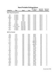
Extinguishing Capacity of Model 570/B570<br />
Approximate Hazard Size<br />
HAZARD AREA QUANTITY<br />
(ft²) (m²) (<strong>lb</strong>s) (kg)<br />
Magnesium Chips 4 .37 6 2.72<br />
Sodium Spill 5 .46 5 2.26<br />
(depth over ½ inch [1.3 cm]) 3 .27 6 2.72<br />
Potassium Spill 5 .46 5 2.26<br />
(depth over ½ inch [1.3 cm]) 3 .27 6 2.72<br />
Sodium Potassium Alloy Spill 3 .27 2 .90<br />
The model 570/B570 <strong>extinguishers</strong> have been manufactured and tested in accordance with the<br />
applicable standards of Factory Mutual to ANSI/UL 711 and ANSI/UL 299. It also complies with<br />
industry standards as presented in the National Fire Protection Association Standard No. 10 "Standard<br />
<strong>for</strong> Portable Fire Extinguishers."<br />
AMEREX CORPORATION DOES NOT SERVICE, MAINTAIN OR RECHARGE FIRE<br />
EXTINGUISHERS. THIS MANUAL IS PUBLISHED AS A GUIDE TO ASSIST<br />
QUALIFIED SERVICE PERSONNEL IN THE INSPECTION, MAINTENANCE AND<br />
RECHARGE OF AMEREX FIRE EXTINGUISHERS ONLY. NO INSTRUCTION<br />
MANUAL CAN ANTICIPATE ALL POSSIBLE MALFUNCTIONS THAT MAY BE<br />
ENCOUNTERED IN THE SERVICE OF FIRE EXTINGUISHERS. DUE TO THE<br />
POSSIBILITY THAT PRIOR SERVICE PERFORMED ON THIS EQUIPMENT MAY<br />
HAVE BEEN IMPROPERLY DONE, IT IS EXTREMELY IMPORTANT THAT ALL<br />
WARNINGS, CAUTIONS AND NOTES IN THIS MANUAL BE CAREFULLY<br />
OBSERVED. FAILURE TO HEED THESE INSTRUCTIONS COULD RESULT IN<br />
SERIOUS INJURY. AMEREX ASSUMES NO LIABILITY FOR SERVICE,<br />
MAINTENANCE OR RECHARGE OF FIRE EXTINGUISHERS BY PUBLISHING THIS<br />
MANUAL.<br />
1
WARNINGS<br />
USE THIS EXTINGUISHER ONLY ON CLASS D BURNING METALS. CLASS D<br />
FIRES NORMALLY GENERATE EXTREMELY HIGH HEAT. AMEREX<br />
RECOMMENDS THE USE OF PROTECTIVE CLOTHING AND SELF-CONTAINED<br />
BREATHING APPARATUS WHILE OPERATING THIS EXTINGUISHER.<br />
TO AVOID RE-IGNITION AFTER A METAL FIRE HAS BEEN EXTINGUISHED, DO<br />
NOT MOVE THE REMAINS UNTIL THE METAL HAS COOLED.<br />
SODIUM CHLORIDE BASED POWDER CAN BE VERY CORROSIVE,<br />
ESPECIALLY ON METALS. AFTER THE FIRE HAS BEEN EXTINGUISHED AND<br />
REMAINS HAVE COOLED, CLEAN ALL SURFACES CONTACTED BY THE DRY<br />
POWDER.<br />
NEVER USE WATER ON A COMBUSTIBLE METAL FIRE. CHEMICAL AND<br />
PRESSURIZING GAS MUST BE MOISTURE FREE.<br />
THIS EXTINGUISHER SHOULD BE PRESSURIZED WITH DRY ARGON ONLY.<br />
PREPARING YOUR NEW EXTINGUISHER FOR USE<br />
THIS MANUAL IS PACKAGED WITH EVERY NEW EXTINGUISHER SHIPPED FROM THE FACTORY. IT<br />
CONTAINS VALUABLE INFORMATION WHICH SHOULD BE STUDIED BY EVERYONE WHO WILL USE OR<br />
SERVICE THE EXTINGUISHER. THE MANUAL SHOULD BE STORED IN A CONVENIENT LOCATION FOR<br />
EASY REFERENCE.<br />
1. Remove the Model 570/B570 and its discharge hose assembly from the shipping carton. Examine both <strong>for</strong><br />
shipping damage.<br />
2. Connect the wand assembly to the extinguisher hose male connector by retracing the locking sleeve on the<br />
wand female swivel coupling. Push the female coupling firmly onto the male swivel adapter and release the<br />
locking sleeve. Tug firmly on the wand to verify that the swivel coupling is completely engaged.<br />
3. Arrange the discharge hose and extension applicator assembly in the retaining clips as shown in the<br />
installation diagrams on page 9.<br />
4. Install your extinguisher in an accessible location with the top of the <strong>hand</strong>le no more than 3½ feet (1 m) above<br />
the floor, the base at least 4 inches (.1 m) above the floor and near a doorway. DO NOT INSTALL IT<br />
WHERE YOU WOULD HAVE TO WALK THROUGH A POTENTIAL FIRE LOCATION TO REACH IT!<br />
5. Do not place this extinguisher close to a potential fire hazard. <strong>Amerex</strong> recommends a location no less than<br />
50 feet (15 m) from the hazard, leaving unobstructed access. Avoid placing it in an extremely hot or cold<br />
place. The operational temperature range is –40°F to +120°F (40°C to +49°C). Adequately protect the<br />
extinguisher if temperatures outside this range are anticipated. Keep the extinguisher clean and free from<br />
dirt, ice, chemicals and any contaminants that may interfere with its proper operation. DO NOT<br />
FUNCTIONALLY TEST THIS FIRE EXTINGUISHER – testing or any use may cause it to gradually lose<br />
pressure and become ineffective. Never throw any extinguisher in a fire as it could explode from<br />
heat/pressure buildup.<br />
NOTE: Slight pressure variances in the gauge reading may be found if the extinguisher has been<br />
subjected to extremes of heat or cold. High temperatures can cause high gauge readings and low<br />
temperatures, low readings. When in doubt condition the extinguisher to 70°F (21°C) <strong>for</strong> several hours to<br />
obtain a more accurate pressure gauge reading.<br />
6. Record the date the extinguisher is being placed into service on the inspection tag and attach it to the<br />
extinguisher.<br />
2
IN CASE OF FIRE<br />
1. HAVE EVERYONE EVACUATE THE AREA IMMEDIATELY!<br />
2. CALL THE FIRE DEPARTMENT EVEN IF THE FIRE APPEARS<br />
TO BE SMALL! THE FIRE DEPARTMENT NUMBER SHOULD<br />
BE POSTED AT EACH TELEPHONE.<br />
3. USE YOUR EXTINGUISHER PROPERLY AND ONLY ON THE<br />
TYPE OF FIRES LISTED ON THE NAMEPLATE (LABEL)!<br />
4. TRAINED PERSONNEL SHOULD FIGHT LARGE FIRES!<br />
5. BE PREPARED TO LEAVE THE AREA IF THE FIRE CANNOT<br />
BE IMMEDIATELY CONTROLLED!<br />
OPERATION<br />
CAUTION: Persons expected to use this extinguisher should be trained in its operation and in the<br />
proper fire fighting technique. "Hands-on" training will prepare personnel with the feel <strong>for</strong> this stored pressure<br />
extinguisher so that the most effective application can be utilized in an emergency situation. The basic operating<br />
instructions are contained in the pictogram portion of every extinguisher nameplate (label). The following<br />
elaborates on these instructions:<br />
1. Hold the extinguisher upright. Twist and pull the ring pin snapping the plastic<br />
seal.<br />
2. Extend the bell shaped nozzle over the fire.<br />
3. Keep the extinguisher upright. Squeeze the lever to discharge the<br />
extinguisher. Cover all burning metal with dry powder until the fire is<br />
extinguished.<br />
NOTE: If greater range is required, disconnect the wand assembly at the<br />
quick connect and use the hose to lob the chemical onto the fire. Be<br />
careful not to spread the fire surface when using this technique.<br />
4. Reapply powder to visible hot spots.<br />
5. To avoid re-ignition allow metal to cool be<strong>for</strong>e cleanup.<br />
6. Evacuate and ventilate the area immediately after use. The fumes and<br />
smoke from any fire may be hazardous and can be deadly.<br />
Model 570<br />
Model B570<br />
Discharge Time (approximate) <strong>30</strong> seconds 24 seconds<br />
Effective ranges:<br />
3-6 feet (with applicator) 1 – 2 m 1 – 2 m<br />
8-10 feet (with nozzle) 2.5 – 3 m 2.5 – 3 m<br />
RECHARGE FIRE EXTINGUISHER IMMEDIATELY AFTER ANY USE<br />
3
INSPECTION<br />
INSPECTION (NFPA-10) is a "quick check" intended to give reasonable assurance that an extinguisher<br />
is fully charged and operable. This is done by seeing that it is in its designated place, that it has not<br />
been actuated or tampered with, and that there is no obvious physical damage or condition to prevent<br />
operation.<br />
PERIODIC INSPECTION PROCEDURES<br />
(Monthly or more often if circumstances dictate)<br />
(NFPA-10) A "quick check" should be made of the extinguisher <strong>for</strong> the following:<br />
1. Located in designated place.<br />
2. No obstructions to access or visibility.<br />
3. Operating instructions on nameplate and facing outward.<br />
4. Seals and tamper indicators not broken or missing.<br />
5. Determine fullness by weighing or "hefting".<br />
6. Examine <strong>for</strong> obvious physical damage, corrosion, leakage or clogged nozzle.<br />
7. Pressure gauge reading in the operable area.<br />
MAINTENANCE<br />
MAINTENANCE (NFPA-10) Maintenance should be per<strong>for</strong>med at least once a year (or more<br />
frequently if indicated by an inspection). Maintenance is a "thorough check" of an extinguisher. It is<br />
intended to give maximum assurance that an extinguisher will operate effectively and safely. It includes<br />
a thorough examination and any necessary repair or replacement. It will normally reveal the need <strong>for</strong><br />
hydrostatic testing.<br />
MAINTENANCE PROCEDURE<br />
1. Clean extinguisher to remove dirt, grease or <strong>for</strong>eign material. Check to make sure that the<br />
instruction nameplate and FM manifest are securely fastened and legible. Inspect the cylinder<br />
<strong>for</strong> corrosion, abrasion, dents or weld damage. If any of these conditions are found and you<br />
doubt the integrity of the cylinder, hydrostatically test to factory test pressure (585 psi [4035<br />
kPa]), using the proof pressure method, in accordance with CGA Pamphlet C-6 and NFPA<br />
Pamphlet 10. See proper method of depressurizing and reclaiming chemical in "Recharge<br />
Procedures". NOTE: When cleaning avoid use of solvents around the pressure gauge. They<br />
could seriously damage the plastic gauge face.<br />
2. Inspect the extinguisher <strong>for</strong> damaged, missing or substitute parts. Only factory replacement<br />
parts are approved <strong>for</strong> use on <strong>Amerex</strong> fire <strong>extinguishers</strong>.<br />
3. Weigh extinguisher and compare with weight printed in the "Maintenance" section on the<br />
nameplate (label). Recharge extinguisher if weight is not within indicated allowable tolerances<br />
(see instructions in "Recharge Procedure").<br />
4. Check the date of manufacture stamped on the bottom of the extinguisher <strong>for</strong> model B570 and<br />
on the wall hanger loop <strong>for</strong> Model 570. Cylinder must be hydrostatically (proof pressure) tested<br />
every 12 years to the test pressure indicated on the nameplate (585 psi [4035 kPa]).<br />
4
5. Visually inspect the pressure gauge:<br />
a. if bent, damaged or improper gauge, depressurize and replace<br />
b. if pressure is low, check <strong>for</strong> leaks<br />
c. if overpressurized (overcharged), depressurize the extinguisher and follow recharge<br />
instructions<br />
6. Remove and check ring pin <strong>for</strong> freedom of movement. Replace if bent or if removal appears<br />
difficult.<br />
7. Inspect the discharge lever <strong>for</strong> dirt or corrosion that might impair free movement. Inspect<br />
carrying <strong>hand</strong>le <strong>for</strong> proper installation. If lever, <strong>hand</strong>le or rivets are damaged, replace with<br />
proper <strong>Amerex</strong> parts.<br />
8. Remove the extension applicator and hose by detaching the female swivel adapter from the hose<br />
and hose from the discharge valve. Inspect the hose, female swivel and extension applicator <strong>for</strong><br />
damage. Make sure that the rubber o-ring inside the female swivel coupling is in place and in good<br />
condition. Replace damaged parts as necessary. Blow air through the hose and extension<br />
applicator assembly to insure that the passage is clear of <strong>for</strong>eign material and powder residue.<br />
Inspect the diffuser in the extension applicator horn – it must be tight to allow proper discharge<br />
characteristics.<br />
9. Visually inspect the inside of the valve body (through the hose connection orifice). Appearance<br />
of powder in the valve may indicate that the extinguisher has been partially discharged and<br />
should be recharged.<br />
10. Inspect the valve body <strong>for</strong> signs of corrosion or damage to the hose thread connection. Replace<br />
valve assembly as necessary following the depressurizing and recharge procedures. If valve<br />
removal is required complete all steps in the "Recharge Procedure".<br />
11. Reconnect the extension applicator to the discharge hose male swivel coupling. Rotate the<br />
hose assembly several times to verify that the swivel operates freely (disconnect again and<br />
clean the inside of the female swivel with a small brush and compressed air if the rotation is<br />
impeded). Arrange the hose and extension applicator assembly according to the installation<br />
instructions on page 9.<br />
12. Install new tamper seal and record service data on the extinguisher inspection tag.<br />
13. Return to its proper location. Install on/in wall hanger bracket, vehicle bracket or dolly cart<br />
making sure that it fits properly. Replace mounting bracket if necessary.<br />
RECHARGE<br />
Recharging (NFPA-10) is the replacement of the extinguishing agent and also includes the expellant<br />
<strong>for</strong> this type of extinguisher.<br />
WARNING:<br />
1. Be<strong>for</strong>e attempting to recharge be sure the extinguisher is completely depressurized.<br />
2. Never have any part of your body over the extinguisher while removing the valve assembly.<br />
3. Use a protective shield between you and the pressure gauge while charging an extinguisher.<br />
Do not stand in front of the gauge if a shield is not available.<br />
5
4. Use a regulated pressurizing source of ARGON ONLY. Set the regulator to no more than 220<br />
psi (1520 kPa).<br />
5. Check and calibrate regulator gauge at frequent intervals. The regulator gauge should be<br />
used to determine when the intended charging pressure has been reached. Do not use the<br />
extinguisher gauge <strong>for</strong> this purpose.<br />
6. Never leave an extinguisher connected to a regulator of a high pressure source <strong>for</strong> an<br />
extended period of time. A defective regulator could cause the cylinder to rupture due to<br />
excessive pressure.<br />
7. Do not mix types of chemicals in <strong>extinguishers</strong>, recharge or recovery systems. Mixing ABC,<br />
Regular, or Purple K dry chemicals with a dry powder agent could cause a serious flare up or<br />
explosion if the dry chemical were to contact a combustible metal fire.<br />
RECHARGE PROCEDURE<br />
1. Per<strong>for</strong>m steps 1 through 4 of the "Complete Maintenance (Six-Year Teardown)" section including<br />
those required in the "Maintenance Procedure."<br />
2. Thoroughly clean all parts with a soft bristle brush or soft cloth. Blow the valve and downtube<br />
out with air or argon. Inspect the collar o-ring, valve stem, spring and downtube assembly –<br />
replace parts if worn or damaged. Lubricate the collar o-ring on the valve stem with Visilox V-<br />
711. DO NOT LUBRICATE THE VALVE STEM SEAL.<br />
3. Reassemble the valve assembly, including downtube, and set aside.<br />
4. Remove any dry powder remaining in the cylinder. Properly dispose of any dry powder that is<br />
contaminated or caked.<br />
5. Inspect the cylinder interior following CGA Visual Inspection Standard, Pamphlet C-6.<br />
6. Fill <strong>Amerex</strong> Model 570/B570 cylinder with <strong>30</strong> pounds (13.6 KG) of <strong>Amerex</strong> Super D (Sodium<br />
Chloride) dry powder. Use <strong>Amerex</strong> dry powder that has been kept moisture and contamination<br />
free.<br />
7. Clean cylinder o-ring seat and threads inside of cylinder collar with a small brush and wipe<br />
surfaces with a clean damp cloth to remove dust. Lightly brush the collar o-ring seat with Visilox<br />
V-711. Install the operating valve/downtube assembly <strong>hand</strong> tight.<br />
8. Attach the charging adapter to the valve discharge port.<br />
WARNING: THIS EXTINGUISHER IS FACTORY PRESSURIZED USING ARGON. ARGON<br />
IS AN INERT GAS THAT WILL NOT ADVERSELY REACT WITH COMBUSTIBLE METALS.<br />
NITROGEN PRESSURIZING GAS COULD CAUSE A REACTION WHEN USED ON CERTAIN<br />
TYPES OF COMBUSTIBLE METAL FIRES. DRY AIR PRESSURIZATION SHOULD NEVER<br />
BE USED, AS EVEN THE SLIGHTEST AMOUNT OF MOISTURE WILL CAUSE A VIOLENT<br />
REACTION WITH CLASS D MATERIALS.<br />
9. With the extinguisher properly secured in an upright position, connect your argon pressurizing<br />
line with a quick connect to the charging adapter. Set the Argon supply cylinder regulator to no<br />
more than 220 psi (1520 kPa). Depress the extinguisher operating valve lever and pressurize<br />
6
the extinguisher with argon to 195 psi (1345 kPa). When the desired pressure has been<br />
reached, release the operating lever. Shut off Argon supply and remove the quick connect.<br />
10. Remove the charging adapter. Check extinguisher <strong>for</strong> leaks by applying leak detecting fluid or a<br />
solution of soapy water to the valve discharge orifice, around the collar o-ring sealing area,<br />
cylinder welds and gauge. Remove leak detecting fluid from valve assembly by blowing out with<br />
air or argon. Wipe exterior of extinguisher to remove any remaining residue.<br />
11. Install the hose assembly to the operating valve. Reconnect the female swivel on the extension<br />
applicator to the male swivel on the hose. Rotate the hose assembly several times to verify that<br />
the swivel operates freely. Disconnect and clean the inside of the swivel female with a small<br />
brush and compressed air if rotation is impeded. Install hose and extension applicator<br />
according to instructions on page 9.<br />
12. Install ring pin and tamper seal. Record recharge date and attach new recharge tag.<br />
13. Weigh assembled extinguisher and confirm that the total weight is within the allowable<br />
tolerances indicated in the "Maintenance" section of the nameplate (label).<br />
COMPLETE MAINTENANCE (SIX YEAR TEARDOWN)<br />
Complete Maintenance (Six Year Teardown) [NFPA-10] Every six years, stored pressure<br />
<strong>extinguishers</strong> that require a 12 year hydrostatic test shall be emptied and subjected to the applicable<br />
maintenance procedures. When the applicable maintenance procedures are per<strong>for</strong>med during periodic<br />
recharging or hydrostatic testing, the six year requirement shall begin from that date.<br />
Note: some states require Complete Maintenance on an Annual Basis. Check with your<br />
<strong>Amerex</strong> servicing distributor to see if this applies to you. NFPA-10 requires that a<br />
"verification of service" external collar tag be installed on the extinguisher whenever "Six<br />
Year Maintenance" is per<strong>for</strong>med. The "verification of service" tag can only be installed if<br />
the operating valve has been removed. A "Six Year Maintenance" service decal must<br />
also be attached to the extinguisher cylinder.<br />
COMPLETE MAINTENANCE (SIX YEAR TEARDOWN) PROCEDURE<br />
1. Discharge powder and pressure into a "closed" dry powder recovery system (several are<br />
commercially available). Make sure that the extinguisher is completely empty and depressurized.<br />
CAUTION: Do not contaminate by mixing with other types of dry powder or dry chemical.<br />
2. Per<strong>for</strong>m all required maintenance in Steps 1 through 8 of "Maintenance Procedure" (Annual).<br />
3. VERIFY THAT NO PRESSURE REMAINS IN THE EXTINGUISHER (slowly squeeze discharge<br />
lever, aiming away from persons or objects which might be injured or damaged), Remove the valve<br />
assembly from the cylinder and inspect it <strong>for</strong> signs of corrosion or damage to the threads. Replace<br />
parts as necessary.<br />
4. Disassemble valve assembly by removing the downtube, spring and valve stem assembly.<br />
Remove the collar o-ring from the valve assembly.<br />
5. Complete steps 2 through 13 of Recharge Procedure.<br />
7
TROUBLESHOOTING GUIDE<br />
WARNING: CHECK TO DETERMINE THE SOURCE OF A LEAK BEFORE THE EXTINGUISHER<br />
IS DEPRESSURIZED. LEAKAGE REPAIRS WILL REQUIRE DEPRESSURIZATION OF THE<br />
EXTINGUISHER AND REMOVAL OF THE VALVE ASSEMBLY. DEPRESSURIZE BY HOLDING THE<br />
EXTINGUISHER IN AN INVERTED POSITION AND SLOWLY SQUEEZING THE DISCHARGE<br />
LEVER. SOME POWDER REMAINING IN THE DOWNTUBE WILL BE EXPELLED SO CARE<br />
SHOULD BE TAKEN IN THE AREA BEING USED FOR DEPRESSURIZING. DO NOT DIRECT<br />
DISCHARGE TOWARD ANY PERSON OR OBJECT WHICH COULD BE INJURED OR DAMAGED.<br />
THOROUGHLY CLEAN ALL VALVE PARTS AFTER DEPRESSURIZATION AND VALVE REMOVAL.<br />
PROBLEM<br />
CORRECTIVE ACTION<br />
1. Leak at operating valve collar o-ring. Remove valve assembly, clean collar thoroughly and<br />
install new collar o-ring. Lubricate with Visilox V-711.<br />
2. Leak through valve. Install new valve stem assembly. Check valve seat <strong>for</strong><br />
scratches or <strong>for</strong>eign matter. Install new valve stem<br />
assembly.<br />
3. Leak around gauge threads. Remove gauge* and reinstall using Teflon tape on the<br />
gauge threads.<br />
4. Defective gauge. Remove defective gauge* and install new P/N 03965<br />
195 psi (1345 kPa) gauge using Teflon tape on the gauge<br />
threads.<br />
5. Leak in the cylinder, Contact <strong>Amerex</strong> if under warranty, otherwise – mark<br />
"Rejected" and remove from service or return to owner.<br />
* Pressure gauge threads are coated with a special epoxy at the factory. For easy<br />
removal soak the valve assembly in hot water (180°F [82°C]) <strong>for</strong> two to four minutes.<br />
Remove gauge with a 1/16" open end wrench.<br />
SIX YEAR LIMITED WARRANTY<br />
<strong>Amerex</strong> warrants its fire <strong>extinguishers</strong> to be free from defects in material and workmanship <strong>for</strong> a period<br />
of six (6) years from the date of purchase. During the warranty period any such defects will be repaired<br />
or the defective extinguisher replaced if the original gray tamper seal is intact and/or if only factory<br />
replacement parts and recommended service have been used to service the extinguisher. This<br />
warranty does not cover defects resulting from modification, alternation, misuse, exposure to unusually<br />
corrosive conditions nor improper installation or maintenance. All implied warranties, including but not<br />
limited to warranties of fitness <strong>for</strong> purpose and merchantability, are limited to the time periods as stated<br />
above. In no event shall <strong>Amerex</strong> Corporation be liable <strong>for</strong> incidental or consequential damages. Some<br />
states do not allow limitations on how long an implied warranty lasts or the exclusion or limitation of<br />
incidental or consequential damages, so that the above limitations or exclusions may not apply to you.<br />
<strong>Amerex</strong> Corporation neither assumes nor authorizes any representative or other person to assume <strong>for</strong><br />
it any obligation or liability other than as expressly set <strong>for</strong>th herein. This warranty gives you specific<br />
legal rights and you may also have other rights that vary from state to state. To obtain per<strong>for</strong>mance of<br />
the obligation of this warranty write to <strong>Amerex</strong> Corporation, P.O. Box 81, Trussville, Alabama 35173 <strong>for</strong><br />
instructions.<br />
8
MOUNTING INSTRUCTIONS<br />
For<br />
Hose and Extension Applicator<br />
Model 570/B570<br />
Extinguisher Installation<br />
Step 1<br />
Install the hose into the Valve<br />
Assembly. Loop the hose as<br />
shown.<br />
Step 2<br />
After looping the hose, snap the<br />
Extension Applicator into both<br />
clips with the bottom of the rubber<br />
<strong>hand</strong>le grip resting on the top clip.<br />
Place the extinguisher into the<br />
model 589 dolly and fasten the<br />
rubber "bungee" straps around<br />
the cylinder. Install the hose and<br />
extension applicator into both<br />
clips as instructed above (steps 1<br />
& 2). DO NOT INSTALL THE<br />
RUBBER STRAPS OVER THE<br />
HOSE & APPLICATOR.<br />
9
19<br />
570<br />
only<br />
PARTS LIST<br />
For<br />
<strong>30</strong> Lb. <strong>Class</strong> D Sodium Chloride Dry Powder<br />
Extinguisher with Hose & Extension Applicator<br />
(Brass Valve)<br />
Model 570/B570<br />
Item<br />
No.<br />
Part<br />
No. Description<br />
Std.<br />
Pkg.<br />
1 11952 Valve Assembly<br />
1A 17144 Hanger Loop & Screw B570<br />
1<br />
2 05240<br />
Collar O-Ring<br />
24<br />
Collar O-Ring (bulk bag)<br />
100<br />
3 10744 Hose Asy w/½ " Male Quick Connect 1<br />
4 10802 ½ " Female Quick Connect<br />
4A 09073 O-Ring <strong>for</strong> Quick Connect<br />
1<br />
5 10800 Extension Applicator<br />
5A 14595 Horn Blk Cl-D<br />
1<br />
6 06978 Hose Gasket (o-ring) 24<br />
7 00160 Ring Pin – stainless steel 24<br />
8 00532 Chain (nylon) <strong>for</strong> Ring Pin 24<br />
9 01387 Lock Wire Seal (Yellow) 500<br />
10 07762 Lever & Rivet 1<br />
11 01563 Rivet only <strong>for</strong> lever 24<br />
12 09020 Handle & Rivets 1<br />
13 01564 Rivets only <strong>for</strong> Handle (2 required) 24<br />
14 03965 Gauge – 195 psi 6<br />
15 05243 Valve Stem O-Ring 24<br />
16 06093<br />
Valve Stem Assembly<br />
6<br />
Valve Stem Assembly (bulk bag)<br />
96<br />
17 17139 Spring 6<br />
18<br />
17215 D'tube/Retainer Asy (model 570)<br />
17214 D'tube/Retainer Asy (model B570)<br />
1<br />
19 16904<br />
Strap & Hose Clip Asy (black plastic)<br />
3/8" (2 reqd. per extinguisher)<br />
1<br />
20 08281 Label (Fire Ratings) 1<br />
21 01007 Wall Hanger Bracket 570<br />
21A 00577 Wall Hanger Bracket B570<br />
1<br />
22<br />
12383 Protective Ring <strong>for</strong> Btm of Cyl – 570<br />
12952 Protective Ring <strong>for</strong> Btm of Cyl – B570<br />
1<br />
23 0<strong>30</strong>38 Hydrotest Adapter 1<br />
24 02141<br />
Fill Adapter, Hansen Quick Connect<br />
Type 5/8" UNF Thread<br />
1<br />
NOTE:<br />
All valve assemblies include new valve body, gauge,<br />
lever and <strong>hand</strong>le<br />
22<br />
21<br />
23<br />
24<br />
21A<br />
10