120v & 240v CAPFM Heating Mat Installation guide - Warmup
120v & 240v CAPFM Heating Mat Installation guide - Warmup
120v & 240v CAPFM Heating Mat Installation guide - Warmup

Create successful ePaper yourself
Turn your PDF publications into a flip-book with our unique Google optimized e-Paper software.
<strong>Installation</strong> steps (3)<br />
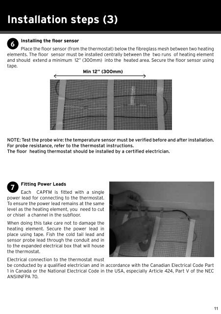
Installing the floor sensor<br />
6<br />
Place the floor sensor (from the thermostat) below the fibreglass mesh between two heating<br />
elements. The floor sensor must be installed centrally between the two runs of heating element<br />
and should extend a minimum 12” (300mm) into the heated area. Secure the floor sensor using<br />
tape.<br />
Min 12” (300mm)<br />
NOTE: Test the probe wire: the temperature sensor must be verified before and after installation.<br />
For probe resistance, refer to the thermostat instructions.<br />
The floor heating thermostat should be installed by a certified electrician.<br />
Fitting Power Leads<br />
7<br />
Each <strong>CAPFM</strong> is fitted with a single<br />
power lead for connecting to the thermostat.<br />
To ensure the power lead remains at the same<br />
level as the heating element, you need to cut<br />
or chisel a channel in the subfloor.<br />
When doing this take care not to damage the<br />
heating element. Secure the power lead in<br />
place using tape. Fish the cold tail lead and<br />
sensor probe lead through the conduit and in<br />
to the expanded electrical box that will house<br />
the thermostat.<br />
Electrical connection to the thermostat must<br />
be conducted by a qualified electrician and in accordance with the Canadian Electrical Code Part<br />
1 in Canada or the National Electrical Code in the USA, especially Article 424, Part V of the NEC<br />
ANSIINFPA 70.<br />
11