K 16 J LM 1103 b4 PE N - SEZ Krompachy
K 16 J LM 1103 b4 PE N - SEZ Krompachy
K 16 J LM 1103 b4 PE N - SEZ Krompachy

You also want an ePaper? Increase the reach of your titles
YUMPU automatically turns print PDFs into web optimized ePapers that Google loves.
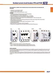
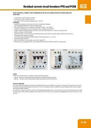
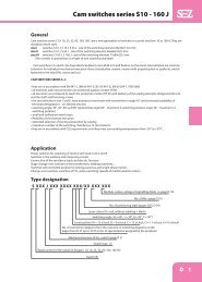
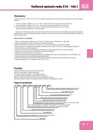
Compact power switches K <strong>16</strong> J a K 32 J<br />
Use<br />
Compact power switches K<strong>16</strong>J and K32J are 2 modules, 3poles switches of rated current <strong>16</strong>A and 32A with<br />
switching angle 90°. Switches can be mounted on DIN rail, or on base plate with M4 bolts. They can also be<br />
mounted on the front panel of distribution box with 2 self tapping screws Ø 3,9. Access to heads of the<br />
screws for connection of conductors is in this case from the back side of the switch and the switch is without<br />
back fixing rail. O basic execution of 3 poles switches K<strong>16</strong>J and K32J you can add 4-th and 5-th switching<br />
pole, or <strong>PE</strong> and N poles. These units can be attached to the switches without screws from the left or right<br />
side. Extentions front plates of operatings elements, mechanical executions and numeric designation of<br />
electrical schemes are identical with cam switches S<strong>16</strong>J and S25J.<br />
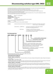
Example of type designation:<br />
K <strong>16</strong> J <strong>LM</strong> <strong>1103</strong> B4 <strong>PE</strong> N<br />
two terminals for N wires <strong>16</strong> mm 2<br />
two terminals for <strong>PE</strong> wires <strong>16</strong> mm 2<br />
electrical execution (3 pole switch - 90°)<br />
small handle<br />
DIN rail execution<br />
type and rated current of the switch (<strong>16</strong> A, 32 A)<br />
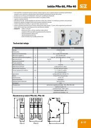
Technical data<br />
TY<strong>PE</strong> K<strong>16</strong>J K32J<br />
Standards STN EN 60947-3<br />
Rated insulating voltage Ui V 690 690<br />
Rated impulse voltage Uimp kV 4 4<br />
Rated thermal current Ith – Ithe A <strong>16</strong> 32<br />
Output in AC3 at 500 V~ ( motors ) kW 7,5 11<br />
Rated operating current Ie v AC 23 A – 500 V~ A <strong>16</strong> 32<br />
Rated switching-on capacity A <strong>16</strong>0 320<br />
Rated switching-off capacity A 128 256<br />
Conditional short-circuit current with fuse <strong>16</strong>, 35 A kA 6 6<br />
Mechanical endurance 100 000 cykles 100 000 cykles<br />
Max. cross section of conductors mm 2 <strong>16</strong> <strong>16</strong><br />
Protection degree IP 20<br />
IP 40 from the front panel<br />
Switching angle 90°<br />
Ambient temperature °C -30 till +55<br />
Mounting on panel, DIN rail 35 x 7,5<br />
Rated operating current Ie (A) at DC 22/21 48 V <strong>16</strong> 32<br />
110 V 1 1<br />
220 V 0,5 0,5<br />
Technical parameters for switching pole SP <strong>16</strong>, SP 32 and range of connecting terminals for N32 and N<strong>16</strong> are identical<br />
with data in chart – Technical data.<br />
D 52
Compact power switches K <strong>16</strong> J a K 32 J<br />
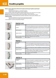
Execution: Type: Description:<br />
* Switches with rear mounting K...J<strong>LM</strong> - with small handle for DIN rail or with screws<br />
K...JB - with control on the door<br />
K...JP - in plastic box with IP 65<br />
Switches on panel K...J - with handle<br />
K...JM - with small handle<br />
K...JG - with handle and sealing for IP 65 (also for execution D,U...)<br />
K...JD - with handle and front plate<br />
K...JU - with lock and 3 padlock - cylindrical<br />
K...JH - with locking padlocks on handle<br />
K...JF - with LED signalling diode<br />
Accessories SP <strong>16</strong><br />
SP 32<br />
- switching pole with terminals 7-8 or 9-10<br />
<strong>PE</strong> <strong>16</strong><br />
<strong>PE</strong> 32<br />
- nonswitched pole for two earthing conductors till <strong>16</strong> mm 2<br />
N <strong>16</strong> - nonswitched pole for conductors till <strong>16</strong> mm 2 terminals for central conductors<br />
N 32<br />
* For these types there is a possibility of adding front plate and lock with 3 padlocks U, small handle M and handle H.<br />
Numeric designation of switches:<br />
1102 B4 – 2 pole switch<br />
<strong>1103</strong> B4 – 3 pole switch<br />
1104 B4 – 4 pole switch<br />
1105 B4 – 5 pole switch<br />
Application<br />
- 2 to 5 poles switches in AC 21, AC 23 and AC 3 categories(switches for resistive and inductive loads, motors)<br />
- switches in distributions with 3 and 5 conductors with <strong>PE</strong> a N terminals<br />
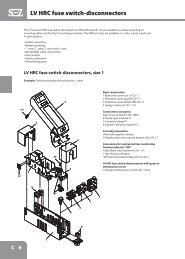
GUIDE FOR AUXILIARY SWITCH SP<br />
Auxiliary switch SP can be mounted to all types of switches K..J, due to increased number of switching poles from<br />
three to four or five.<br />
For correct mounting, following conditions have to be observed:<br />
1. For switches K<strong>16</strong>J use auxiliary switch SP<strong>16</strong>, for switches K32J use auxiliary switch SP32<br />
2. Auxiliary switches with terminals marked 7 – 8 are mounted to the right side of switches K..J, auxiliary switches<br />
with terminals marked 9-10 to the left side of switches K..J.<br />
3. Auxiliary switches SP with screw head from the front of the device (front of the device is marked with <strong>SEZ</strong> logo)<br />
are intended for attaching on mounting plate or DIN rail, i.e. for switches K..JL. Auxiliary switches with screw head<br />
from the back side of the device are intended for switches K..J, i.e. for gripping the switch from the front side.<br />
Guide for mounting of SP:<br />
1. Put contacts of the switch K..J to the closed position, i.e. handle in position „I“.<br />
2. Slide the auxiliary switch onto switch K..J in the way that projections are directed to apertures of K..J. Slightly<br />
push the side of SP and both devices will join together.<br />
3. The function of the device can be checked by changing the position of the handle of the switch to „I“ and „0“ and<br />
checking the closing and opening of the contacts of SP.<br />
D 53
Compact power switches K <strong>16</strong> J a K 32 J<br />
GuIDE FOR NON-SWITCHING POLE „N“ AND „<strong>PE</strong>“<br />
Non-switching pole „N“ and „<strong>PE</strong>“ can be mounted to all types of switches K..J, , due to increased number of terminals of<br />
the switch K..J for gripping the conductors N and <strong>PE</strong>.<br />
For correct mounting, following conditions have to be observed:<br />
1. For switches K<strong>16</strong>J use non-switching pole N<strong>16</strong> or <strong>PE</strong><strong>16</strong> and for switches K32J use non-switching pole N32 or <strong>PE</strong>32.<br />
2. Non-switching poles with terminals marked N-N are mounted to the right side of switches K..J, non-switching poles<br />
with terminals marked <strong>PE</strong>-<strong>PE</strong> to the left side of switches K..J.<br />
3. Non switching poles N a <strong>PE</strong> with screw head from the front of the device (front of the device is marked with <strong>SEZ</strong> logo)<br />
are intended for attaching on mounting plate or DIN rail, i.e. with marking of the switch K..JL. Non-switching poles with<br />
screw head from the back side of the device are intended for switches K..J, i.e. for gripping the switch from the front<br />
side.<br />
Guide for mounting of N a <strong>PE</strong>:<br />
Slide the non-switching pole N, or <strong>PE</strong> onto the switch K..J in the way that projections are directed to apertures of K..J.<br />
Slightly push the side of N or <strong>PE</strong> and both devices will join together.<br />
Push here<br />
D 54
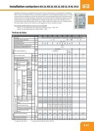
Compact power switches K <strong>16</strong> J a K 32 J<br />
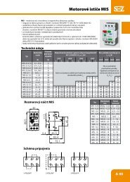
Dimensional drawing:<br />
K 32 JDM<br />
K 32 J<br />
K 32 JM<br />
K 32 JD<br />
K 32 JLu<br />
K 32 JPu<br />
K 32 JLu<br />
K 32 J<strong>LM</strong><br />
K 32 Ju<br />
K 32 JPM<br />
D 55