cam switches s ... j - SEZ Krompachy
cam switches s ... j - SEZ Krompachy
cam switches s ... j - SEZ Krompachy

Create successful ePaper yourself
Turn your PDF publications into a flip-book with our unique Google optimized e-Paper software.
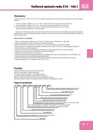
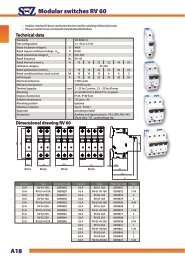
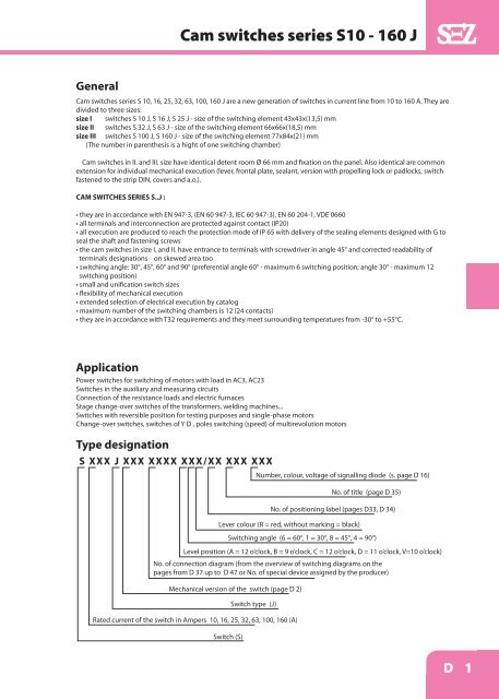
Cam <strong>switches</strong> series S10 - 160 J<br />
General<br />
Cam <strong>switches</strong> series S 10, 16, 25, 32, 63, 100, 160 J are a new generation of <strong>switches</strong> in current line from 10 to 160 A. They are<br />
divided to three sizes:<br />
size I <strong>switches</strong> S 10 J, S 16 J, S 25 J - size of the switching element 43x43x(13,5) mm<br />
size II <strong>switches</strong> S 32 J, S 63 J - size of the switching element 66x66x(18,5) mm<br />
size III <strong>switches</strong> S 100 J, S 160 J - size of the switching element 77x84x(21) mm<br />
(The number in parenthesis is a hight of one switching chamber)<br />
Cam <strong>switches</strong> in II. and III. size have identical detent room Ø 66 mm and fixation on the panel. Also identical are common<br />
extension for individual mechanical execution (lever, frontal plate, sealant, version with propelling lock or padlocks, switch<br />
fastened to the strip DIN, covers and a.o.).<br />
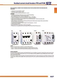
CAM SWITCHES SERIES S..J :<br />
• they are in accordance with EN 947-3, (EN 60 947-3, IEC 60 947-3), EN 60 204-1, VDE 0660<br />
• all terminals and interconnection are protected against contact (IP20)<br />
• all execution are produced to reach the protection mode of IP 65 with delivery of the sealing elements designed with G to<br />
seal the shaft and fastening screws<br />
• the <strong>cam</strong> <strong>switches</strong> in size I. and II. have entrance to terminals with screwdriver in angle 45° and corrected readability of<br />
terminals designations on skewed area too<br />
• switching angle: 30°, 45°, 60° and 90° (preferential angle 60° - maximum 6 switching position; angle 30° - maximum 12<br />
switching position)<br />
• small and unification switch sizes<br />
• flexibility of mechanical execution<br />
• extended selection of electrical execution by catalog<br />
• maximum number of the switching chambers is 12 (24 contacts)<br />
• they are in accordance with T32 requirements and they meet surrounding temperatures from -30° to +55°C.<br />
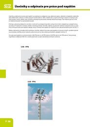
Application<br />
Power <strong>switches</strong> for switching of motors with load in AC3, AC23<br />
Switches in the auxiliary and measuring circuits<br />
Connection of the resistance loads and electric furnaces<br />
Stage change-over <strong>switches</strong> of the transformers, welding machines...<br />
Switches with reversible position for testing purposes and single-phase motors<br />
Change-over <strong>switches</strong>, <strong>switches</strong> of Y D , poles switching (speed) of multirevolution motors<br />
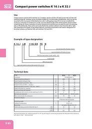
Type designation<br />
S XXX J XXX XXXX XXX/XX XXX XXX<br />
Number, colour, voltage of signalling diode (s. page D 16)<br />
No. of title (page D 35)<br />
No. of positioning label (pages D33, D 34)<br />
Lever colour (R = red, without marking = black)<br />
Switching angle (6 = 60°, 1 = 30°, 8 = 45°, 4 = 90°)<br />
Level position (A = 12 o’clock, B = 9 o’clock, C = 12 o’clock, D = 11 o’clock, V=10 o’clock)<br />
No. of connection diagram (from the overview of switching diagrams on the<br />
pages from D 37 up to D 47 or No. of special device assigned by the producer)<br />
Mechanical version of the switch (page D 2)<br />
Switch type (J)<br />
Rated current of the switch in Ampers 10, 16, 25, 32, 63, 100, 160 (A)<br />
Switch (S)<br />
D 1
Cam <strong>switches</strong> series S10 - 160 J<br />
Order example:<br />
S16J VDG 2203X A6 R/ 01 N01 1R4<br />
As an example, the following <strong>cam</strong> switch is specified:<br />
• <strong>cam</strong> switch with rated current 16 A<br />
• with reversible position (V), with frontal plate (D), with rubber insulation for IP65 (G)<br />
• three - pole switch (2203) without interconnector (X)<br />
• basic position of the lever A (12 hod), switching angle 60° (6)<br />
• red lever (R)<br />
• label position 01 with inscription MASTER SWITCH<br />
• switch with 1 indication diode (red) for voltage 230 V~<br />
When specifying the switch, is necessary use the base catalog with mechanical and electrical charts.<br />
For substandard version of switch is necessary supply the specification sheet and send it to producer.<br />
When no required position, switching angle, label position or inscription is stated, the A lever position (12 Hours), switching<br />
angle of 60° or other<br />
regarding to required switching programme and relevant position label will be determined by the producer.<br />
Label, inscription and LED diode No. are to be stated if they are resulted from mechanical execution and they are required specifically.<br />
(Type designation up to vertical dividing line).<br />
Mechanical Execution<br />
Switch with fixing to the panel (front mounting)<br />
Type designation Execution description<br />
S ... J<br />
With lever (without frontal plate)<br />
S ... JG With lever and rubber insulation for IP 65<br />
S ... JD<br />
With lever and frontal plate<br />
S ... JZ<br />
With the zero position (or other required positions -cite) to be locked with propelling lock<br />
S ... JU<br />
Switch with possibility to be locked by 3 padlocks<br />
S ... JF<br />
Switch with light alarm (1-3 LED diodes)<br />
S ... JV Switch with one or two reversible positions (only switch S 10, 16, 25 J)<br />
S ... JR Central fixing of the switch to the hole of 22 diameter with control by lever (only S 10, 16, 25 J)<br />
S ... JK Central fixing of the switch to the hole of 22 diameter with control by key (only S 10, 16, 25 J)<br />
S ... JT<br />
Switch with inhibiting push-button in zero position (only S 10, 16, 25 J) - other position cite<br />
S ... JC Switch with undervoltage coil 230 V~ (only for S 32, 63 J)<br />
Switches with rear fixing (reversed mounting)<br />
Type designation Execution description<br />
S ... JO<br />
Rear fixing of <strong>switches</strong> (reversed mounting)<br />
S ... JLD Switch with frontal plate fastened to the strip TH 35-7,5<br />
S ... JLS Switch fastened to the strip TH 35-7,5, with label 52,5x45 mm (only S 10, 16, 25 J)<br />
S ... JB Rear fixing of switch - with lever in the door<br />
S ... JBD<br />
- with lever and frontal plate in the door<br />
S ... JBU<br />
- with lockable lever in the door<br />
S ... JBZ<br />
- with propelling lock in the door<br />
S ... JP<br />
Switch in the box with lever (IP65)<br />
S ... JPD<br />
Switch in the box with frontal plate (IP65)<br />
S ... JPU<br />
Switch in the box with lockable lever (IP65)<br />
S ... JPZ<br />
Switch in the box with propelling lock (IP65)<br />
S ... JA In Al cover (S 10 - 63 J)<br />
S ... JAZ In Al cover with propelling lock (S 10 - 63 J)<br />
S ... JI In Al cover with 3 fuses (S 10 - 63 J)<br />
S ... JIZ In Al cover s 3 fuses and propelling lock (S 10 - 63 J)<br />
S ... NJ In cover from plastic material with 3 fuses (S 10, 16, 25 J)<br />
S ... NJU<br />
In cover from plastic material with 3 fuses and lockable level 1 - 3 padlocks (S 10,16,25J)<br />
S ... NJZ<br />
In cover from plastic material and 3 fuses and propelling lock( S10,16,25J)<br />
S ... JM<br />
With small lever<br />
S ... JH<br />
With locking lever S 10 -25 J<br />
D 2
Cam <strong>switches</strong> series S10 - 160 J<br />
Notes: All mechanical execution of <strong>switches</strong> are each other combinable, for example S16JVDG is switch with rated current 16A,<br />
with reversible position (V), with frontal plate (D) and rubber insulation (G) for IP 65. Execution JV, JR, JK, JLS is possible only<br />
for <strong>switches</strong> S 10, 16, 25 J (I. size group).<br />
Another individual requirements for machanical execution are possible and will be determined by the producer.<br />
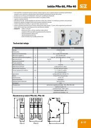
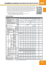
Technical data<br />
Type designation S10J S16J S25J S32J S63J S100J S160J<br />
Rated voltage U i<br />
, V * 690 ** 690 ** 690 ** 690 690 690 690<br />
Rated pulse standing voltage U imp<br />
, kV 4 4 4 6 6 6 6<br />
Rated thermal current I th<br />
, A 10 20 25 40 63 100 150<br />
Rated operational current I e<br />
, A AC-21A - resistance load with slight overload, AC- 1- low - inductive loads<br />
Rated operational power output, kW 10 16 25 32 60 100 150<br />
AC-3 - short - circuit armature motors Triggering, switching-off during the run<br />
1 phase 220-240V 1,5 / 8,5 1,7 / 9,6 2,6 / 14,7 4 / 22,7 5 / 28,4 10 / 56,8 13 / 73,8<br />
3 phase 220-240V 2,5 3 4,5 7 8,5 17 23<br />
380-440V 3,5 / 6,3 4 / 7,2 7,5 / 13,5 12 / 21,6 15 / 27 30 / 54 40 / 72<br />
500V 3,5 4 7,5 12 15 30 40<br />
AC-23A switching the motor and high- 1 phase 220-240V 1,7 / 9,6 2,3 / 13 3 / 17 5 / 28,4 10 / 56,8 13 / 73,8 18 / 102<br />
-inductive loads<br />
3 phase 220-240V 3 4 5,5 8 17 23 30<br />
380-440V 6 / 10,8 7,5 / 13,5 11 / 19,8 15 / 27 30 / 54 40 / 72 55 / 99<br />
500V 6 7,5 11 15 30 40 55<br />
Rated operational current - DC, I e<br />
, A 24V 10/8 16/8 25/8 32/12 63/25 100/32 150/63<br />
(with one switching contact) 48V 6/4 6/4 6/4 25/10 25/16 32/20 32/20<br />
DC-21A / DC-22A 110V 1/0,3 1/0,3 1/0,3 4/3 4/3 5/4 5/4<br />
(resistance load/shunt-excited motors) 220V 0,3/0,2 0,3/0,2 0,3/0,2 1/0,4 1/0,4 1,2/0,5 1,2/0,5<br />
Rated short-time standing current - 1s 4 5 5 10 8 10 10<br />
I cw<br />
, A 10 16 25 32 63 100 160<br />
Rated short-time standing current - 1s, I cw<br />
, A 200 220 500 800 1200 1500 2000<br />
Rated short circuit making capacity I cm<br />
, A 400 400 500 800 1200 1500 1600<br />
Mechanical endurance (number of operations) 106 106 106 3x10⁵ 3x10⁵ 3x10⁵ 105<br />
Connecting wires, mm 2 0,75-4 1-4 1,5-4 2,5-16 6-16 16-50*** 16-50 ***<br />
Connecting screw M4 M4 M4 M5 M5 M6x0,75 M6x0,75<br />
Control winch o 5 o 5 o 6 o 6 o 6 o 6 o 6<br />
Pozn.: * actual for network with earth neutral point, category of overvoltage III. and rate of contaminated 2; Ui = 500,<br />
if rate of contaminated. 3.<br />
** Switch as master switch (execution S...JU) reduction of Ui to 400 V.<br />
*** For one full Cu wire with maximum cross-section 70 mm 2 .<br />
D 3
Cam <strong>switches</strong> series S10 - 160 J<br />
SWITCHES TO THE PANEL<br />
execution S ... J, JD, JG, JZ, JU, JR, JK, JV, JT, JF, JC<br />
DIMENSIONS [mm]<br />
Type A B C D E F G H I J K M N O P R S H1 U V X Y Z<br />
S 10, 16, 25 J 48 36 66 8 14 24 1,5 13,5 9 31 35 M4 23 3 24 30 43 5 5,5 43 19 4,2 46<br />
S 32, 63 J 94 75 106 11 22 46 2 18,5 10 42 50 M5 30 4 35 50 66 6 7,5 66 34,5 5,4 74<br />
S 100, 160 J 94 75 106 11 22 46 2 21 10 42 50 M5 30 4 35 50 77 6 7,5 85 34,5 5,4 74<br />
Type<br />
L with the No. of chambers<br />
1 2 3 4 5 6 7 8 9 10 11 12<br />
S 10, 16, 25 J 33,5 47 60,5 74 87,5 101 114,5 128 141,5 155 168,5 182<br />
S 32, 63 J 42 60,5 79 97,5 116 134,5 153 171,5 190 208,5 227 245,5<br />
S 100, 160 J 45 66 87 108 129 150 171 192 213 234 255 276<br />
SWITCHES IN CASES WITH REAR FASTENING<br />
execution S ... JO, JLS, JLD, JB, JBD, JBU, JBZ, JP, JPU, JPD, JA, JI, JAZ, JIZ, NJ, NJU<br />
DIMENSIONS [mm]<br />
Type A B C D E F G H I J K M N O P R S H1 U V X Y Z<br />
S 10, 16, 25 J 48 36 66 8 14 24 1,5 13,5 9 31 35 M4 23 3 24 30 43 5 5,5 43 19 4,2 46<br />
S 32, 63 J 94 75 106 11 22 46 2 18,5 10 42 50 M5 30 4 35 50 66 6 7,5 66 34,5 5,4 74<br />
S 100, 160 J 94 75 106 11 22 46 2 21 10 42 50 M5 30 4 35 50 77 6 7,5 85 34,5 5,4 74<br />
Type Z1 V1 S1 B1 B2 U1 U2 L1 L2 L3 D1 D2 D3 A1 F1 A2 C1<br />
S 10, 16, 25 J 22 110 87 66 73 5,5 10,5 86 100 159 64 14 8 72 35 48 66<br />
S 32, 63 J 30 160 140 110 110 6,5 12 108 140 84 16 10 119 58 66 66<br />
S 100 J 30 160 140 110 110 6,5 12 140 84 16 10 119 58 66 106<br />
Type<br />
T with the No. of chambers<br />
1 2 3 4 5 6 7 8 9 10 11 12<br />
S 10, 16, 25 J 90 103,5 117 130,5 144 157,5 171 184,5 198 211,5 225 238,5<br />
S 32, 63 J 102,5 121 139,5 158 176,5 195 213,5 232 250,5 269 287,5 306<br />
S 100, 160 J 105 126 147 168 189 210 231 252 273 294 315 336<br />
Type<br />
L4 with the No. of chambers<br />
1 2 3 4 5 6 7 8 9 10 11 12<br />
S 10, 16, 25 J 62 62 76 130 130 130 130 197,5 197,5 197,5 197,5 197,5<br />
S 32, 63 J 115 115 115 115 172 172 172 256 256 256 298 298<br />
S 100, 160 J 115 115 115 172 172 172 256 256 256 256 298 298<br />
Type<br />
Max. No. of chambers<br />
L1 L2 L3<br />
S 10, 16, 25 J 2 3 7<br />
S 32, 63 J 2 4 -<br />
S 100 J 3 - -<br />
D 4
Cam <strong>switches</strong> series S10 - 160 J<br />
CAM SWITCHES S ... J<br />
- switch with lever without frontal plate<br />
S 10, 16, 25 J<br />
S 10, 16, 25,32, 63 J<br />
Clamping to the panel (front mounting)<br />
S 32, 63 J<br />
S 100, 160 J<br />
S 100, 160 J<br />
D 5
Cam <strong>switches</strong> series S10 - 160 J<br />
S 10, 16, 25 JD<br />
CAM SWITCHES S ... JD<br />
- switch with lever and frontal plate<br />
S 10, 16, 25,32, 63 JD<br />
S 32, 63 JD<br />
Clamping to the panel (front mounting)<br />
S 100, 160 JD<br />
S 100, 160 JD<br />
D 6
Cam <strong>switches</strong> series S10 - 160 J<br />
CAM SWITCHES S ... Ju<br />
- switch with possibility to be locked by 3<br />
padlocks ( Ø 5-8 mm)<br />
- switch as master or emergency switch<br />
S 10, 16, 25 Ju<br />
S 10, 16, 25,32, 63 Ju<br />
S 32, 63 Ju<br />
Clamping to the panel (front mounting)<br />
S 100, 160 Ju<br />
S 100, 160 Ju<br />
D 7
Cam <strong>switches</strong> series S10 - 160 J<br />
S 10, 16, 25 Jz<br />
CAM SWITCHES S ... Jz<br />
- Switch with the zero position (or other required<br />
positions) to be locked with propelling lock<br />
S 10, 16, 25,32, 63 Jz<br />
S 32, 63 Jz<br />
Clamping to the panel (front mounting)<br />
S 100, 160 Jz<br />
S 100, 160 Jz<br />
D 8
Cam <strong>switches</strong> series S10 - 160 J<br />
CAM SWITCHES S ... JV<br />
- Switch with one or two reversible positions also through more positions<br />
- Maximum possible angel of reversible control 120°<br />
- When specifying the switch, is necessary state (<strong>switches</strong> with two and more positions) the reversible and locking<br />
position, for example the switch with switching position 0-1-2 by move from position 2 to 1 is signify as V2-A1<br />
S 10, 16, 25 JVD<br />
S 10, 16, 25 JV<br />
Clamping to the panel (front mounting)<br />
Number of switching<br />
chambers<br />
1 2 3 4 5 6 7 8 9 10 11 12<br />
L (mm) 47 60,5 74 87,5 101 114,5 128 141,5 155 168,5 182 195,5<br />
D 9
Cam <strong>switches</strong> series S10 - 160 J<br />
S 10, 16, 25 JG<br />
CAM SWITCHES S ... JG<br />
- Switch with rubber insulation for IP 65<br />
S 10, 16, 25,32, 63 JG<br />
S 32, 63 JG<br />
Clamping to the panel (front mounting)<br />
S 100, 160 JG<br />
S 100, 160 JG<br />
S 10 - 25 J S 32 - 160 J<br />
A - Fixation by two self tapping screws D4 D5<br />
B - Fixation by two bolts and nuts M4 M5<br />
D 10
Cam <strong>switches</strong> series S10 - 160 J<br />
CAM SWITCHES S ... JDG<br />
- Switch with frontal plate and rubber insulation for IP 65<br />
S 10, 16, 25 JDG<br />
S 10, 16, 25,32, 63 JDG<br />
Clamping to the panel (front mounting)<br />
S 32, 63 JDG<br />
S 100, 160 JDG<br />
S 100, 160 JDG<br />
1<br />
S 10 - 25 J S 32 - 160 J<br />
A - Fixation by two self tapping screws D4 D5<br />
B - Fixation by two bolts and nuts M4 M5<br />
D 11
Cam <strong>switches</strong> series S10 - 160 J<br />
S 10, 16, 25 JR<br />
CAM SWITCHES S ... JR<br />
- Central fixing of the switch to the hole of Ø 22 mm<br />
diameter, JRG : JR + rubber seal G<br />
- Control by lever<br />
Fixing outlet for panel<br />
Number of switching<br />
chambers<br />
1 2 3 4 5 6 7 8 9 10 11 12<br />
L (mm) 54,5 68 81,5 95 108,5 112 135,5 149 162,5 176 189,5 203<br />
D 12
Cam <strong>switches</strong> series S10 - 160 J<br />
CAM SWITCHES S ... JK<br />
- central fastening <strong>cam</strong> switch to the Ø 22 mm<br />
diameter hole using bajonet machanism<br />
- control by key<br />
S 10, 16, 25 JK<br />
Fixing outlet for panel<br />
Number of switching<br />
chambers<br />
1 2 3 4 5 6 7 8 9 10 11 12<br />
L (mm) 54,5 68 81,5 95 108,5 112 135,5 149 162,5 176 189,5 203<br />
D 13
Cam <strong>switches</strong> series S10 - 160 J<br />
S 32, 63 JCD<br />
CAM SWITCHES S ... JC<br />
- switch with undervoltage coil (the switch<br />
switched off selfactually when the voltage<br />
in the inlet terminal is OFF)<br />
- possibility of switching on from 85% un and more<br />
- possibility of switching off from 85% un and less,<br />
necessity to switch off from 35% un<br />
- undervoltage coil terminals are marked as A1 - A2,<br />
coil voltage 230 V ~<br />
- designed for second dimensional size 32, 63 A<br />
- mounting on panels, into enclosures<br />
- advantage: no voltage on coil terminals<br />
of electromagnet in OFF position<br />
- application: as 3 pole OFF <strong>switches</strong> - 1103 A6<br />
as reverse changeover <strong>switches</strong> - 9151 C6<br />
4x 5,4<br />
MAX. 5 mm A B<br />
69,5<br />
94<br />
94<br />
35 11<br />
23<br />
18,5 18,5 18,5 7<br />
A - shunt trip<br />
b - contacts switch<br />
D 14
Cam <strong>switches</strong> series S10 - 160 J<br />
CAM SWITCHES S ... JT<br />
- switch with lever without frontal plate switch with<br />
push button which blocks lever in zero position<br />
S 10, 16, 25 JT<br />
S 10, 16, 25,32, 63 JT<br />
S 32, 63 JT<br />
1<br />
Clamping to the panel (front mounting)<br />
Y<br />
lever<br />
G - green<br />
R - red<br />
Y - yellow<br />
unlabeled - black<br />
S 100, 160 JT<br />
S 100, 160 JT<br />
D 15
Cam <strong>switches</strong> series S10 - 160 J<br />
S 10, 16, 25 JF<br />
CAM SWITCHES S ... JF<br />
- Switch with light alarm in selected position<br />
JF<br />
Clamping to the panel (front mounting)<br />
JzF<br />
S 32, 63 JF<br />
LED<br />
diode<br />
outlet<br />
Specification of LED diode<br />
Lock LED diode<br />
3 or 4-character code, at the end of the technical specification of<br />
switch (see„Order sheet example“ page D 2)<br />
For example:<br />
2 RG 0<br />
Driving voltage of LED diode (”24 V ~” - see chart 2)<br />
LED diode color (”red / green” - see chart 1)<br />
Number of LED diodes 2 (1, 2 or 3)<br />
S 100, 160 JF<br />
2 R.G 0<br />
Driving voltage of LED diode („24 V ~“ – see chart. 2)<br />
LED diode color two-tone („red/green“ – see chart. 1)<br />
Number of LED diodes 2 (1, 2 or 3 pcs)<br />
Chart 1<br />
Color<br />
Symbol<br />
Red<br />
R<br />
Green<br />
G<br />
Orange<br />
E<br />
Yellow<br />
Y<br />
Other possible combinations (2-color<br />
LED diode): RG, YG, EG, EY<br />
Chart 2<br />
Voltage 24 V 48 V 60 V 110 V 230 V<br />
Alternative 0 1 2 3 4<br />
Direct 5 6 7 8 9<br />
D 16<br />
Note: LED diode constructors are connected to individual terminals<br />
at the end of the switch, other requirements, please consult<br />
with manufacturer.
Cam <strong>switches</strong> series S10 - 160 J<br />
CAM SWITCHES S ... JO<br />
- Switch with rear fixing<br />
S 10, 16, 25 JO<br />
S 10, 16, 25,32, 63 JO<br />
1<br />
4<br />
Rear fixing outlets<br />
3,2<br />
S 32, 63 JO<br />
S 100, 160 JO<br />
S 100, 160 JO<br />
1<br />
4<br />
D 17
Cam <strong>switches</strong> series S10 - 160 J<br />
S 10, 16, 25 JLS<br />
CAM SWITCHES S ... JLS<br />
- Switch fastened to the strip TH 35 - 7,5 with label<br />
- Execution JL with lever, without label<br />
Number of switching<br />
chambers<br />
1 2 3 4 5 6 7 8 9 10 11 12<br />
L (mm) 39 52,5 66 79,5 93 106,5 120 133,5 147 160,5 174 187,5<br />
D 18
Cam <strong>switches</strong> series S10 - 160 J<br />
CAM SWITCHES S ... JLD<br />
- Switch fastened to the strip TH 35 - 7,5 with frontal plate<br />
- Execution JL with lever, without frontal plate<br />
S 10, 16, 25 JLD<br />
S 10, 16, 25 JLD<br />
S 32, 63 JLD<br />
S 32, 63, 100, 160 JLD<br />
S 100, 160 JLD<br />
D 19
Cam <strong>switches</strong> series S10 - 160 J<br />
S 10, 16, 25 JbD<br />
CAM SWITCHES S ... JbD<br />
- Switch with rear fixing of the control element with<br />
frontal plate in the door<br />
- Execution Jb only with lever, without frontal plate<br />
- „possibility to deliver also shaft of different length<br />
- dimension T according to customer’s requirements“<br />
S 10, 16, 25,32, 63 JbD<br />
S 32, 63 JbD<br />
Rear fixing outlets<br />
Clamping of operating element on panel<br />
S 100, 160 JbD<br />
S 100, 160 JbD<br />
D 20
Cam <strong>switches</strong> series S10 - 160 J<br />
CAM SWITCHES S ... Jbu<br />
- Switch with rear fixing of the control element with lockable<br />
lever in the door<br />
- Execution Jb only with lever, without a lock<br />
- „possibility to deliver also shaft of different length - dimension<br />
T according to customer’s requirements“<br />
S 10, 16, 25 Jbu<br />
S 10, 16, 25,32, 63 Jbu<br />
S 32, 63 Jbu<br />
Rear clamping of the switch<br />
Clamping of operating element on panel<br />
S 100, 160 Jbu<br />
S 100, 160 Jbu<br />
D 21
Cam <strong>switches</strong> series S10 - 160 J<br />
S 10, 16, 25 Jbz<br />
CAM SWITCHES S ... Jbz<br />
- Switch with rear fixing of the control element with propelling<br />
lock in the door with lock in „O“ position (other<br />
position cite)<br />
- Execution Jb only with lever, without a lock<br />
- „possibility to deliver also shaft of different length - dimension<br />
T according to customer’s requirements“<br />
S 10, 16, 25,32, 63 Jbz<br />
S 32, 63 Jbz<br />
Rear clamping of the switch<br />
Clamping of operating element on panel<br />
S 100, 160 Jbz<br />
S 100, 160 Jbz<br />
D 22
Cam <strong>switches</strong> series S10 - 160 J<br />
CAM SWITCHES S ... JP<br />
- Switch in the plastic box - IP 65<br />
- Fixing with two screws M4 on the washer (S10, 16, 25 J) or M5 for S32, 63, 100<br />
- Supplied including 2 cable drop: Pg 16 - for S10J and S16J, Pg 21 - for S25J and S32J, Pg 29 - for S63J and S100J<br />
S 32, 63, 100 JP<br />
S 10, 16, 25 JP<br />
D 23
Cam <strong>switches</strong> series S10 - 160 J<br />
CAM SWITCHES S ... JPu<br />
- Switch in the plastic box with lockable lever with 3 padlock - IP65<br />
- Switch with propelling lock - designation S ... JPz - switch with frontal plate with propelling lock - designation<br />
S ... Jz<br />
- Fixing with two screws M4 on the washer (S10, 16, 25 J) or M5 for S32, 63, 100<br />
- Include of supply 2 cable drop: Pg 16 - for S10J and S16J, Pg 21 - for S25J and S32J, Pg 29 - for S63J and S100J<br />
S 10, 16, 25 JPu S 32, 63 JPu S 100 JPu<br />
D 24
Cam <strong>switches</strong> series S10 - 160 J<br />
CAM SWITCHES S ... JPD<br />
- Switch in the plastic box with frontal plate - IP65<br />
- Fixing with two screws M4 on the washer (S10, 16, 25 J) or M5 for S32, 63, 100<br />
- Include of supply 2 cable drop: Pg 16 - for S10J and S16J, Pg 21 - for S25J and S32J, Pg 29 - for S63J and S100J<br />
S 10, 16, 25 JPD<br />
S 32, 63, 100 JPD<br />
D 25
Cam <strong>switches</strong> series S10 - 160 J<br />
S 10, 16, 25 JPu<br />
S 10, 16, 25 JPz<br />
S 10, 16, 25 JP<br />
S 10, 16, 25 JPD<br />
D 26
Cam <strong>switches</strong> series S10 - 160 J<br />
S 32 - 63 JPD, JP<br />
S 32 - 63 - 100 JPD, JP<br />
S 32 - 63 JPz<br />
S 32 - 63 - 100 JPz<br />
S 32 - 63 JPu<br />
S 32 - 63 - 100 JPu<br />
D 27
Cam <strong>switches</strong> series S10 - 160 J<br />
S 160 JPD<br />
CAM SWITCHES S 160 JPD,JPu,JPz<br />
- switch in case from plastic material with the frontal plate (JPD)<br />
and lever lockable with 3 padlocks (JPu), with lamella propelling<br />
lock (JPz) - IP 54<br />
- <strong>switches</strong> up to 3 floorings are in the case JP (dimensions 280 x<br />
160 x 165 mm)<br />
- <strong>switches</strong> with four and more floorings are in the case VMS 32<br />
(dimensions 320 x 220 x 180 mm, the case height may be enlarged<br />
at need adding the modules with the height 75 mm)<br />
- 2 cable terminals Pg 36 are the delivery part<br />
S 160 JPu<br />
D 28
Cam <strong>switches</strong> series S10 - 160 J<br />
CAM SWITCHES S 10, 16, 25 NJ, NJu, NJz, NJD<br />
- switch in case from plastic material in combination with 3<br />
fuses (E 27) and terminals to connect the zero and protection<br />
conductor - IP 54<br />
- S ... NJ – with lever<br />
- S ... NJu – with lever and locking by 3 padlocks<br />
- S ... NJz – with lever and locking by lamella propelling lock<br />
- S ... NJD – with lever and front panel<br />
- scaled sealing rubber terminals<br />
S 10, 16, 25 NJ<br />
S 10, 16, 25 NJu<br />
D 29
Cam <strong>switches</strong> series S10 - 160 J<br />
CAM SWITCHES S ... JA, JAz<br />
- <strong>switches</strong> in Al cas, IP 54<br />
- S ... JA – with lever<br />
- S ... JAz – with lever and locking lamella propelling lock<br />
S 10, 16, 25, 32, 63 JAz<br />
S 10, 16, 25, 32, 63 JA<br />
S 10, 16, 25, 32, 63 JA, JAz<br />
Type Version A B C D E F<br />
S 10, 16, 25 JA 1103, 9151, 9551, 9552, 2203<br />
134<br />
9153 167<br />
190 Ø 113<br />
90 7 P21<br />
1103, 9151, 9551, 9552, 2203 168<br />
S 10, 16, 25 JAZ<br />
9153 201<br />
S 32, 63 JA 1103, 9151, 2203<br />
166<br />
9551, 9153, 9552 198<br />
235 Ø 113<br />
122 9 P29<br />
1103, 9151, 2203 200<br />
S 32, 63 JAZ<br />
9551, 9153, 9552 232<br />
D 30
Cam <strong>switches</strong> series S10 - 160 J<br />
CAM SWITCHES S ... JI, JIz<br />
- <strong>switches</strong> in Al case in combination with 3 fuses (E 27,E 33), IP 54<br />
- S ... JI – with lever<br />
- S ... JIz – with lever and locking with lamella propelling lock<br />
S 10, 16, 25, 32, 63 JI<br />
S 10, 16, 25, 32, 63 JIz<br />
S 10, 16, 25, 32, 63 JI, JIz<br />
Type Version A B C D E F G H I<br />
S 10, 16, 25 JI 1103, 9151, 9551, 9552, 2203<br />
136<br />
9153 168<br />
212 152<br />
226 125 7 16 34 P21<br />
1103, 9151, 9551, 9552, 2203 170<br />
S 10, 16, 25 JIZ<br />
9153 202<br />
S 32, 63 JI 1103, 9151, 2203<br />
166<br />
9551, 9153, 9552 198<br />
269 212<br />
300 180 9 25 39 P29<br />
1103, 9151, 2203 201<br />
S 32, 63 JIZ<br />
9551, 9153, 9552 253<br />
D 31
Cam <strong>switches</strong> series S10 - 160 J<br />
other diagrams - see pages D 35 - D 45<br />
Polarity reversing switch (Dahlander)<br />
Reversible changeover switch Y-D<br />
012 1 02<br />
Switch Y-D<br />
Reversible switch<br />
102<br />
Network switch<br />
Pole breaker<br />
012 1 02 diagram number 12<br />
diagram number<br />
01<br />
diagram number<br />
D 32
Cam <strong>switches</strong> series S10 - 160 J<br />
D 33
D 34<br />
Cam <strong>switches</strong> series S10 - 160 J
Cam <strong>switches</strong> series S10 - 160 J<br />
Label designations<br />
1<br />
2<br />
HLAVNÝ VYPÍNAČ<br />
otvárať v polohe 0<br />
HAUPTSCHLATER<br />
ÖFFEN IN<br />
0 - STELLUNG<br />
MAINSWITSCH<br />
OPEN<br />
0 - POSITION<br />
3<br />
4<br />
WATTMETER<br />
VOLTMETER<br />
5<br />
AMPERMETER<br />
6<br />
VOLTMETER<br />
AMPERMETER<br />
7<br />
8<br />
OHREV<br />
ČERPADLO<br />
9<br />
10<br />
MOTOR<br />
POSuV<br />
11<br />
12<br />
ОСНОВНОЙ ВЫКЛЮЧАТЕЛЬ<br />
ОТКРЫВАТЬ В СОСТОЯНИИ 0<br />
- Another text on labels please state in<br />
your order.<br />
D 35
Cam <strong>switches</strong> series S10 - 160 J<br />
specification sheet<br />
D 36
Cam <strong>switches</strong> series S10 - 160 J<br />
stage over <strong>switches</strong> with zero position<br />
Diagram number<br />
Diagram number<br />
Diagram number<br />
Diagram number<br />
Diagram number<br />
Diagram number<br />
Position ”0” in the middle<br />
Position ”0” in the middle<br />
Diagram number<br />
Diagram number<br />
Diagram number<br />
Position ”0” in the middle<br />
D 37
Cam <strong>switches</strong> series S10 - 160 J<br />
Diagram number<br />
Diagram number<br />
Position ”0” in the middle<br />
stage over <strong>switches</strong> without zero position<br />
Diagram number Diagram number Diagram number<br />
V<br />
V<br />
Diagram number<br />
Diagram number<br />
Diagram number<br />
D 38
Cam <strong>switches</strong> series S10 - 160 J<br />
Diagram number<br />
Diagram number<br />
Diagram number<br />
Diagram number<br />
Diagram number<br />
Position ”0” in the middle<br />
stage over <strong>switches</strong> with zero position without brake from power on<br />
Diagram number<br />
Diagram number<br />
Diagram number<br />
D 39
Cam <strong>switches</strong> series S10 - 160 J<br />
stage over <strong>switches</strong> with zero position without brake from power on<br />
Diagram number<br />
Diagram number<br />
Diagram number<br />
Diagram number<br />
Diagram number<br />
Diagram number<br />
Diagram number<br />
D 40
Cam <strong>switches</strong> series S10 - 160 J<br />
STAGE OVER SWITCHES WITH ZERO POSITION WITH OVERLAP CONNECTIONS<br />
Diagram number<br />
Diagram number<br />
Diagram number<br />
Diagram number<br />
STAGE OVER SWITCHES WITH ZERO POSITION WITHOUT OVERLAP CONNECTIONS<br />
Diagram number Diagram number Diagram number<br />
D 41
Cam <strong>switches</strong> series S10 - 160 J<br />
STAGE OVER SWITCHES WITH ZERO POSITION WITHOUT OVERLAP CONNECTIONS<br />
Diagram number<br />
Diagram number<br />
SWITCHES FOR ORDERING RESISTANCE<br />
Version 1<br />
Version 1<br />
Version 2<br />
Version 2<br />
D 42
Cam <strong>switches</strong> series S10 - 160 J<br />
SWITCHES FOR ORDERING RESISTANCE<br />
SWITCHES FOR MEASURING INSTRUMENTS<br />
D 43
Cam <strong>switches</strong> series S10 - 160 J<br />
SWITCHES FOR MEASURING INSTRUMENTS<br />
D 44
Cam <strong>switches</strong> series S10 - 160 J<br />
SWITCHES FOR MEASURING INSTRUMENTS<br />
SWITCHES FOR ONE-PHASE MOTORS<br />
Position Connection<br />
1 Serial wraping (220V)<br />
2 Parallel (110V)<br />
Switch for one-phase motor<br />
Changeover switch with reversible possitions - START<br />
Changeover of 2 single phase motors<br />
(two reversible possitions START)<br />
START<br />
START<br />
START<br />
For connection with auxiliary motor starting button<br />
START<br />
D 45
Cam <strong>switches</strong> series S10 - 160 J<br />
SWITCHES FOR ONE-PHASE MOTORS<br />
Changeover of 2 single phase motors<br />
(two reversible possitions START)<br />
One-phase reversible switch<br />
Changeover of 2 single phase motors<br />
(two reversible possitions START)<br />
START<br />
START<br />
START<br />
START<br />
START<br />
1<br />
For connection with auxiliary motor starting button<br />
START START<br />
START START<br />
SWITCHES FOR THREE ASYNCHRONOUS MOTORS<br />
Reversible switch 3~<br />
Changeover switch Y - ∆<br />
Changeover switch Y - ∆<br />
Reversible changeover switch Y - ∆ Polarity reversing switch (Dahlander) ∆ - YY Polarity reversing switch (Dahlander) 0 - ∆ - Y (∆ - 0 - Y)<br />
D 46
Cam <strong>switches</strong> series S10 - 160 J<br />
SWITCHES FOR THREE ASYNCHRONOUS MOTORS<br />
Polarity reversing switch (Dahlander) Y- ∆ - 0 - ∆ - Y Polarity reversing switch 0 - ∆ A<br />
- Y A<br />
- Y B<br />
(three operating speeds, two separated cois/windings YB at<br />
operation speed III.)<br />
Polarity reversing switch 0 - ∆ A<br />
- Y A<br />
- Y B<br />
(three operating speeds, two separated cois/windings YB at<br />
operation speed II.)<br />
1<br />
Only for open/exposed versions ∆<br />
1<br />
Only for open/exposed versions ∆<br />
Polarity reversing switch 0 - ∆ A<br />
- Y A<br />
- Y B<br />
Polarity reversing switch 0 - ∆ - Y - Y<br />
(three operating speeds, two separated cois/windings YB at<br />
(Dahlander - two operating speeds)<br />
operation speed I.)<br />
Polarity reversing switch<br />
(two separated cois/windings)<br />
1<br />
Only for open/exposed versions ∆<br />
Polarity reversing switch 0 - ∆ A<br />
- ∆ B<br />
- Y A<br />
- Y B<br />
(2 x Dahlander - four operating speeds)<br />
1<br />
Only for open/exposed versions ∆<br />
D 47