LV HRC fuse switch-disconnectors, size 1 - SEZ Krompachy
LV HRC fuse switch-disconnectors, size 1 - SEZ Krompachy
LV HRC fuse switch-disconnectors, size 1 - SEZ Krompachy
- No tags were found...

Create successful ePaper yourself
Turn your PDF publications into a flip-book with our unique Google optimized e-Paper software.
<strong>LV</strong> <strong>HRC</strong> <strong>fuse</strong> <strong>switch</strong>-<strong>disconnectors</strong>Technical data for <strong>fuse</strong> <strong>switch</strong>-<strong>disconnectors</strong>(in accordance with IEC/EN 60947-3 and VDE 0660 Part 107)LTL00-1/9LTL1-2/9LTL00-2/9LTL1-3/9TypeLTL00-3/9LTL1-3/9/60LTL00-3/9/40 - 60LTL1-3/9/100LTL00-4/9LTL1-4/9LTL00aG-3/9LTL1aG-3/9Rated operational voltage U eV AC500 AC690 DC220 DC440 AC500 AC690 DC220 DC440Rated operational current I eA 160 100 160 100 250 200 250 200Conventional free air thermal current with <strong>fuse</strong>s I thA 160 100 160 100 250 200 250 200Conventional free air thermal current with solid links I thA 210(TM00) 325()TM1Rated frequency - Hz 40-60 40-60 - - 40-60 40-60 - -Rated insulation voltage U iV AC750 AC750Rated conditional short-circuit current - kAeff 50 50 25 25 50 50 25 25Rated short-time withstand current (1sec) I cwkAeff - -Utilization category - - AC-22B AC-22B DC-22B DC-21B AC-22B AC-22B DC-22B DC-21BRated making capacity - A 480 300 640 150 750 600 1000 300Rated breaking capacity - A 480 300 640 150 750 600 1000 300Rated impulse withstand voltage U impkV 8Operating cycles with current - - 200 300 200 300 200 200 200 200Total power loss at I th(without <strong>fuse</strong>) 3) P vW 6.9 2.7 6.2 2.7 12.9 8.3 8.6 5.5Size to DIN 43 620 - - 0 1Max. rated current (gL/gG) I NA 160 100 160 100 250 200 250 200Max. permis. power loss per <strong>fuse</strong>-link 3) P vW 12 23Electrical characteristicsFuse linksMechanicalcharacteristicsCable connectionType ofprotectionOperating conditionsOperating cycles without current - - 1700 1400Weight 1) - kg 0,31/0,63/0,71/1,1 1,1/2,15/3,5/4,55Busbar distance (3-pole) - mm 40/50/60 60/100Flat terminal Bolt diameter - - M8 M10Cable lug (DIN 46 235) - mm 2 1 x10- 95 (max. width 25mm) 1 x 25 -150Flat bar - mm 20 x 10 30 x 10Tightening torque Ma Nm Dec-15 30 - 351,5 - 70 Cu/ribbon 6 x 9 x 0,8 25 - 150 Cu/ribbon 6 x 16 x 0,8Clamping cross-section - mm 2 S 00 S 1Tightening torque Ma Nm 2.6 9.510 - 70 Al/Cu 70 - 150 Al/CuClamping cross-section - mm 2 P 00 P 1Tightening torque Ma Nm 2.6 4.535 x 95 Al/Cu 2 x 70 - 95 Al/CuClamping cross-section - mm 2 P00 - 95P12Tightening torque Ma Nm 2.6 4.5Clamping cross-section - mm 2 2 x 1,5 - 25 Al/CuTightening torque Ma Nm 9.5Clamping cross-section - mm 2 1,5 - 70 Cu/ribbon 6 x 9 x 0,8F 50/F 70Tightening torque Ma Nm 2.6Front side Device fittedOperational state - - IP20Front cover open - - IP10Ambient temperature 2) T u°C - 25 to + 55Rated operating mode - - Continuous operationActuation - - Dependent manual operationMounting position - - Vertical, horizontalAltitude - m Up to 2000Pollution degree - - 3Overvoltage category - - IIIC 10
<strong>LV</strong> <strong>HRC</strong> <strong>fuse</strong> <strong>switch</strong>-<strong>disconnectors</strong>Technical data for <strong>fuse</strong> <strong>switch</strong>-<strong>disconnectors</strong>(in accordance with IEC/EN 60947-3 and VDE 0660 Part 107)TypeElectrical characteristicsFuse linksMech.charact.Cable connectionType ofprotec.Operating conditionsLTL4a-1/1250LTL4a-1/1600LTL4a-3/1250LTL4a-1/1600Rated operational voltage U eV AC500 AC690 AC500 AC690Rated operational current I eA 1250 1000 1600 1000Conventional free air thermal current with <strong>fuse</strong>s I thA 1250 1000 1600 1000Conventional free air thermal current with solid links I thA 1250 1600Rated frequency - Hz 40-60Rated insulation voltage U iV AC800Rated conditional short-circuit current - kAeff 80 80 80 80Rated short-time withstand current (1sec) I cwkAeff -Utilization category - - AC-22B AC-21B AC-22B AC-21BRated making capacity - A 3750 1500 2400 1500Rated breaking capacity - A 3750 1500 2400 1500Rated impulse withstand voltage U impkV 8Operating cycles with current - - 100Total power loss at I th(without <strong>fuse</strong>) 3) P vW 32 20.5 52 33.3Size to DIN 43 620 - - 4aMax. rated current (gL/gG) I NA 1250 1000 1600 1000Max. permis. power loss per <strong>fuse</strong>-link 3) P vW 110 110 164 164Operating cycles without current - - 500Weight 1) – kg 5,3/15,7Bolt diameter - - 1x M16 2 x M12Cable lug (DIN 46 235) - mm 2 400 -Flat bar - mm max. 80 x 30Tightening torque Ma Nm 50-60 35 - 40Clamping cross-section - mm 2KV2HG/2/300/AF40- 502 x (95-300)KV2HG/2/300/AF40-502 x (95-300)Tightening torque Ma Nm 40Clamping cross-section - mm 2 K3G/3/A40-50 3 x (95-150) K3G/3/A40-50 3x (95-150)Tightening torque Ma Nm 50Clamping cross-section - mm 2 K3G/4/A40-50 4 x (95-150) K3G/4/A40-50 4x (95-150)Tightening torque Ma Nm 50Operational state - - IP20Front cover open - - IP10Ambient temperature 2) T u°C - 25 to +55Rated operating mode - - Continuous operationActuation - - Dependent manual operationMounting position - - VerticalAltitude - m Up to 2000Pollution degree - - 3Overvoltage category - - IIIC 12
<strong>LV</strong> <strong>HRC</strong> <strong>fuse</strong> <strong>switch</strong>-<strong>disconnectors</strong>Technical data for <strong>switch</strong> - <strong>disconnectors</strong>Type LTL1-3/1200 LTL2-3/1200 LTL3-3/1200ElectricalcharacteristicsFuse linksRated operational voltage U eV AC 1200 AC 1200 AC 1200Rated operational current I eA 250 400 630Conventional free air thermal current with <strong>fuse</strong>s I thA 200 315 630Conventional free air thermal current with solid links I thA 325 520 1000Rated frequency - Hz 40-60 40-60 40-60Size to DIN 43 620 - - 1 2 3Max. rated current (gL/gG) I NA 200 315 630Max. permis. power loss per <strong>fuse</strong>-link P vW 25 35 70Mech.charact.CableconnectionType ofprotec.Operating conditionsWeight 1) – kg 6.1 6.5 7.5Flat terminal Bolt diameter - - M9 M10 M16Cable lug (DIN 46 235 - mm 2 25 -150 25 - 240 25 - 300Flat bar - mm 30x10 30x10 40x10Tightening torque Ma Nm 30-35 30-35 30-35Front side - operational state - Device fitted - - IP 20Front cover open - IP 10Ambient temperature 2) T u°C -25 to +55Rated operating mode - - Cont. operationActuation - - -Mounting position - - Vert./ horizontalAltitude - m Up to 2000Pollution degree - - 3Overvoltage category - - III1)Without packaging2) 35°C normal temperature, at 55°C with reduced operating currentC 13
<strong>LV</strong> <strong>HRC</strong> <strong>fuse</strong> <strong>switch</strong>-<strong>disconnectors</strong>Technical data for <strong>fuse</strong> <strong>switch</strong> - <strong>disconnectors</strong>(in accordance with IEC/EN 60947-3 and VDE 0660 Part 107)TypeElectrical characteristicsFuse linksMechanicalcharacteristicsCable connectionType ofprotec.Operating conditionsLTL000-3/9/60...Rated operational voltage U eV AC400 AC500 DC220Rated operational current I eA 125 100 100Conventional free air thermal current with <strong>fuse</strong>s I thA 125 100 100Conventional free air thermal current with solid links I thA 160(TM00) 160(TM00) 160(TM00)Rated frequency - Hz 40-60 40-60Rated insulation voltage U iV AC500 AC500 AC500Rated conditional short-circuit current - kAeff 50 50 25Rated short-time withstand current (1sec) I cwkAeff - - -Utilization category - - AC22B AC22B DC22BRated making capacity - A 300 300 400Rated breaking capacity - A 300 300 400Rated impulse withstand voltage U impkV 8Operating cycles with current - - 300 300 300Total power loss at I th(without <strong>fuse</strong>) 3) P vW 18 11.5 11.5Size to DIN 43 620 - - 0 0 0Max. rated current (gL/gG) I NA 125 100 100Max. permis. power loss per <strong>fuse</strong>-link 3) P vW 12Operating cycles without current - - 1700Weight 1) - kg 0.57Busbar distance (3-pole) - mm 60Busbar thickness - mm 5 a 10Busbar width - mm 20 a 30Bolt diameter - - -Flat terminalCable lug (DIN 46 235) - mm 2 -Flat bar - mm -Tightening torque Ma Nm -TerminalClamping cross-section - mm 2 F50 1,5 -50Cu/páska 6 x 9 x 0,8Tightening torque Ma Nm F50 2.6TerminalClamping cross-section - mm 2 -Tightening torque Ma Nm -Terminal Clamping cross-section - mm 2 -Tightening torque Ma Nm -Terminal Clamping cross-section - mm 2 -Tightening torque Ma Nm -Front side Device fittedOperational state - - IP 20Front cover open - - IP 10Ambient temperature 2) T u°C - 25 to +55Rated operating mode - - Continuous operationActuation - - Dependent manual operationMounting position - - Vertical, horizontalAltitude - m Up to 2000Pollution degree - - 3Overvoltage category - - III1)Without packaging2)35°C normal temperature, at 55°C with reduced operating current3)Data for 3-pole versionC 14
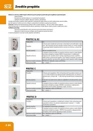
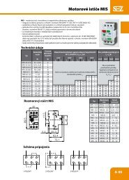
AccessoriesProduct definitionCLAMP-TYPE TERMINALDirect - connection terminal – clamp - type terminal for Cu conductor and ribbon conductor connection.V-TERMINAL CLAMPDirect - connection terminal – V - terminal clamp for Cu conductor and Al conductor connection.OUTPUT INDICATOROutput indicator for indication of connected or disconnected state.MECHANICAL FUSE MONITORIn conjunction with <strong>LV</strong> <strong>HRC</strong> <strong>fuse</strong> – links with striker, the mechanical <strong>fuse</strong> monitor indicates <strong>fuse</strong> failure. Thestrikeractuates a micro<strong>switch</strong> when the <strong>fuse</strong>-link is disconnected. The micro<strong>switch</strong> then passes the failure signal to a controlcentre.OVERREACHING PROTECTIONThe upper and lower latch - on overreaching protection covers the connection contacts or cable lugs or bare protrudingconductors. The live parts are covered probe-safe.HANDLE PROTECTION FOR BLADESThe overreaching protection for the contact blades of the <strong>LV</strong> <strong>HRC</strong> <strong>fuse</strong> - links ismovably fitted in the front plate. Whenthe front plate is swung out, the overreaching protection is swung out from the front plate on the face, thus coveringthe contact blades of the <strong>fuse</strong> – links probe - safe.SHROUDThe latch-on covering panels cover the <strong>switch</strong>board apertures and ensure IP30 protection in the connected state.DIN RAIL FIXING PARTSThe retrofittable DIN rail fixing parts consist of two hang - up hooks and a slide. They allow <strong>size</strong> 00 <strong>LV</strong> <strong>HRC</strong> <strong>fuse</strong> <strong>switch</strong>– <strong>disconnectors</strong> to be fixed on two standard rails in accordance with EN 50022 with 100mm to 150mm distancebetween rail centres.PROTECTIVE COVER INTERLOCKThe protective cover interlock can be latched into the protective covers. It is interlocked with the basic frame by a 90°turn of a screwdriver.ELECTRONIC FUSE MONITORINGThe electronic <strong>fuse</strong> monitoring feature ES00 can be used in the voltage range AC 400V to AC 690V. It isself-powered and the infeed can be at either end.ApplicationsDirect-connection terminals replace cable lugs. They are suitable for Cu conductors, ribbon conductors and Cu busbars.Mechanical <strong>fuse</strong> monitors are used for remote indication of <strong>fuse</strong> failure. The overreaching protection prevents accidentalcontact with live parts. The overreaching protection for the contact blades of the <strong>LV</strong> <strong>HRC</strong> <strong>fuse</strong>-links is used for supplyfrombelow. It prevents accidental contact with the live contact blades of the <strong>fuse</strong> - links when the front plate is not entirelyclosed. Covering panels are used for panel mounting. They ensure complete covering of the panel cutouts and thus IP30protection. The DIN rail fixing parts for <strong>size</strong> 00 <strong>LV</strong> <strong>HRC</strong> <strong>fuse</strong> <strong>switch</strong> - <strong>disconnectors</strong> are used in control cabinets in combinationwith miniature circuit - breakers and in distribution systems in which only standard rails in accordance with EN 50022are integrated. Protective cover interlocks ensure that the covers can only be removed by a tool, thus complying with BGVA2 requirements.C 15
AccessoriesFlat termination Std.P TypeSize 00 3 F-LTL00-M8Size 1 3 F-LTL1-M10Size 2 3 F-LTL2-M10Size 3 3 F-LTL3-M10Clamp-type terminal Std.P TypeSize 00/1,5-70 mm² Cu (also for GU00) 3 S00-ZSize 1 3 S1Size 2 3 S2Size 3 3 S3V-terminal clamp Std.P TypeSize 00/10-70 mm² Al/Cu 3 P0070-ZSize 1 3 P1Size 2 3 P2Size 3 3 P3Handle protection 3-pole, surface mounting Std.P TypeSize 00, top or bottom 1 LTL00-3Size 1, top 1 GO-LTL1-3Size 2, top 1 GO-LTL2-3Size 3, top (also for busbar mounting) 1 GO-LTL3-3Size 1, bottom 1 GU-LTL1-3Size 2, bottom 1 GU-LTL2-3Size 3, bottom, (also for busbar mounting) 1 GU-LTL3-3Handle protection 3-pole, busbar mounting Std.P TypeSize 00, top, system-measurement 195mmGO-LTL00-3/195Size 00, top, extended, system-measurement 230mm 1 GOV-LTL00-3/230Size 2, topGOV-LTL2-3Size 1, top, extendedGOV-LTL1-3Size 00, bottom, system-measurement 195mmGU-LTL00-3/195Size 2, bottomGUV-LTL2-3Size 00, bottom, extended, system-measurement 230mm 1 GUV-LTL00-3/230Size 1, bottom, extendedGUV-LTL1-3Size 2, extension top/bottomGV-LTL2-3Handle protection 1-pole, surface- and busbar mounting Std.P TypeSize 00, top or bottom 1 GOU-LTL00-1Size 1, top or bottom 1 GOU-LTL1-1Size 3, top or bottom 1 GOU-LTL3-1C 16
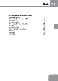
Dimensional drawingsLTL00-1/9LTL1-1/9, LTL3-1/9Type A B C D E F G H ILTL1-1/9 69 230 317 68 119 16,5 115 177 25LTL3-1/9 91 270 430 96 147 9 135 220,5 30,5C 17
Dimensional drawingsLTL4A-1x/1250(1600)/8BC1250 A 270 3151600 A 311 339LTL00-2/9C 18
Dimensional drawingsLTL1-2/9, LTL3-2/9Type A B C D E F G H ILTL1-2/9 138 230 317 68 123,5 23 115 177 25LTL3-2/9 182 270 430 96 151,5 15,5 135 220,5 30,5LTL...-3/9, LTL...-3/9/ES00Type A B C D E F G H I K L L1LTL00-3/9 105,5 149 220 45 86 20,5 74,5 120 17 33 116 126LTL1-3/9 184 230 317 68 119 16,5 115 177 25 58 149 159LTL2-3/9 210 256 397 81 133 16,5 128 205 25 66 163 173LTL3-3/9 254 270 430 96 147 9 135 220,5 30,5 82 177 187C 19
Dimensional drawingsLTL4A-3x(3)/.../8/(Q)BC1250 A 270 3151600 A 311 339LTL00-4/9C 20
Dimensional drawingsS00, S1, S2, S3Type A B C D E FS00 25 15 15 M5 Max. 15 5,5S1 37 20 25 M6 Max. 28 6,5S2 42 22 28 M8 Max. 30 8,5S3 50 25 30 M8 Max. 30 8,5P1, P2, P3, P12, P22, P32C 22Type A B C D E FP0070 25 15 15 M5 Max. 25 5,5P0095 29 15 18 M5 Max. 28 5, 5P1 37 20 25 M6 Max. 30 6,5P12 37 20 25 M6 Max. 42 6,5P2 42 22 28 M8 Max. 40 8,5P22 42 22 28 M8 Max. 55 8,5P3 50 25 30 M8 Max. 44 8,5P32 50 25 30 M8 Max. 66 8,5