Residual current circuit breakers PFB and PCHB - SEZ Krompachy
Residual current circuit breakers PFB and PCHB - SEZ Krompachy
Residual current circuit breakers PFB and PCHB - SEZ Krompachy

You also want an ePaper? Increase the reach of your titles
YUMPU automatically turns print PDFs into web optimized ePapers that Google loves.
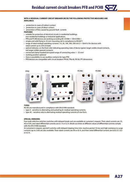
<strong>Residual</strong> <strong>current</strong> <strong>Residual</strong> <strong>circuit</strong> <strong>current</strong> <strong>breakers</strong> <strong>circuit</strong> <strong>breakers</strong> <strong>PFB</strong> <strong>PFB</strong> <strong>and</strong> <strong>and</strong> <strong>PCHB</strong>WITH A RESIDUAL CURRENT CIRCUIT BREAKER (RCCB) THE FOLLOWING PROTECTIVE MEASURES AREAVAILABLE:• protection in cases of indirect contact• protection in cases of direct contact• prevention of fires caused by ground-fault <strong>current</strong>sFEATURES• suitable for protection of electrical <strong>circuit</strong>s in residential buildings,non-residential buildings or industrial applications• <strong>PFB</strong> <strong>and</strong> <strong>PCHB</strong> devices are working according IEC 61008-1 / EN 61008-1• simple <strong>and</strong> solid fixing to 35 mm mounting rail in compliance to EN 6071• range of rated residual operating <strong>current</strong>s I 10, 30, 100, 300, 500 mA (I = 10mA is for devices withrated <strong>current</strong> up to 25A include)• optical indicator, on the front side indicating operating state of device (green target visible closed contacts,red target visible opened contacts)• connected clamp headed/stirrupted range of connecting wires 1 - 25 mm 2• working position optional• there is possibility to use auxiliary contacts for type <strong>PFB</strong>• <strong>PFB</strong> devices are compatible with <strong>circuit</strong> <strong>breakers</strong> PR 60, PRe 60, RV 60, PFI dimensions<strong>PFB</strong>2 <strong>PFB</strong>4 <strong>PCHB</strong>2 <strong>PCHB</strong>4TYPESRCCBs are manufactured in compliance with EN 61008 st<strong>and</strong>ard:• type A - sensitive to alternating <strong>and</strong> pulsating dc residual operating <strong>current</strong>s.• type AC - sensitive only to alternating residual operating <strong>current</strong>s of sine form.SPECIAL VERSIONSFour-pole selective switches (switches with delayed break-out) are available at customer‘s request. Their rated <strong>current</strong>s are 25,40 or 63A, <strong>and</strong> rated differential <strong>current</strong>s are 0,1 A or 0,3 A. Break out times at different values of differential <strong>current</strong>s complywith the EN 61008 st<strong>and</strong>ard.At customers‘s request, special K switches with delayed tripping time (min. inactive period 10 ms) <strong>and</strong> high resistance to surge<strong>current</strong>s (up to 3 kA) are also available. Their rated <strong>current</strong>s are 40 or 63 A, <strong>and</strong> their rated differential <strong>current</strong>s are 0,03; 0,1; 0,3or 0,5 A.A27
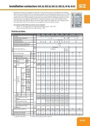
Technical data<strong>Residual</strong> <strong>current</strong> <strong>current</strong> <strong>circuit</strong> <strong>circuit</strong> <strong>breakers</strong> <strong>breakers</strong> <strong>PFB</strong> <strong>and</strong> <strong>PCHB</strong> <strong>PFB</strong> <strong>and</strong> <strong>PCHB</strong>Versions <strong>PFB</strong>2 <strong>PFB</strong>4 <strong>PCHB</strong>2 <strong>PCHB</strong>4TypesA, ACNumber of poles 2 4 2 4Rated <strong>current</strong> I nA 16 - 63 16 - 63 16 - 100 16 - 100Rated residual operating <strong>current</strong> I DnA 0,01 - 0,5 0,03 - 0,5 0,01 - 0,5 0,03 - 0,5Rated voltage U nV 230 230/400 230 230/400Rated frequency Hz 50 50 50/60 50/60Rated res. making <strong>and</strong>breaking capacity I mI Δm630 630 800; 1000 for In=100ARated res. making <strong>and</strong>breaking capacityI ∆mMax. conventionalback-up fuses GL I nA 63; 80 for In=63 <strong>and</strong> 80A; 100 for In=100ARated conditionalshort-<strong>circuit</strong> <strong>current</strong> I ncA 10000; 6000 for In=100AProtection degreeIP 20; IP40 after installationMounting positionoptionalAmbient temperature °C from -25°C to +40°CWeight g 250 435 230 390Terminal capacity mm 2 1 to 25 1 to 35Accessories auxiliary <strong>and</strong> signal contacts sealing coversDimensional drawings of <strong>PFB</strong> <strong>and</strong> <strong>PCHB</strong>69694535<strong>PFB</strong> 2 <strong>PFB</strong> 4696044 5,5<strong>PCHB</strong> 4 <strong>PCHB</strong> 2Contacts scheme<strong>PFB</strong> - 2 <strong>PFB</strong> - 4<strong>PCHB</strong> - 2 <strong>PCHB</strong> - 4A28
<strong>Residual</strong> <strong>current</strong> <strong>Residual</strong> <strong>circuit</strong> <strong>current</strong> <strong>breakers</strong> <strong>circuit</strong> <strong>breakers</strong> <strong>PFB</strong> <strong>PFB</strong> <strong>and</strong> <strong>and</strong> <strong>PCHB</strong><strong>PFB</strong> - 22 pole versionOrdering Nr.Type AType ACI ∆n= 0,01 A<strong>PFB</strong>2 - 16/0,01 0090660 0090660AC<strong>PFB</strong>2 - 25/0,01 0090661 0090661ACI ∆n= 0,03 A<strong>PFB</strong>2 - 16/0,03 0090662 0090662AC<strong>PFB</strong>2 - 25/0,03 0090663 0090663AC<strong>PFB</strong>2 - 40/0,03 0090664 0090664AC<strong>PFB</strong>2 - 63/0,03 0090665 0090665ACI ∆n= 0,1 A<strong>PFB</strong>2 - 16/0,1 0090666 0090666AC<strong>PFB</strong>2 - 25/0,1 0090667 0090667AC<strong>PFB</strong>2 - 40/0,1 0090668 0090668AC<strong>PFB</strong>2 - 63/0,1 0090669 0090669ACI ∆n= 0,3 A<strong>PFB</strong>2 - 16/0,3 0090670 0090670AC<strong>PFB</strong>2 - 25/0,3 0090671 0090671AC<strong>PFB</strong>2 - 40/0,3 0090672 0090672AC<strong>PFB</strong>2 - 63/0,3 0090673 0090673ACI ∆n= 0,5 A<strong>PFB</strong>2 - 16/0,5 0090674 0090674AC<strong>PFB</strong>2 - 25/0,5 0090675 0090675AC<strong>PFB</strong>2 - 40/0,5 0090676 0090676AC<strong>PFB</strong>2 - 63/0,5 0090677 0090677AC<strong>PFB</strong> - 44 pole versionOrdering Nr.Type AType ACI ∆n= 0,03 A<strong>PFB</strong>4 - 16/0,03 0090682 0090682AC<strong>PFB</strong>4 - 25/0,03 0090683 0090683AC<strong>PFB</strong>4 - 40/0,03 0090684 0090684AC<strong>PFB</strong>4 - 63/0,03 0090685 0090685ACI ∆n= 0,1 A<strong>PFB</strong>4 - 16/0,1 0090686 0090686AC<strong>PFB</strong>4 - 25/0,1 0090687 0090687AC<strong>PFB</strong>4 - 40/0,1 0090688 0090688AC<strong>PFB</strong>4 - 63/0,1 0090689 0090689ACI ∆n= 0,3 A<strong>PFB</strong>4 - 16/0,3 0090690 0090690AC<strong>PFB</strong>4 - 25/0,3 0090691 0090691AC<strong>PFB</strong>4 - 40/0,3 0090692 0090692AC<strong>PFB</strong>4 - 63/0,3 0090693 0090693ACI ∆n= 0,5 A<strong>PFB</strong>4 - 16/0,5 0090694 0090694AC<strong>PFB</strong>4 - 25/0,5 0090695 0090695AC<strong>PFB</strong>4 - 40/0,5 0090696 0090696AC<strong>PFB</strong>4 - 63/0,5 0090697 0090697AC<strong>PCHB</strong> - 22 pole version<strong>PCHB</strong>2 - 16/0,01<strong>PCHB</strong>2 - 25/0,01<strong>PCHB</strong>2 - 16/0,03<strong>PCHB</strong>2 - 25/0,03<strong>PCHB</strong>2 - 40/0,03<strong>PCHB</strong>2 - 63/0,03<strong>PCHB</strong>2 - 80/0,03<strong>PCHB</strong>2 - 100/0,03<strong>PCHB</strong>2 - 16/0,1<strong>PCHB</strong>2 - 25/0,1<strong>PCHB</strong>2 - 40/0,1<strong>PCHB</strong>2 - 63/0,1<strong>PCHB</strong>2 - 80/0,1<strong>PCHB</strong>2 - 100/0,1<strong>PCHB</strong>2 - 16/0,3<strong>PCHB</strong>2 - 25/0,3<strong>PCHB</strong>2 - 40/0,3<strong>PCHB</strong>2 - 63/0,3<strong>PCHB</strong>2 - 80/0,3<strong>PCHB</strong>2 - 100/0,3<strong>PCHB</strong> - 44 pole version<strong>PCHB</strong>4 - 25/0,03<strong>PCHB</strong>4 - 40/0,03<strong>PCHB</strong>4 - 63/0,03<strong>PCHB</strong>4 - 80/0,03<strong>PCHB</strong>4 - 100/0,03<strong>PCHB</strong>4 - 25/0,1<strong>PCHB</strong>4 - 40/0,1<strong>PCHB</strong>4 - 63/0,1<strong>PCHB</strong>4 - 80/0,1<strong>PCHB</strong>4 - 100/0,1<strong>PCHB</strong>4 - 25/0,3<strong>PCHB</strong>4 - 40/0,3<strong>PCHB</strong>4 - 63/0,3<strong>PCHB</strong>4 - 80/0,3<strong>PCHB</strong>4 - 100/0,3<strong>PCHB</strong>4 - 40/0,5I ∆n= 0,01 AI ∆n= 0,03 AI ∆n= 0,1 AI ∆n= 0,3 AI ∆n= 0,03 AI ∆n= 0,1 AI ∆n= 0,3 AI ∆n= 0,5 AOrdering Nr.Type A<strong>PCHB</strong>2/721011<strong>PCHB</strong>2/722011<strong>PCHB</strong>2/721031<strong>PCHB</strong>2/722031<strong>PCHB</strong>2/724031<strong>PCHB</strong>2/726031<strong>PCHB</strong>2/728031<strong>PCHB</strong>2/7210031<strong>PCHB</strong>2/721101<strong>PCHB</strong>2/722101<strong>PCHB</strong>2/724101<strong>PCHB</strong>2/726101<strong>PCHB</strong>2/728101<strong>PCHB</strong>2/7210101<strong>PCHB</strong>2/721301<strong>PCHB</strong>2/721301<strong>PCHB</strong>2/724301<strong>PCHB</strong>2/726301<strong>PCHB</strong>2/728301<strong>PCHB</strong>2/7210301Ordering Nr.Type A<strong>PCHB</strong>4/742031<strong>PCHB</strong>4/744031<strong>PCHB</strong>4/746031<strong>PCHB</strong>4/748031<strong>PCHB</strong>4/7410031<strong>PCHB</strong>4/742101<strong>PCHB</strong>4/744101<strong>PCHB</strong>4/746101<strong>PCHB</strong>4/748101<strong>PCHB</strong>4/7410101<strong>PCHB</strong>4/742301<strong>PCHB</strong>4/744301<strong>PCHB</strong>4/746301<strong>PCHB</strong>4/748301<strong>PCHB</strong>4/7410301<strong>PCHB</strong>4/744501A29
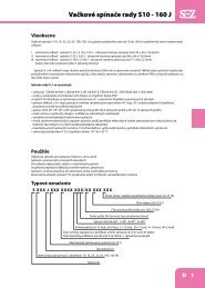
<strong>Residual</strong> <strong>current</strong> <strong>circuit</strong> <strong>breakers</strong> <strong>PFB</strong> <strong>and</strong> <strong>PCHB</strong>Instantaneous tripping characteristics <strong>PCHB</strong>BASIC TERMS AND SYMBOLS•Rated residual <strong>current</strong> I ∆nis the value of residual <strong>current</strong> I ∆nspecified by the manufacturer at which the residual <strong>current</strong> <strong>circuit</strong>breaker must switch out under specified conditions. Alternatingresidual <strong>current</strong> must release the residual <strong>current</strong> <strong>circuit</strong>breaker within (0.5 ÷ 1) I ∆n•Rated conditional short-<strong>circuit</strong> <strong>current</strong> I nc– short-<strong>circuit</strong>strength. The function <strong>and</strong> design principle does not allow forthe residual <strong>current</strong> <strong>circuit</strong> breaker use for protection againstshort-<strong>circuit</strong>. For <strong>circuit</strong> protection it is necessary to use a <strong>circuit</strong>breaker or a fuse. These elements cut the short-<strong>circuit</strong>ed<strong>circuit</strong> safely off . The residual <strong>current</strong> <strong>circuit</strong> breaker must onlywithst<strong>and</strong> the through-going short-<strong>circuit</strong> <strong>current</strong>. The amplitudeof the maximum through <strong>current</strong> is defined as rated conditionalshort-<strong>circuit</strong> <strong>current</strong> I nc. The short-<strong>circuit</strong> strength is thenexpressed by the <strong>current</strong> Inc. For example, on the rating plate, I nc= 10 kA is expressed by the following symbol:•<strong>Residual</strong> <strong>current</strong> <strong>circuit</strong> breaker – type AC – reacts to sine--wave residual <strong>current</strong> – it is used in conventional AC networks.•<strong>Residual</strong> <strong>current</strong> <strong>circuit</strong> breaker – type A – reacts to sine-wavealternating <strong>and</strong> pulsating direct residual <strong>current</strong>s - it is used inconventional AC networks <strong>and</strong> the networks with phase powerregulation etc.•<strong>Residual</strong> <strong>current</strong> <strong>circuit</strong> breaker – type G – special residual<strong>current</strong> <strong>circuit</strong> breaker reducing the number of undesirable releases.It is mainly installed before the devices causing short-time(up to 10 ms) stray <strong>current</strong>s.Identifi cation: GRelease delay: 10 ms•<strong>Residual</strong> <strong>current</strong> <strong>circuit</strong> breaker – type S – special residual<strong>current</strong> <strong>circuit</strong> breaker, which is mainly intended for selectiveswitching of residual <strong>current</strong> <strong>circuit</strong> <strong>breakers</strong> <strong>and</strong> reduction ofundesirable releases. It is installed before the devices causingshort-time (up to 40 ms) stray <strong>current</strong>s. Identification: S releasedelay: 40 ms Selective (discriminating) switching means that ifthe residual <strong>current</strong> <strong>circuit</strong> <strong>breakers</strong> are connected in series, onlythe device in which <strong>circuit</strong> a failure occurs will release. More specifically,only the device in which the release residual <strong>current</strong>appears due to a failure in the protected <strong>circuit</strong> will release. Theadvantage consists in maintaining the power supply in the other<strong>circuit</strong>s not aff ected by the failure. Such function of the protected<strong>circuit</strong> is achieved by connection of the selective residual<strong>current</strong> <strong>circuit</strong> breaker before the st<strong>and</strong>ard or G type residual<strong>current</strong> <strong>circuit</strong> breaker, with the following ratio of rated residual<strong>current</strong>s: I ∆n S≥ 3 x I ∆n -,GI ∆nSrated residual of the selective residual<strong>current</strong> <strong>circuit</strong> breaker I ∆n -,Gmaximum rated residual <strong>current</strong> of Gtype residual <strong>current</strong> <strong>circuit</strong> breaker. The main reason of selectiveswitching is higher time delay of the selective residual <strong>current</strong><strong>circuit</strong> <strong>breakers</strong> in releasing (compared to st<strong>and</strong>ard or G typeones).A30