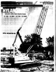
Linkbelt-LS208H2-Spec - Rawalwasia
Linkbelt-LS208H2-Spec - Rawalwasia
Linkbelt-LS208H2-Spec - Rawalwasia

Create successful ePaper yourself
Turn your PDF publications into a flip-book with our unique Google optimized e-Paper software.
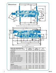
WIRE ROPE CAPACITY<br />
Parts 1” 5/8”<br />
of<br />
Line<br />
Type<br />
Type<br />
Type<br />
Type<br />
Type<br />
“M” “DB” “RB” “ZB” “WB”<br />
1 29,500 29,500 22,700 * 11,000 13,650 *<br />
Notes<br />
LIFTOFF CAPABILITIES<br />
Over End / Over Side<br />
(Gantry In Raised Position)<br />
Counterweight<br />
(Side Frames) Maximum Boom Maximum Boom + Jib<br />
2 59,000 59,000 45,500 22,000 27,310 Capacities shown<br />
are in pounds and<br />
3 88,600 88,600 68,200 33,000 40,970 working loads must<br />
not exceed the<br />
4 118,100 118,100 91,000 44,000 54,620 ratings on the<br />
capacity charts in<br />
5 147,700 147,700 113,800 55,000 68,280 this Crane Rating<br />
Manual.<br />
6 177,200 177,200 136,500 66,000 81,940 Study Operator’s<br />
Manual for wire rope<br />
7 206,800 206,800 159,300 77,000 95,600 inspection<br />
procedures.<br />
8 236,300 236,300 182,000 88,000 109,250<br />
LBCE<br />
Type<br />
Description<br />
DB 6 x 26 (6 x 19 Class) – Warrington Seale – Extra Improved Plow Steel –<br />
Preformed – Right Lay – Regular Lay – I.W.R.C.<br />
RB* 19 x 19 Rotation Resistant– Extra Extra Improved Plow Steel – Preformed –<br />
Right Lay – Regular Lay. Swaged – S.F. = 5:1<br />
ZB 36 x 7 Class – Non–Rotating – Extra Improved Plow Steel – Right Lay –<br />
Regular Lay – S.F. = 5:1<br />
WB*<br />
M<br />
8 Strand – Regular Lay<br />
6 X 19 Class – Extra Improved Plow Steel – Lang Lay<br />
* Use of swivel end with 1 part of line is not recommended.<br />
NO<br />
(RETRACTED)<br />
NO<br />
(EXTENDED)<br />
A<br />
(RETRACTED)<br />
A<br />
(EXTENDED)<br />
A<br />
(EXTENDED)<br />
See Note 4<br />
AB<br />
(EXTENDED)<br />
See Note 5<br />
(ft)<br />
(ft)<br />
80 N/A<br />
100 N/A<br />
110 N/A<br />
130 N/A<br />
150<br />
See Note 4<br />
150<br />
N/A<br />
140 + 60<br />
150 + 30<br />
Note:<br />
Over Idler End<br />
WORKING AREAS<br />
See Note<br />
Longitudinal<br />
Of Crawler<br />
Idler Sprocket<br />
360<br />
Over Side<br />
Boom<br />
Drive Sprocket<br />
Over Side<br />
Center Of<br />
Rotation<br />
See<br />
Note<br />
1. These Lines Determine The Limiting Position Of Any Load For<br />
Operation Within Working Areas Indicated.<br />
Over Drive End<br />
NOTES:<br />
1. For maximum stability, booms should be erected or<br />
lowered over the end with no load –hook block on<br />
ground.<br />
2. Crane on firm and level surface.<br />
3. Gantry pins must be installed when the gantry is in the<br />
raised position.<br />
4. For 140 ft. or 150 ft. boom (side frame extended) with A<br />
counterweight only – Adequate blocking must be<br />
placed under both treadmember sprockets (or idler<br />
rollers) at the end that the boom is to be lifted off to pre–<br />
vent rocking. Liftoff over end only with 140 ft. and 150<br />
ft. boom. The ramps supplied with the crane are con–<br />
sidered to be adequate blocking.<br />
5. For 140 ft. + 60 ft. or 150 ft. + 30 ft. (side frame<br />
extended) with AB counterweight only – adequate<br />
block–ing must be placed under both treadmember<br />
sprockets (or idler rollers) at the end that the boom is to<br />
be lifted off to prevent rocking. Liftoff over end only with<br />
140 ft. + 60 ft. and 150 ft. + 30 ft. boom. The ramps<br />
supplied with the crane are considered to be adequate<br />
blocking.<br />
<br />
LS–208H