Q71B 230V Control Board Swing Gate – Double Leaf ... - Gate Motors
Q71B 230V Control Board Swing Gate – Double Leaf ... - Gate Motors
Q71B 230V Control Board Swing Gate – Double Leaf ... - Gate Motors

You also want an ePaper? Increase the reach of your titles
YUMPU automatically turns print PDFs into web optimized ePapers that Google loves.
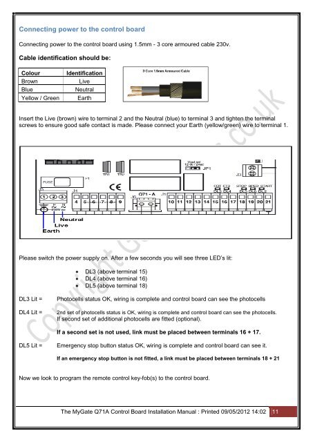
Connecting power to the control board<br />
Connecting power to the control board using 1.5mm - 3 core armoured cable 230v.<br />
Cable identification should be:<br />
Colour<br />
Brown<br />
Blue<br />
Yellow / Green<br />
Identification<br />
Live<br />
Neutral<br />
Earth<br />
Insert the Live (brown) wire to terminal 2 and the Neutral (blue) to terminal 3 and tighten the terminal<br />
screws to ensure good safe contact is made. Please connect your Earth (yellow/green) wire to terminal 1.<br />
Please switch the power supply on. After a few seconds you will see three LED’s lit:<br />
DL3 (above terminal 15)<br />
DL4 (above terminal 16)<br />
DL5 (above terminal 18)<br />
DL3 Lit =<br />
DL4 Lit =<br />
Photocells status OK, wiring is complete and control board can see the photocells<br />
2nd set of photocells status is OK, wiring is complete and control board can see the photocells.<br />
If second set of additional photocells are fitted (optional).<br />
If a second set is not used, link must be placed between terminals 16 + 17.<br />
DL5 Lit =<br />
Emergency stop button status OK, wiring is complete and control board can see it.<br />
If an emergency stop button is not fitted, a link must be placed between terminals 18 + 21<br />
Now we look to program the remote control key-fob(s) to the control board.<br />
The My<strong>Gate</strong> Q71A <strong>Control</strong> <strong>Board</strong> Installation Manual : Printed 09/05/2012 14:02 11