Q71B 230V Control Board Swing Gate – Double Leaf ... - Gate Motors
Q71B 230V Control Board Swing Gate – Double Leaf ... - Gate Motors
Q71B 230V Control Board Swing Gate – Double Leaf ... - Gate Motors

You also want an ePaper? Increase the reach of your titles
YUMPU automatically turns print PDFs into web optimized ePapers that Google loves.
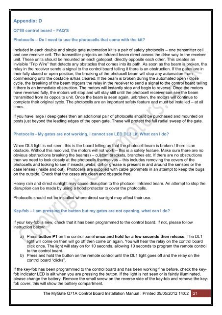
Appendix: D<br />
<strong>Q71B</strong> control board <strong>–</strong> FAQ’S<br />
Photocells <strong>–</strong> Do I need to use the photocells that come with the kit<br />
Included in each double and single gate automation kit is a pair of safety photocells <strong>–</strong> one transmitter cell<br />
and one receiver cell. The transmitter projects an Infrared beam direct across the drive way to the receiver<br />
unit. These units should be mounted on each gatepost, directly opposite each other. This creates an<br />
invisible “Trip Wire” that detects any obstacles that comes into its path. As soon as the beam is broken, the<br />
relay in the receiver sends a signal to the control board telling it there is an obstruction. If the gates are in<br />
their fully closed or open position, the breaking of the photocell beam will stop any automation from<br />
commencing until the obstacle is/has cleared. If the beam is broken during the automated open / close<br />
cycle, the breaking of the beam triggers the relay in the receiver to send a signal to the control board telling<br />
it there is an immediate obstruction. The motors will instantly stop and begin to reverse. Once the motors<br />
have reversed fully, the motors will stop and will stay still until the photocell receiver can see the beam<br />
transmitted from its opposite unit. Once the beam is seen again, unbroken, the motors will continue to<br />
complete their original cycle. The photocells are an important safety feature and must be installed <strong>–</strong> at all<br />
times.<br />
If you have large / deep gates then an additional pair of photocells should be purchased and mounted on<br />
posts just beyond the leading edges of the open gate. These will protect the full radial sweep of the gate.<br />
Photocells - My gates are not working, I cannot see LED DL3 Lit. What can I do<br />
When DL3 light is not seen, this is the board telling us that the photocell beam is broken / there is an<br />
obstacle. Without this resolved, the motors will not work <strong>–</strong> this is a safety feature. Make sure there are no<br />
obvious obstructions breaking the beam(s) <strong>–</strong> custom brackets, branches etc. If there are no obstructions<br />
then we need to look closely at the photocells themselves <strong>–</strong> this includes removing the covers of the<br />
photocells and looking to see if insects, webs, dirt or grease is present in and around the sensors or the<br />
case lenses (inside and out). Photocells are supplied with cable grommets in an attempt to keep the bugs<br />
on the outside. Check that the cases are clean and obstacle free.<br />
Heavy rain and direct sunlight may cause disruption to the photocell Infrared beam. An attempt to stop the<br />
disruption can be made by using a hood protector to cover the photocells.<br />
Photocells should not be installed where direct sunlight may affect their use.<br />
Key-fob <strong>–</strong> I am pressing the button but my gates are not opening, what can I do<br />
If your key-fob is new, check that it has been programmed to the control board. If not, please follow<br />
instruction below:<br />
a) Press button P1 on the control panel once and hold for a few seconds then release. The DL1<br />
light will come on then will go off then come on again. You will hear the relay on the control board<br />
click once. The light will stay on for 10 seconds, allowing 10 seconds to program the remote control<br />
to the control board.<br />
b) Press and hold the button on the remote control until the DL1 light goes off and the relay on the<br />
control board “clicks”.<br />
If the key-fob has been programmed to the control board and has been working fine before, check the keyfob<br />
indicator LED is alit when you are pressing the button. If the light is not seen or is faintly illuminated,<br />
please change the battery. Remove the small screw on the reverse side of the key-fob and remove the keyfob<br />
cover, this will show the battery compartment.<br />
The My<strong>Gate</strong> Q71A <strong>Control</strong> <strong>Board</strong> Installation Manual : Printed 09/05/2012 14:02 21