

View PDF - Bender
View PDF - Bender
View PDF - Bender

You also want an ePaper? Increase the reach of your titles
YUMPU automatically turns print PDFs into web optimized ePapers that Google loves.
4<br />
T M<br />
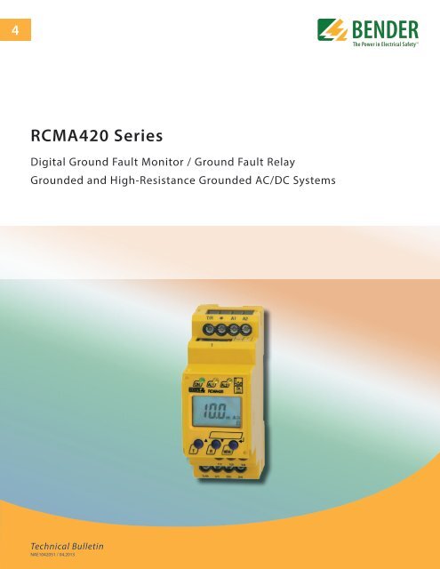
RCMA420 Series<br />
Digital Ground Fault Monitor / Ground Fault Relay<br />
Grounded and High-Resistance Grounded AC/DC Systems<br />
Technical Bulletin<br />
NAE1042051 / 04.2013
BENDER Inc. • 700 Fox Chase, Coatesville PA 19320 • Ph: 800-356-4266 / 610-383-9200 • Fax: 610-383-7100<br />
Ground fault monitor RCMA420<br />
Ground Fault Monitor / Ground Fault Relay<br />
for Grounded AC, DC, and AC/DC Systems<br />
Description<br />
The RCMA420 monitors for ground faults in grounded and high-resistance grounded AC<br />
(both single- and three-phase), DC, and mixed AC/DC systems. The RCMA420 is specially<br />
designed to provide advanced warning of developing ground faults without the problems<br />
associated with high sensitivity nuisance tripping.<br />
A digital LCD screen displays real-time measurements of the system's ground fault current.<br />
Two separately adjustable SPDT contacts allow for information transmission (such as to a<br />
PLC) or power interruption (such as through a contactor or shunt trip breaker).<br />
Since the values are measured with measuring current transformers, the device is nearly<br />
independent of the load current and the nominal voltage of the system.<br />
RCMA420<br />
Features<br />
• Ground fault monitoring for AC, DC, and<br />
mixed AC/DC systems<br />
• True RMS value measurement (AC + DC)<br />
• Main alarm value, adjustable 10…500 mA<br />
• Separate prewarning alarm value, adjustable<br />
to 50…100 % of the main alarm<br />
• Frequency range 0…2000 Hz<br />
• 3 separately adjustable time delays: star<br />
tup, response, and release<br />
• LCD screen with real-time value display<br />
• Latching or non-latching operating mode<br />
• CT connection monitoring<br />
• Power On LED, LED Alarm 1 / 2<br />
• TEST / RESET button, internal / external<br />
• Two separate voltage-free SPDT contacts<br />
• Selectably operates normally energized<br />
or normally de-energized<br />
• Continuous self monitoring<br />
• Password protection for device settings<br />
• Sealable transparent cover<br />
• Two-module enclosure (36 mm)<br />
• Conforms to RoHS<br />
Approvals<br />
Applications<br />
• Ground fault detection in single- or three-phase AC systems<br />
• Ground fault detection in pure DC or mixed AC/DC systems<br />
• Motors and motor control systems<br />
• Systems with variable frequency drives (VFDs)<br />
• Battery backup systems and other pure DC systems<br />
Function<br />
Once the supply voltage U S is applied, the startup delay ("t") activates. Alarms during this delay<br />
will not cause the RCMA420 to switch over the contacts.<br />
Measurements of the system's ground fault current are taken via an external current transformer.<br />
For AC, all phases (including the neutral if one exists) are placed through the current<br />
transformer. For DC, both legs are placed through the current transformer. The measured<br />
value is indicated in real-time on the device's LCD display.<br />
If the measured value exceeds one or both response values, the respective response delays<br />
t on 1 /2 activate. If the ground fault still exists after the response delays expire, the respective<br />
contacts switch over and the alarm LEDs activate. If the device is set to non-latching mode<br />
and the ground fault clears, the alarms will clear after the set release time "t off" expires. If the<br />
device is set to latching mode, the alarms will not clear until the device is reset manually or<br />
the supply voltage is lost. The TEST function allows for an internal operation testing of the<br />
device. The device's easy-to-use onboard menu manages all settings via the detailed LCD<br />
screen. An optional password protection setting protects unauthorized users from changing<br />
settings.<br />
Connection monitoring<br />
The connections between the device and the external current transformer are continuously<br />
monitored. If the device detects a connection error, the CT connection monitoring alarm will<br />
activate, and the contacts will switch over without delay. After the connection error is<br />
cleared, the device will reset based on its latching/non-latching setting.<br />
2
Front display and operating elements<br />
Wiring diagram<br />
1<br />
2<br />
3<br />
4<br />
2<br />
1<br />
4 5<br />
5<br />
6 7<br />
1 - Power “ON” LED (green): Illuminates when power is received<br />
to the unit. Flashes when the current transformer connectionalarm<br />
is active.<br />
2 - Alarm LED “AL1” (yellow): Alarm 1, illuminates when the set<br />
response value I Δn1 has been exceeded. Flashes when the<br />
current transformer connection alarm is active.<br />
3 - Alarm LED “AL2” (yellow): Alarm 2, illuminates when the set<br />
response value I Δn2 has been exceeded. Flashes when the current<br />
transformer connection alarm is active.<br />
4 - Multi-functional LCD display<br />
5 - TEST button: Activates self-test<br />
Arrow up key: Scrolls up inside device's menu<br />
6 - RESET button: Resets device<br />
Arrow down key: Scrolls down inside device's menu<br />
7 - MENU key: Activates device's internal menu<br />
Enter key: Confirm change inside device's menu<br />
Escape key (held > 1.5 s): Goes back a step inside menu<br />
5<br />
3<br />
4<br />
1 - External supply voltage used to power device<br />
a 6 A fuse recommended for internal short circuit protection<br />
2 - Connection to external current transformer. For AC, all pha<br />
ses (including a neutral if one exists) are placed through. For<br />
DC, both legs are placed through.<br />
3 - Alarm relay K1: I Δn1 (prewarning).<br />
4 - Alarm relay K2: alarm I Δn2 (alarm).<br />
5 - Combined TEST and RESET button:<br />
short depress (< 1.5 s) = RESET,<br />
long depress (> 1.5 s) = TEST.<br />
Note: Do not route the ground conductor through the measuring<br />
current transformer when also routing the power conductors!<br />
3
Wiring diagram: External current transformer<br />
Dimensions<br />
Dimensions in inches (mm)<br />
2.78”<br />
(70.5)<br />
1.87”<br />
(47.5)<br />
1.42” (36)<br />
1.22” (31.1)<br />
2.66” (67.5)<br />
1.77” (45)<br />
3.54” (90)<br />
Ordering information: RCMA420 (standard models)<br />
Type<br />
Response Frequency Supply<br />
range I Δn range voltage U S*<br />
Ordering No.<br />
DC 9.6…94 V<br />
RCMA420-D-1 10…500 mA 0…2000 Hz AC 16…72 V<br />
(42…460 Hz)<br />
B 9404 3001<br />
RCMA420-D-2 10…500 mA 0…2000 Hz<br />
* Absolute values<br />
AC/DC 70…300 V<br />
(DC, 42…460 Hz)<br />
B 9404 3002<br />
External current transformers<br />
Type Inside diameter in inches (mm) Ordering No.<br />
W20AB ø 0.75" (20) B 9808 0008<br />
W35AB ø 1.35" (35) B 9808 0016<br />
W60AB ø 2.25" (60) B 9808 0026<br />
CT connection cable<br />
Type Length in ft (m) Ordering No.<br />
WX-100 3' (1) B 5111 00033<br />
WX-250 8' (2.5) B 5111 00032<br />
WX-500 16' (5) B 5111 00031<br />
WX-1000 32' (10) B 5111 00034<br />
Accessories<br />
Type<br />
Ordering No.<br />
Mounting clip for RCMA420 B 9806 0008<br />
Snap-on mounting for W20… / W35… B 9808 0501<br />
Snap-on mounting for W60… B 9808 0502<br />
(1 unit required for each device)<br />
4
Technical data<br />
Insulation coordination acc. to IEC 60664-1 / IEC 60664-3<br />
Rated insulation voltage<br />
250 V<br />
Rated impulse voltage / pollution degree<br />
2.5 kV / III<br />
Protective separation (reinforced insulation) between<br />
(A1, A2) – (k / l / - / 0 / +, T / R) – (11, 12, 14) – (21, 22, 24)<br />
Voltage test according to IEC 61010-1 2.21 kV<br />
Supply voltage<br />
Supply voltage U S<br />
see ordering information<br />
Power consumption ≤ 3 VA<br />
Measuring circuit<br />
External measuring current transformer <br />
W20AB, W35AB, W60AB series<br />
Rated insulation voltage (measuring current transformer) <br />
800 V<br />
Operating characteristic acc. to IEC 60755<br />
Type B<br />
Rated frequency <br />
0…2000 Hz<br />
Measuring range <br />
3…500 mA<br />
Relative percentage error of measuring value 0…- 35 %<br />
Display accuracy of measuring value ± 17.5 %<br />
Response values<br />
Rated ground fault operating current I Δn1 (prewarning) 50…100 % of IΔn2 (15 mA)*<br />
Rated ground fault operating current IΔn2 (Alarm)<br />
10…500 mA (30 mA)*<br />
Hysteresis 10…25 % (15 %)*<br />
Specified time<br />
Starting delay t <br />
0…10 s (0 s)*<br />
Response delay t on2 (alarm) <br />
0…10 s (0 s)*<br />
Response delay ton1 (prewarning) <br />
0…10 s (1 s)*<br />
Delay on release toff<br />
0…99 s (1 s)*<br />
Operating time tae at IΔn = 1 x IΔn1 / 2 / IΔn = 5 x IΔn1 / 2<br />
≤ 180 ms / ≤ 30 ms<br />
Response time tan = tae + ton1 / 2<br />
Recovery time tb<br />
≤ 300 ms<br />
Displays, memory<br />
Display range, measured value <br />
0…500 mA<br />
Relative percentage error 0…- 35 % / ± 2 digit<br />
Measured-value memory for alarm value data record measured values<br />
Password <br />
off / 0…999 (off)*<br />
Fault memory behavior ON / OFF (Latching / Non-latching)<br />
Inputs / outputs<br />
Cable length for external TEST / RESET button 0…32.8 ft (0…10 m)<br />
Cable lengths for measuring current transformers<br />
Single wire, 6 x AWG 18 (0.75 mm 2 ) 0…32.8 ft (0…10 m)<br />
Connection<br />
WX series connectors recommended<br />
Switching elements<br />
Number of switching elements 2 SPDT contacts<br />
Operating principle <br />
normally energized or normally de-energized(*)<br />
Electrical service life under rated operating conditions 10.000 switching operations<br />
Contact data acc. to IEC 60947-5-1<br />
Utilization category AC-13 AC-14 DC-12 DC-12 DC-12<br />
Rated operational voltage 230 V 230 V 24 V 110 V 220 V<br />
Rated operational current 5 A 3 A 1 A 0,2 A 0.1 A<br />
Minimum contact load<br />
1 mA at AC / DC ≥ 10 V<br />
Environment / EMC<br />
EMC IEC 62020<br />
Operating temperature<br />
- 13 °F…+ 131 °F (- 25 °C…+ 55 °C)<br />
Climatic class acc. to IEC 60721<br />
Stationary use (IEC 60721-3-3)<br />
3K5 (except condensation and formation of ice)<br />
Transport (IEC 60721-3-2)<br />
2K3 (except condensation and formation of ice)<br />
Long-time storage (IEC 60721-3-1) 1K4 (except condensation and formation of ice)<br />
Classification of mechanical conditions IEC 60721<br />
Stationary use (IEC 60721-3-3)<br />
3M4<br />
Transport (IEC 60721-3-2)<br />
2M2<br />
Long-time storage (IEC 60721-3-1)<br />
1M3<br />
Connection<br />
Connection<br />
screw terminals<br />
rigid / flexible AWG 24…12 / 24…14<br />
Multi-conductor connection (2 conductors with the same cross section)<br />
rigid / flexible AWG 24…14 / 24…14<br />
Stripping length<br />
8…9 mm<br />
Tightening torque<br />
0.5…0.6 Nm<br />
Other<br />
Operating mode <br />
continuous operation<br />
Position of normal use<br />
any<br />
Degree of protection, internal components / terminal (IEC 60529) IP30 / IP20 (NEMA 1)<br />
Enclosure material<br />
polycarbonate<br />
Flammability class<br />
UL94V-0<br />
DIN rail mounting acc. to IEC 60715<br />
Screw mounting 2 x M4 with mounting clip<br />
Standards IEC 62020<br />
Instruction leaflet <br />
TGH1411<br />
Weight <br />
≤ 150 g<br />
( )* Factory setting<br />
Ordering information: RCMA420 (ordering guide for all models)<br />
R C M A 4 2 0 - D M - 2<br />
1 2<br />
Code 2: Auxiliary supply voltage<br />
Modifier Supply voltage U S*<br />
"1" DC 9.6…94 V / AC 42…460 Hz 16…72 V<br />
"2" DC 70…300 V / AC 42…460 Hz 70…300 V<br />
* absolute values<br />
Code 1: Contact / analog outputs (optional)<br />
Modifier Contact 1 Contact 2<br />
Nothing Alarm contact Alarm contact<br />
"M" All analog outputs* --<br />
"M1C" 0(4)…20 mA Alarm contact<br />
"M2C" 0…400 μA Alarm contact<br />
"M3C" 0…10 V Alarm contact<br />
* selectable between 0(4)...20 mA, 0...400 μA, 0...10 V<br />
5
USA • Coatesville, PA<br />
Toll-Free: 800-356-4266 • Main: 610-383-9200<br />
Fax: 610-383-7100 • E-mail: info@bender.org<br />
T M<br />
bender.org • bender.org/mobile<br />
Canada • Mississauga, ON<br />
Toll-Free: 800-243-2438 • Main: 905-602-9990<br />
Fax: 905-602-9960 • E-mail: info@bender-ca.com<br />
Document NAE1042051 / 04.2013 / © <strong>Bender</strong> Inc.


