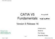
AP2257 - Draft A1 - Machined Part Modelling for CATIA V5
AP2257 - Draft A1 - Machined Part Modelling for CATIA V5
AP2257 - Draft A1 - Machined Part Modelling for CATIA V5

You also want an ePaper? Increase the reach of your titles
YUMPU automatically turns print PDFs into web optimized ePapers that Google loves.
AIRBUS<br />
Procedure<br />
<strong>AP2257</strong><br />
<strong>Machined</strong> <strong>Part</strong> <strong>Modelling</strong><br />
<strong>for</strong> <strong>CATIA</strong> <strong>V5</strong><br />
SCOPE:<br />
This document is relative to the modeling and know-how rules necessary with <strong>CATIA</strong><strong>V5</strong> to design a<br />
complex 5 axis machined part, including manufacturing needs.<br />
The guide contains different steps to define specific geometrical machining features as 2.5 axis, 4<br />
axis, and 5 axis pockets, as ribs.<br />
It describes :<br />
- Model organization and structure data<br />
- Rules to follow in case of design changes : How to show and model updated parts.<br />
Owner’s Approval:<br />
Authorization:<br />
Date :<br />
Name<br />
Function<br />
: Bruno Maître EMK-T<br />
: Head of <strong>CATIA</strong> <strong>V5</strong> methods <strong>for</strong> French<br />
Team<br />
Name<br />
Function<br />
: Ulrich SCHUMANN-HINDENBERG<br />
: Head of CAD-CAM CM (EMK)<br />
© Airbus 2002 . All rights reserved. This document contains Airbus proprietary in<strong>for</strong>mation and trade secrets. It shall at all times<br />
remain the property of Airbus; no intellectual property right or licence is granted by Airbus in connection with any in<strong>for</strong>mation<br />
contained in it. It is supplied on the express condition that said in<strong>for</strong>mation is treated as confidential, shall not be used <strong>for</strong> any<br />
purpose other than that <strong>for</strong> which it is supplied, shall not be disclosed in whole or in part, to third parties other than the Airbus<br />
Members and Associated <strong>Part</strong>ners, their subcontractors and suppliers (to the extent of their involvement in Airbus projects),<br />
without Airbus prior written consent.<br />
Issue: <strong>Draft</strong> <strong>A1</strong> Date: 13 February 2002 Page 1 of 46
AIRBUS<br />
<strong>Machined</strong> <strong>Part</strong> <strong>Modelling</strong> <strong>for</strong> <strong>CATIA</strong> <strong>V5</strong><br />
<strong>AP2257</strong><br />
Table of contents<br />
1 Introduction ............................................................................... 3<br />
2 General recommendations....................................................... 4<br />
2.1 Applicable rules ......................................................................................... 4<br />
2.2 Practical advice.......................................................................................... 5<br />
3 General modelling process...................................................... 6<br />
4 Detailed modelling process per type of difficulty ................ 20<br />
4.1 4 or 5 axis pocket with closed angle...................................................... 20<br />
4.1.1 Producing 2.5 axis pocket................................................................................ 20<br />
4.1.2 Solid definition of 5 axis pocket ...................................................................... 24<br />
4.2 4 or 5 axis pocket with open angle ........................................................ 29<br />
4.2.1 Producing 2.5 axis pocket................................................................................ 29<br />
4.2.2 Producing sloped pocket (4 - 5 axes).............................................................. 34<br />
4.3 Top of stiffener modelling....................................................................... 38<br />
4.4 Boss modelling ........................................................................................ 40<br />
5 Identifying modifications........................................................ 44<br />
5.1 Differences between solids made by layer ........................................... 44<br />
5.2 Difference between solids made by 3D modelling comparison.......... 45<br />
Reference documents ........................................................................................... 46<br />
Group of redaction ................................................................................................ 46<br />
Approval ................................................................................................................. 46<br />
Record of revisions ............................................................................................... 46<br />
Issue:<strong>Draft</strong> <strong>A1</strong> Date: 13 February 2002 Page 2 of 46
AIRBUS<br />
<strong>Machined</strong> <strong>Part</strong> <strong>Modelling</strong> <strong>for</strong> <strong>CATIA</strong> <strong>V5</strong><br />
<strong>AP2257</strong><br />
1 Introduction<br />
The aim being to:<br />
- Obtain exact geometry of the detail part,<br />
- Check and validate assemblies,<br />
- Facilitate modifications to geometry (design and production),<br />
- Avoid recreating additional geometry during the Numerical Control programming<br />
phases (the programmer will as far as possible use the solid defined by the Design<br />
Office as a basis).<br />
The method deals with general cases.<br />
Specific cases will be dealt with during CDBT meetings.<br />
For all definition principles relevant to:<br />
- Mean/nominal dimensions,<br />
- Major Definition Characteristics,<br />
- Drawing set integration (furnishing).<br />
! Consult AP2255, 3D modelling rules <strong>for</strong> <strong>CATIA</strong> <strong>V5</strong>.<br />
! Consult AP2260, Drawing rules <strong>for</strong> <strong>CATIA</strong> <strong>V5</strong>.<br />
Issue:<strong>Draft</strong> <strong>A1</strong> Date: 13 February 2002 Page 3 of 46
AIRBUS<br />
<strong>Machined</strong> <strong>Part</strong> <strong>Modelling</strong> <strong>for</strong> <strong>CATIA</strong> <strong>V5</strong><br />
<strong>AP2257</strong><br />
2 General recommendations<br />
2.1 Applicable rules<br />
- <strong>Modelling</strong> is done in <strong>CATIA</strong><strong>V5</strong> exact solid <strong>for</strong>m (<strong>Part</strong>Design Workshop). The<br />
resulting model is a CAT<strong>Part</strong>.<br />
Reminders: The intermediary geometry is created by means of sketches and elements<br />
obtained from the WireFrame & Surface Design workshop. The main contours bear on<br />
defined functional references such as the 3 main planes of the part (XY, ZX & YZ<br />
planes).<br />
- For parts taken from blanks, modelling must include the draft angles <strong>for</strong> the sections<br />
of the part not machined (by rework of supplier's contractual drawing).<br />
- The bores are modelled.<br />
- The threads and tapings are modelled by standard "holes" features:<br />
• to nominal diameter value <strong>for</strong> a thread,<br />
• to drilling diameter value <strong>for</strong> a tapping.<br />
- Definition of spot facings: Use the "hole" "counterbored" feature<br />
- Positioning reference system<br />
The part is modelled in its absolute axis system inside the CAT<strong>Part</strong> modelled by the 3<br />
main planes (XY, ZX, YZ).<br />
- The curves and surfaces from the SRG (Shape reference group) are defined in the<br />
CAD model. These elements have a property giving the reference of the basic GRF<br />
file. Be<strong>for</strong>e any construction work, the validity of the curve or the surface from the<br />
SRG must be checked. If the size of the surface is insufficient, a new reference<br />
must be requested from the SRG.<br />
- Abundantly use names and explicit comments during <strong>CATIA</strong> entity creation (right<br />
click on preselected entity + properties + feature properties).<br />
- For the definition of a feature, per<strong>for</strong>m the Boolean operations at latest possible<br />
stage in the history in order to be able to change more easily, during a modification,<br />
the topology of the latter. On completion of construction, there must be only one<br />
<strong>Part</strong>Body. Integration of restrictions is not dealt with here.<br />
- The construction elements will be located, if possible, on the drawing reference<br />
planes. Whenever possible, they must belong to sketches positioned on these<br />
planes. These elements will be constructed as and when the designer needs them.<br />
- Pockets will be modelled by the "pockets" features even <strong>for</strong> non-canonical shapes<br />
and this with the aim of optimising recognition of native features proposed by <strong>CATIA</strong><br />
<strong>V5</strong> in the machining workshop.<br />
- In a "Multi-body" approach, always prefer modelling of 2 bodies <strong>for</strong> a pocket; one<br />
body containing the definition of the pocket without fillets "assembled" with a body<br />
containing the fillet radii. This with the aim of more easily integrating the pocket<br />
bottom restrictions.<br />
Issue:<strong>Draft</strong> <strong>A1</strong> Date: 13 February 2002 Page 4 of 46
AIRBUS<br />
<strong>Machined</strong> <strong>Part</strong> <strong>Modelling</strong> <strong>for</strong> <strong>CATIA</strong> <strong>V5</strong><br />
<strong>AP2257</strong><br />
- Parameterising will be done by constraints on a sketch. Caution: all elements used<br />
in the current sketch must be defined in this current sketch or on a coplanar sketch<br />
plane. They must not be taken from surface elements external to the latter.<br />
- Do not create auxiliary co-ordinate systems (Reference axis) used <strong>for</strong> the<br />
positioning of the elements required <strong>for</strong> the construction of the part.<br />
2.2 Practical advice<br />
- When you modify an object (adding a fillet radius to a body), do not <strong>for</strong>get to<br />
activate the "Define in work object" command (Mouse Key 3).<br />
- When you want to delete an entity, take care not to destroy the parents but only the<br />
element in question. Deleting the parents is to be prohibited when the work of the<br />
definition phase is well under way.<br />
- The fillet radii of the walls of a pocket must not be defined on the sketch but as<br />
"fillet" features.<br />
Issue:<strong>Draft</strong> <strong>A1</strong> Date: 13 February 2002 Page 5 of 46
AIRBUS<br />
<strong>Machined</strong> <strong>Part</strong> <strong>Modelling</strong> <strong>for</strong> <strong>CATIA</strong> <strong>V5</strong><br />
<strong>AP2257</strong><br />
3 General modelling process<br />
The modelling method of the part illustrated below includes various machining<br />
particularities.<br />
- 2.5 axis pocket<br />
- 4 or 5 axis pocket with closed angle<br />
- 4 or 5 axis pocket with open angle<br />
- Increase in stiffener height<br />
Prismatic Pocket 0.3<br />
Prismatic Pocket 0.2<br />
2.5 & 5 axis<br />
Pocket 2<br />
Prismatic Pocket 0.1<br />
2.5 & 5 axis<br />
Pocket 4<br />
2.5 & 5 axis<br />
Pockets 1<br />
Boss<br />
Stiffener 1-2<br />
Prismatic<br />
Large Pocket<br />
Central Stiffener<br />
Stiffener 3-4<br />
2.5 & 5 axis<br />
Pocket 3<br />
Final solid including Design<br />
Feature identification<br />
Open Prismatic<br />
Pocket<br />
Step 1:<br />
Recovery of data on which part design will bear.<br />
Consists in grouping all of the resources used <strong>for</strong> the definition of the part and the <strong>Part</strong>,<br />
which will contain the definition of the part itself.<br />
Pipe element<br />
Outside surfaces<br />
Design Resources<br />
Issue:<strong>Draft</strong> <strong>A1</strong> Date: 13 February 2002 Page 6 of 46
AIRBUS<br />
<strong>Machined</strong> <strong>Part</strong> <strong>Modelling</strong> <strong>for</strong> <strong>CATIA</strong> <strong>V5</strong><br />
<strong>AP2257</strong><br />
Step 2:<br />
Creation of the outside contour of the part directly on a sketch positioned on one of the<br />
main planes of the <strong>Part</strong>.<br />
External resources<br />
required <strong>for</strong> the<br />
definition of the<br />
part.<br />
Here, visualisation<br />
of the surfaces is<br />
used only to<br />
correctly position<br />
the contour<br />
Definition of external<br />
contour<br />
Issue:<strong>Draft</strong> <strong>A1</strong> Date: 13 February 2002 Page 7 of 46
AIRBUS<br />
<strong>Machined</strong> <strong>Part</strong> <strong>Modelling</strong> <strong>for</strong> <strong>CATIA</strong> <strong>V5</strong><br />
<strong>AP2257</strong><br />
Step 3:<br />
Generation of the main solid (pad feature) from the contour.<br />
The fillet radii are created after generation of the prism. Group fillets with same<br />
definition by multi-selection. Prefer edge selection mode.<br />
First definition of main<br />
In case of non-evolution profile (constant section) <strong>for</strong> pad definition, define directly the<br />
solid by surface limitation.<br />
Surface1 used <strong>for</strong><br />
limitation<br />
Sketch<br />
Definition<br />
Surface2 used <strong>for</strong><br />
limitation<br />
Main Solid Definition by Surfaces<br />
Issue:<strong>Draft</strong> <strong>A1</strong> Date: 13 February 2002 Page 8 of 46
AIRBUS<br />
<strong>Machined</strong> <strong>Part</strong> <strong>Modelling</strong> <strong>for</strong> <strong>CATIA</strong> <strong>V5</strong><br />
<strong>AP2257</strong><br />
Step 4: Sculpture (split function,<br />
CAT<strong>Part</strong>.<br />
) the solid by the two surfaces referenced in the<br />
Splitting of part body by external surfaces<br />
Step 5: Creation of 2.5 axis pockets in "Multi-Body" approach<br />
- Creation of the contours of the 2.5 axis pocket.<br />
• Create in separate sketches but position on the reference planes the 3 sketches<br />
of the 3 pockets<br />
- Creation with 3 separate pocket features, , 3 elementary pockets<br />
<strong>Part</strong>Body<br />
Body containing the<br />
2.5 axis pockets<br />
Pockets 0.x Definition<br />
Issue:<strong>Draft</strong> <strong>A1</strong> Date: 13 February 2002 Page 9 of 46
AIRBUS<br />
<strong>Machined</strong> <strong>Part</strong> <strong>Modelling</strong> <strong>for</strong> <strong>CATIA</strong> <strong>V5</strong><br />
<strong>AP2257</strong><br />
The 3 elementary pockets have been assembled to comprise a body in its own right.<br />
The multi-body approach consists in separating the fillet radius entities from the bodies<br />
on which they bear. The aim of this is to facilitate later integration of the pocket bottom<br />
restrictions.<br />
General methodology <strong>for</strong> defining a pocket in multi-body approach:<br />
a- Insert a body (body1)<br />
b- Define the pocket without its radii (the body contains the sketch of the contour of the<br />
pocket and the resulting pocket feature)<br />
c- Insert a new body (body2)<br />
d- Assemble body1 and body2<br />
e- Activate body2<br />
f- Define the fillet radii in body2<br />
A body including fillets<br />
A body containing the "raw" contour<br />
« Multi-Body » Specification tree example<br />
Issue:<strong>Draft</strong> <strong>A1</strong> Date: 13 February 2002 Page 10 of 46
AIRBUS<br />
<strong>Machined</strong> <strong>Part</strong> <strong>Modelling</strong> <strong>for</strong> <strong>CATIA</strong> <strong>V5</strong><br />
<strong>AP2257</strong><br />
Step 6:<br />
Subtract the upper section<br />
- Creation of an additional body. Go to main plane YZ to define sketches.<br />
- Subtraction of the <strong>Part</strong>Body<br />
Issue:<strong>Draft</strong> <strong>A1</strong> Date: 13 February 2002 Page 11 of 46
AIRBUS<br />
<strong>Machined</strong> <strong>Part</strong> <strong>Modelling</strong> <strong>for</strong> <strong>CATIA</strong> <strong>V5</strong><br />
<strong>AP2257</strong><br />
Step 7:<br />
- 2.5 Axis Pockets 1, 2, 3 & 4 creation:<br />
• Create common sketches <strong>for</strong> 2.5 axis pocket 1&2 and <strong>for</strong> 2.5 axis pocket 3&4<br />
(identical transversal section) (see paragraph 4.1.1 & 4.2.1)<br />
• Create a new body <strong>for</strong> each pocket<br />
• Define a pocket <strong>for</strong> each one<br />
Pocket 4<br />
Pocket 2<br />
Pocket 3<br />
Pocket 1<br />
Set of 2.5 axis Pockets<br />
without fillets<br />
- Include the different fillet with a “multi-body” modelling<br />
• First, create the corner ones and secondly create the bottom pocket ones<br />
- Assembly them with <strong>Part</strong>Body<br />
2.5 Axis Pockets Assembled to the <strong>Part</strong> Body<br />
Issue:<strong>Draft</strong> <strong>A1</strong> Date: 13 February 2002 Page 12 of 46
AIRBUS<br />
<strong>Machined</strong> <strong>Part</strong> <strong>Modelling</strong> <strong>for</strong> <strong>CATIA</strong> <strong>V5</strong><br />
<strong>AP2257</strong><br />
Step 8:<br />
5 Axis Pockets 1, 2, 3 & 4 creation:<br />
- Create one body <strong>for</strong> each 5 axis pocket<br />
- Create one sketch <strong>for</strong> each 5 axis pocket<br />
• Create the cutting tool contour inside the different sketch (see paragraph 4.1.2 &<br />
4.2.2)<br />
- Create the different solid resulting from the cutting tool trajectory with slot features<br />
5 Axis Pocket 2<br />
5 Axis Pocket Solid<br />
- Assembly the different bodies with <strong>Part</strong> Body<br />
5 Axis Pocket 4<br />
5 Axis Pocket 1<br />
5 Axis Pocket 3<br />
5 Axis Pocket 2<br />
5 Axis Pockets Assembled<br />
Issue:<strong>Draft</strong> <strong>A1</strong> Date: 13 February 2002 Page 13 of 46
AIRBUS<br />
<strong>Machined</strong> <strong>Part</strong> <strong>Modelling</strong> <strong>for</strong> <strong>CATIA</strong> <strong>V5</strong><br />
<strong>AP2257</strong><br />
Step 9:<br />
Top of Stiffeners modelling (Stiffener 1-2, Stiffener 3-4 & Central Stiffener) (see<br />
paragraph 4.3)<br />
- Creation of separate bodies, one <strong>for</strong> the stiffener 1-2, one <strong>for</strong> the stiffener 3-4 and<br />
one <strong>for</strong> the central stiffener<br />
- Create the sketches defining the material to remove on stiffener top<br />
- Create the removed solid with the loft feature<br />
Top of Stiffener 3-4 Solid<br />
- Assembly the 3 bodies with <strong>Part</strong>Body<br />
Stiffeners Result on <strong>Part</strong> Body<br />
Issue:<strong>Draft</strong> <strong>A1</strong> Date: 13 February 2002 Page 14 of 46
AIRBUS<br />
<strong>Machined</strong> <strong>Part</strong> <strong>Modelling</strong> <strong>for</strong> <strong>CATIA</strong> <strong>V5</strong><br />
<strong>AP2257</strong><br />
Step 10:<br />
- Open Pocket <strong>Modelling</strong><br />
• Create a specific body<br />
• Define the pocket contour sketch (using solid edges to construct it)<br />
• Define the pocket feature<br />
Open Pocket Solid<br />
- Assembly with <strong>Part</strong>Body<br />
Open Pocket Result<br />
Issue:<strong>Draft</strong> <strong>A1</strong> Date: 13 February 2002 Page 15 of 46
AIRBUS<br />
<strong>Machined</strong> <strong>Part</strong> <strong>Modelling</strong> <strong>for</strong> <strong>CATIA</strong> <strong>V5</strong><br />
<strong>AP2257</strong><br />
Step 11:<br />
Adding the boss (see paragraph 4.4)<br />
Pipe resource use<br />
Boss in context<br />
modelling<br />
Boss<br />
Issue:<strong>Draft</strong> <strong>A1</strong> Date: 13 February 2002 Page 16 of 46
AIRBUS<br />
<strong>Machined</strong> <strong>Part</strong> <strong>Modelling</strong> <strong>for</strong> <strong>CATIA</strong> <strong>V5</strong><br />
<strong>AP2257</strong><br />
Step 12:<br />
Adding the 2.5 axis large pocket.<br />
- Creation of a separate body<br />
- Pocket sketch creation using 3D definition<br />
Sketch Plan :<br />
Z=4mm<br />
Coincidence<br />
constraint<br />
between a 3D<br />
edge and a sketch<br />
line<br />
Sketch of Large Pocket<br />
Issue:<strong>Draft</strong> <strong>A1</strong> Date: 13 February 2002 Page 17 of 46
AIRBUS<br />
<strong>Machined</strong> <strong>Part</strong> <strong>Modelling</strong> <strong>for</strong> <strong>CATIA</strong> <strong>V5</strong><br />
<strong>AP2257</strong><br />
- Pocket feature creation<br />
Feature Pocket<br />
Issue:<strong>Draft</strong> <strong>A1</strong> Date: 13 February 2002 Page 18 of 46
AIRBUS<br />
<strong>Machined</strong> <strong>Part</strong> <strong>Modelling</strong> <strong>for</strong> <strong>CATIA</strong> <strong>V5</strong><br />
<strong>AP2257</strong><br />
- Fillet modelling based on the ‘Multi-body’ methodology<br />
- Assembly with <strong>Part</strong>Body<br />
Step 13:<br />
Final solid<br />
Adding the fillet defined on resulting surface or edge coming from boolean operation<br />
Issue:<strong>Draft</strong> <strong>A1</strong> Date: 13 February 2002 Page 19 of 46
AIRBUS<br />
<strong>Machined</strong> <strong>Part</strong> <strong>Modelling</strong> <strong>for</strong> <strong>CATIA</strong> <strong>V5</strong><br />
<strong>AP2257</strong><br />
4 Detailed modelling process per type of difficulty<br />
4.1 4 or 5 axis pocket with closed angle<br />
4.1.1 Producing 2.5 axis pocket<br />
" Creation of pocket limit defined by a surface (S)<br />
- Definition of the pocket profile. Make the<br />
following steps in a new open body<br />
• In the WireFrame Surface Design<br />
workbench, make the intersection , the curve<br />
(C), between the top of part & an offset surface<br />
(Ss) of the small integral stiffener thickness (see<br />
figure ‘Intersection solid & Ss). The aim is to<br />
obtain the trace of the top part let by the cutting<br />
tool. The machining is made on 2.5 axis mode<br />
along Z.<br />
Ss<br />
Intersection solid & (Ss)<br />
C<br />
• In a second step, project (C) on the<br />
reference plane (Z= 0 mm). We obtain (C1) (see<br />
figure ‘curve projection’).<br />
• The profile is defined; we can create an<br />
C<br />
extruded surface (S1) defined by the (C1)<br />
curve and the Z-axis.<br />
• Define an offset surface (S1off) from (S1).<br />
The distance between the 2 surfaces is equal to<br />
0.5 mm. This overthickness allow to let material to<br />
remove <strong>for</strong> the 5 axis machining (see paragraph<br />
4.1.2)<br />
#(S1off) will be used to limit the pocket.<br />
Curve Projection<br />
S1<br />
C1<br />
Offset Surface (Soff)<br />
distant of 0.5 mm from<br />
(Ss)<br />
Extrude Surface<br />
- Definition of the pocket contour<br />
Offset Surface<br />
Issue:<strong>Draft</strong> <strong>A1</strong> Date: 13 February 2002 Page 20 of 46
AIRBUS<br />
<strong>Machined</strong> <strong>Part</strong> <strong>Modelling</strong> <strong>for</strong> <strong>CATIA</strong> <strong>V5</strong><br />
<strong>AP2257</strong><br />
• In the <strong>Part</strong> Design workbench, insert a new body<br />
• Create the following in sketch in the Z=0 mm plan<br />
Pocket 1 & 2 section<br />
! The pocket 1 section is the same as the pocket 3 one. By consequence, we are going to<br />
use this sketch <strong>for</strong> the pocket 1 & the pocket 3 definition. In that way, a modification in<br />
this sketch will impact the 2 pockets<br />
Issue:<strong>Draft</strong> <strong>A1</strong> Date: 13 February 2002 Page 21 of 46
AIRBUS<br />
<strong>Machined</strong> <strong>Part</strong> <strong>Modelling</strong> <strong>for</strong> <strong>CATIA</strong> <strong>V5</strong><br />
<strong>AP2257</strong><br />
• Pocket Feature Definition<br />
• Create a pocket feature as follow<br />
Pocket 1 Feature creation<br />
Issue:<strong>Draft</strong> <strong>A1</strong> Date: 13 February 2002 Page 22 of 46
AIRBUS<br />
<strong>Machined</strong> <strong>Part</strong> <strong>Modelling</strong> <strong>for</strong> <strong>CATIA</strong> <strong>V5</strong><br />
<strong>AP2257</strong><br />
• Creation of fillet radii on the walls and bottoms of the pockets (multi-body<br />
approach: see Step 5)<br />
• Create the various fillet radii.<br />
R=11 mm<br />
R=20 mm<br />
R= 4 mm (bottom of<br />
pocket)<br />
2.5 axis pockets with fillets<br />
• Assemble the pocket with the <strong>Part</strong>Body.<br />
Issue:<strong>Draft</strong> <strong>A1</strong> Date: 13 February 2002 Page 23 of 46
AIRBUS<br />
<strong>Machined</strong> <strong>Part</strong> <strong>Modelling</strong> <strong>for</strong> <strong>CATIA</strong> <strong>V5</strong><br />
<strong>AP2257</strong><br />
4.1.2 Solid definition of 5 axis pocket<br />
- Insert a new body.<br />
- Define a plane (P) normal to the bottom of the pocket on the centre axis of the prismatic<br />
pocket.<br />
- Define the intersection of plane (P) with the surface (S) obtained from the outer skin of<br />
the part "offset" by the value of the small integral stiffener.<br />
- Define the intersection of the bottom of the pocket with (S).<br />
- Definition of sketch.<br />
Intersection of (P) with (S): (C)<br />
Intersection of pocket<br />
bottom plane with (S):<br />
(Cm)<br />
Sketch plane (P)<br />
Intersection curves<br />
Issue:<strong>Draft</strong> <strong>A1</strong> Date: 13 February 2002 Page 24 of 46
AIRBUS<br />
<strong>Machined</strong> <strong>Part</strong> <strong>Modelling</strong> <strong>for</strong> <strong>CATIA</strong> <strong>V5</strong><br />
<strong>AP2257</strong><br />
- Definition of 5 axis pocket contour without fillets (use of constraints on the sketch)<br />
• On the sketch plane (P), project the curve (C). We will bear on (Cproj) to construct<br />
the line of the tool on this plane.<br />
• Define a line parallel to the reference plane (XY) offset by the value of the thickness<br />
of the pocket bottom + offset of 0.3 mm (D).<br />
• Create a line (C1) parallel to (C) offset by the value of the diameter of the tool + 1<br />
mm.<br />
• Define a circle (Ci1), modelling the tool corner radius, tangent to (C1) and to (D).<br />
(Ci1)<br />
(C1)<br />
Tool corner radius R = 4<br />
mm<br />
(C1) 17 mm from (C)<br />
(Cproj)<br />
Line (D) parallel to<br />
reference plane offset by 5<br />
mm + 0.3 mm<br />
Definition of tool side (Ci1) on (P)<br />
Issue:<strong>Draft</strong> <strong>A1</strong> Date: 13 February 2002 Page 25 of 46
AIRBUS<br />
<strong>Machined</strong> <strong>Part</strong> <strong>Modelling</strong> <strong>for</strong> <strong>CATIA</strong> <strong>V5</strong><br />
<strong>AP2257</strong><br />
- Define a line (D1) modelling the bottom of the tool tangent to (Ci1) and perpendicular to<br />
(Cproj). For an unruled surface, construct the sweep line (Db) from (C1).<br />
(Ci1)<br />
(Cproj)<br />
(D1):<br />
- perpendicular to<br />
(Cproj)<br />
- tangent to (Ci1)<br />
Definition of (D1), line modelling the bottom of the tool<br />
Case of a surface with double curvature<br />
Issue:<strong>Draft</strong> <strong>A1</strong> Date: 13 February 2002 Page 26 of 46
AIRBUS<br />
<strong>Machined</strong> <strong>Part</strong> <strong>Modelling</strong> <strong>for</strong> <strong>CATIA</strong> <strong>V5</strong><br />
<strong>AP2257</strong><br />
Closing of contour<br />
(Ci1) and (D) must be defined as<br />
construction elements as they do<br />
not participate in the definition of<br />
the contour<br />
Definition of contour<br />
The fillet radii will be modelled outside the sketch.<br />
☞ Refer to AP2255 – 3D modelling rules <strong>for</strong> <strong>CATIA</strong> <strong>V5</strong>.<br />
- Creation of sloped closed pocket solid (4 or 5 axes)<br />
• From the contour (Cs) on the sketch and the curve (Cm), define a "slot" feature<br />
with:<br />
As guide curve: (Cm)<br />
As profile: (Cs)<br />
Guide curve : Cm<br />
Cutting tool profile : Cs<br />
Issue:<strong>Draft</strong> <strong>A1</strong> Date: 13 February 2002 Page 27 of 46
AIRBUS<br />
<strong>Machined</strong> <strong>Part</strong> <strong>Modelling</strong> <strong>for</strong> <strong>CATIA</strong> <strong>V5</strong><br />
<strong>AP2257</strong><br />
- Relimit the solid including the 0.3 mm offset on the walls (to avoid the tool was in<br />
contact with the.5 axis wall previously machined<br />
• Create the solid relimited by 2 splits.<br />
using <strong>Part</strong>Body surfaces<br />
5 axis pocket<br />
Split<br />
Surfaces<br />
Relimiting the solid<br />
! Use the "split" function rather than adding a "thickness" operator. Indeed, the<br />
"thickness" operator models a prism from the selected surface. Discontinuities may<br />
appear <strong>for</strong> solids when the curvature of the guide curve is high.<br />
- Add an over thickness of 0.3 mm to avoid cutting tool contact<br />
• Use an overthickness of 0.3 mm on 2 prismatic sections (as seen on image below)<br />
Surfaces on which<br />
overthickness is<br />
applied<br />
Overthickness<br />
Issue:<strong>Draft</strong> <strong>A1</strong> Date: 13 February 2002 Page 28 of 46
AIRBUS<br />
<strong>Machined</strong> <strong>Part</strong> <strong>Modelling</strong> <strong>for</strong> <strong>CATIA</strong> <strong>V5</strong><br />
<strong>AP2257</strong><br />
- Insertion of fillet radii in multi-body approach<br />
• To the body in progress, add fillet radii:<br />
1- For the walls (8.5 mm radius).<br />
2- For the pocket bottoms (4 mm radius).<br />
- Assemble this new pocket with the <strong>Part</strong>Body<br />
4.2 4 or 5 axis pocket with open angle<br />
4.2.1 Producing 2.5 axis pocket<br />
- Definition of section construction plane<br />
! For correct distribution of the data, create a new "OpenBody" with a specific name in<br />
which we will find all of the construction data used <strong>for</strong> the construction of the 2.5 axis and<br />
5 axis pockets. Indeed, these elements do not directly participate in the definition of the<br />
pocket contours. They must there<strong>for</strong>e not appear in the sketch associated with the "body"<br />
defining the latter.<br />
• Construct the "offset" surface (S1) from the outer surface of the part offset by<br />
the value of the small integral stiffener thickness.<br />
• Define the pocket thickness plane intersection curve (C2) with the small integral<br />
stiffener inner surface (S1).<br />
• Construct a plane (P1) normal to the inner line of the contour passing through its<br />
centre. Use here the plane (P) previously used to define the 5 axis pocket.<br />
• Define the intersection curve between (P1) and (S1) called (C3).<br />
• Construct on plane (P1) the sketch containing the construction elements used to<br />
determine the contour of the 2.5 axis pocket.<br />
Issue:<strong>Draft</strong> <strong>A1</strong> Date: 13 February 2002 Page 29 of 46
AIRBUS<br />
<strong>Machined</strong> <strong>Part</strong> <strong>Modelling</strong> <strong>for</strong> <strong>CATIA</strong> <strong>V5</strong><br />
<strong>AP2257</strong><br />
Line of pocket in<br />
this section to be<br />
determined<br />
(4)<br />
L1 = Inner profile line<br />
Profile line (C3),<br />
L2<br />
L4<br />
L3<br />
0.3<br />
R1<br />
0.3<br />
4.5 (Pocket thickness)<br />
SECTION through (P1)<br />
- Necessary resources to compute the profile (C3) & (L3) (see picture above :<br />
‘SECTION through (P1)<br />
" Indeed, we need to know the (C3) profile and (L3) lines defined in the sketch plan (P1) used to<br />
construct the tool profile<br />
! Use the same sketch plan (P1) as used to define the 5 axis pocket 1<br />
• In a new open body, define the intersection between the (P1) and an offset<br />
surface (Ss1) of the small integral stiffener thickness (see picture below)<br />
• In the same open body, define the intersection between (Ss1) and the plan<br />
Z=4.5mm corresponding to the pocket thickness.(see picture below)<br />
Issue:<strong>Draft</strong> <strong>A1</strong> Date: 13 February 2002 Page 30 of 46
AIRBUS<br />
<strong>Machined</strong> <strong>Part</strong> <strong>Modelling</strong> <strong>for</strong> <strong>CATIA</strong> <strong>V5</strong><br />
<strong>AP2257</strong><br />
(C3)<br />
Sketch plan<br />
(P1)<br />
(L4)<br />
Resources<br />
- Dp, the tool profile, construction (see figure ‘Resulting sketch’):<br />
! All the geometry at this step is defined in construction mode<br />
• Create a sketch (Sk1) with (P1) as support.<br />
• L5 coincident with (C3).<br />
• 0.3 mm offset to obtain L2.<br />
• L31 coincident with L3.<br />
• Construction of circle with radius R1. 3 constraints are associated: tangent to<br />
L21, L31 and radius of 4 mm.<br />
• Construction of Dp from the 2 constraints, a direction, here, vertical and tangent<br />
to the circle of radius R1.<br />
- Offset computation to create the pocket limit surface<br />
" Compute the offset between (Dp) and L5 (equal to C3) on the pocket plane Z=4.5 mm<br />
• Trim the different element to obtain the 2 points (Po1) and (Po2)<br />
• Compute the messier between these 2 elements<br />
# We find 0.62mm as offset distance<br />
Issue:<strong>Draft</strong> <strong>A1</strong> Date: 13 February 2002 Page 31 of 46
AIRBUS<br />
<strong>Machined</strong> <strong>Part</strong> <strong>Modelling</strong> <strong>for</strong> <strong>CATIA</strong> <strong>V5</strong><br />
<strong>AP2257</strong><br />
L2 parallel to<br />
L5<br />
L5 coincident<br />
with (C3)<br />
Tool corner diameter,<br />
D=8mm<br />
P01<br />
P02<br />
Line, Dp, of pocket<br />
profile<br />
L31<br />
coincident<br />
with (L3)<br />
(C3)in the sketch<br />
plane<br />
Overthickness of<br />
0.3 mm<br />
Resulting sketch &<br />
offset analyse<br />
Issue:<strong>Draft</strong> <strong>A1</strong> Date: 13 February 2002 Page 32 of 46
AIRBUS<br />
<strong>Machined</strong> <strong>Part</strong> <strong>Modelling</strong> <strong>for</strong> <strong>CATIA</strong> <strong>V5</strong><br />
<strong>AP2257</strong><br />
- Definition of pocket limit surface<br />
" Once you know the offset value, we can construct in the same open body, the corresponding<br />
offset curve in the WireFrame workbench<br />
• Define the offset surface (Ss1’) from (Ss1) distant from the offset value (here,<br />
0.62 mm)<br />
• Compute the intersection between (Ss1’) and the pocket plane Z=4.5 mm<br />
• Construct the extrude surface (Sl) defined by this intersection & Z axis (Z<br />
corresponding to the machining axis)<br />
- Creation of pocket feature without fillets<br />
• Create a new body<br />
• Use the same sketch as <strong>for</strong> the previous 2.5 axis pocket (see paragraph 4.1.1)<br />
• Define the pocket feature with the extrude surface as one limit and the<br />
plan y=2mm as the other<br />
(Sl)<br />
Y=2mm<br />
limit<br />
Prismatic Pocket 2 feature<br />
- Constructing fillet radii<br />
• In a multi-body approach, add the fillet radii to the walls (R = 11 mm) then to the<br />
bottom (R = 4 mm)<br />
Issue:<strong>Draft</strong> <strong>A1</strong> Date: 13 February 2002 Page 33 of 46
AIRBUS<br />
<strong>Machined</strong> <strong>Part</strong> <strong>Modelling</strong> <strong>for</strong> <strong>CATIA</strong> <strong>V5</strong><br />
<strong>AP2257</strong><br />
2.5 axis pocket including fillets<br />
(multi-body approach)<br />
4.2.2 Producing sloped pocket (4 - 5 axes)<br />
Definition: Production of fillet radius R2 between inner profile L1 and 0.3 mm offset in<br />
relation to bottom of pocket L4.<br />
L1 = Inner profile line<br />
R2<br />
Pocket bottom<br />
plane<br />
0.3<br />
L4<br />
Issue:<strong>Draft</strong> <strong>A1</strong> Date: 13 February 2002 Page 34 of 46
AIRBUS<br />
<strong>Machined</strong> <strong>Part</strong> <strong>Modelling</strong> <strong>for</strong> <strong>CATIA</strong> <strong>V5</strong><br />
<strong>AP2257</strong><br />
- Positioning of fillet radius<br />
• Edit the previous sketch (Sk1).<br />
• Add the following in<strong>for</strong>mation :<br />
Circle modelling R2 tangent<br />
to (L1) & (L4)<br />
L1<br />
0.3 mm from bottom<br />
of pocket<br />
L4<br />
Line created previously modelling the<br />
bottom of the pocket<br />
Sketch <strong>for</strong> modelling R2<br />
Issue:<strong>Draft</strong> <strong>A1</strong> Date: 13 February 2002 Page 35 of 46
AIRBUS<br />
<strong>Machined</strong> <strong>Part</strong> <strong>Modelling</strong> <strong>for</strong> <strong>CATIA</strong> <strong>V5</strong><br />
<strong>AP2257</strong><br />
- Determining tool "section"<br />
• Construction of elements (L6) & (L7) to model the cutting tool.<br />
Φ + 1<br />
L7 = Other side of<br />
the tool<br />
L1 = Inner profile line<br />
Elements to be<br />
constructed<br />
R2<br />
L6 = Line normal to L1<br />
(bottom of tool)<br />
- Define the cutting tool contour in the same sketch (Sk1)<br />
$ Excepted the cutting tool contour, all the geometric elements belonging to this sketch<br />
have to be defined as construction ones.<br />
Issue:<strong>Draft</strong> <strong>A1</strong> Date: 13 February 2002 Page 36 of 46
AIRBUS<br />
<strong>Machined</strong> <strong>Part</strong> <strong>Modelling</strong> <strong>for</strong> <strong>CATIA</strong> <strong>V5</strong><br />
<strong>AP2257</strong><br />
L1 = Inner profile line<br />
L6<br />
α<br />
Z plane<br />
P1<br />
Remark:<br />
In cases where angle α of surface has a high variation, construct two<br />
sections at the limits of the pocket to be processed and take plane Z<br />
passing via the highest point.<br />
This is valid <strong>for</strong> an open or a closed angle.<br />
- Creation of sloped closed pocket solid without fillets<br />
• Use the same methodology as in the paragraph 4.1.2, in the ‘Creation of sloped<br />
closed pocket solid’ scenario<br />
Use to define the slot feature (Cm) (see paragraph 4.1.2) as guide curve and<br />
the sketch (Sk1) as profile<br />
- Fillet creation with a ‘multi-body’ methodology<br />
Issue:<strong>Draft</strong> <strong>A1</strong> Date: 13 February 2002 Page 37 of 46
AIRBUS<br />
<strong>Machined</strong> <strong>Part</strong> <strong>Modelling</strong> <strong>for</strong> <strong>CATIA</strong> <strong>V5</strong><br />
<strong>AP2257</strong><br />
4.3 Top of stiffener modelling<br />
Definition: Create removed material on top of stiffener<br />
We will use loft functionality allowing creating rapidly non-constant profile between<br />
several sections.<br />
- Creation of sketch sections<br />
• In the WireFrame & Surface workbench, inside a new open body, create 2<br />
planes corresponding to the loft feature thickness<br />
• Insert a new body<br />
• In one of the 2 planes, create a sketch defining the loft section<br />
Sketch section<br />
• Duplicate this sketch in a new one (In this case, the profile is constant)<br />
• Change the sketch support and select the second plane<br />
Issue:<strong>Draft</strong> <strong>A1</strong> Date: 13 February 2002 Page 38 of 46
AIRBUS<br />
<strong>Machined</strong> <strong>Part</strong> <strong>Modelling</strong> <strong>for</strong> <strong>CATIA</strong> <strong>V5</strong><br />
<strong>AP2257</strong><br />
- Loft feature creation<br />
• In the same body, define the loft feature using the 2 sketch<br />
Section 1<br />
Section 2<br />
Sections Definition<br />
- Loft feature assembly with part body<br />
Result on part<br />
Issue:<strong>Draft</strong> <strong>A1</strong> Date: 13 February 2002 Page 39 of 46
AIRBUS<br />
<strong>Machined</strong> <strong>Part</strong> <strong>Modelling</strong> <strong>for</strong> <strong>CATIA</strong> <strong>V5</strong><br />
<strong>AP2257</strong><br />
4.4 Boss modelling<br />
Definition: Create a boss on the bottom of pocket.<br />
We will use a material "addition" methodology to construct a boss on a previously<br />
defined pocket.<br />
We will remove material by modelling the centre hole.<br />
The aim is to bear using existing resource, the tube, to create and correctly position this<br />
boss.<br />
Set the element of the pipe<br />
used to Show mode<br />
Definition of boss in context<br />
- Creation of boss without hole<br />
• Create the intersection curve between the tube and the bottom of the pocket.<br />
- Creation of geometry without "fillets".<br />
• Insert a new body<br />
• Creation of a pad feature in the <strong>Part</strong>Body.<br />
• Select the bottom of the pocket as sketch plane.<br />
• Create the circular contour of the boss: Position the boss by a concentricity<br />
constraint with the intersection curve to dimension the thickness of the boss.<br />
Issue:<strong>Draft</strong> <strong>A1</strong> Date: 13 February 2002 Page 40 of 46
AIRBUS<br />
<strong>Machined</strong> <strong>Part</strong> <strong>Modelling</strong> <strong>for</strong> <strong>CATIA</strong> <strong>V5</strong><br />
<strong>AP2257</strong><br />
After having positioned<br />
one in relation to the<br />
other, you can define a<br />
distance constraint<br />
Intersection curve<br />
between the bottom of<br />
the pocket and the<br />
element<br />
The 2 contours are<br />
positioned relatively via<br />
a concentricity<br />
constraint<br />
Positioning of boss contour<br />
Boss contour<br />
• Once the contour has been correctly positioned, create a 3.2 mm thick "pad".<br />
- Creation of the hole or a pocket associated with the boss<br />
! Create a hole or pocket feature according to the size of the element. This definition is<br />
related to the machining process that used later, adapted to suit a pocket or a hole. On<br />
account of the dimensions, choose to define this feature as a pocket.<br />
• Define the contour of the hole taking position in relation to the previous sketch.<br />
Positioning of pocket contour<br />
Issue:<strong>Draft</strong> <strong>A1</strong> Date: 13 February 2002 Page 41 of 46
AIRBUS<br />
<strong>Machined</strong> <strong>Part</strong> <strong>Modelling</strong> <strong>for</strong> <strong>CATIA</strong> <strong>V5</strong><br />
<strong>AP2257</strong><br />
• Define a pocket feature<br />
Definition of circular pocket<br />
Issue:<strong>Draft</strong> <strong>A1</strong> Date: 13 February 2002 Page 42 of 46
AIRBUS<br />
<strong>Machined</strong> <strong>Part</strong> <strong>Modelling</strong> <strong>for</strong> <strong>CATIA</strong> <strong>V5</strong><br />
<strong>AP2257</strong><br />
- Creation of "fillets" (No ‘multi-body approach)<br />
• Assemble this new body with the <strong>Part</strong>Body.<br />
• Create the "fillet": See example below. For a radius greater than the height of the<br />
boss, select the "Edge(s) to keep" option after clicking on the “more” button.<br />
Edge to be<br />
conserved<br />
Definition of the "fillet"<br />
93 27 44<br />
Materialisation of the "fillet"<br />
Issue:<strong>Draft</strong> <strong>A1</strong> Date: 13 February 2002 Page 43 of 46
AIRBUS<br />
<strong>Machined</strong> <strong>Part</strong> <strong>Modelling</strong> <strong>for</strong> <strong>CATIA</strong> <strong>V5</strong><br />
<strong>AP2257</strong><br />
5 Identifying modifications<br />
5.1 Differences between solids made by layer<br />
New part<br />
The modification is identified on the new solid by an extraction at a specific layer of the<br />
main modified face or faces.<br />
All adjacent faces affected by the movement of the main face are not extracted to<br />
identify the modification.<br />
Extracted face (new<br />
face)<br />
Issue:<strong>Draft</strong> <strong>A1</strong> Date: 13 February 2002 Page 44 of 46
AIRBUS<br />
<strong>Machined</strong> <strong>Part</strong> <strong>Modelling</strong> <strong>for</strong> <strong>CATIA</strong> <strong>V5</strong><br />
<strong>AP2257</strong><br />
5.2 Difference between solids made by 3D modelling comparison<br />
Directly in the DMU Space Analysis, you can compare 2 solids (included in a temporally<br />
same CATProduct). The methodology supposes the previous version of solid is<br />
available.<br />
- Construct a product including the 2 versions of solid<br />
- Active the compare 2 products command included in the DMU Space analysis<br />
workbench<br />
- Select the previous and the new solid and select “Added + Removed” and “solid<br />
comparison.<br />
" <strong>CATIA</strong><strong>V5</strong> will create “3dmap” file, a CGR file, called 3Added material” and “Removed material”.<br />
- Include these files in the CATProduct<br />
! Change the graphic properties of these files. For example, choose red colour <strong>for</strong> removed<br />
material and green <strong>for</strong> added material<br />
Solid comparison<br />
Issue:<strong>Draft</strong> <strong>A1</strong> Date: 13 February 2002 Page 45 of 46
AIRBUS<br />
<strong>Machined</strong> <strong>Part</strong> <strong>Modelling</strong> <strong>for</strong> <strong>CATIA</strong> <strong>V5</strong><br />
<strong>AP2257</strong><br />
Reference documents<br />
AP 2622<br />
AP 2610<br />
AP 2260<br />
AP 2255<br />
ABD 0004<br />
CAD layers organisation<br />
Naming and Numbering <strong>for</strong> New Projects<br />
Drawing rules <strong>for</strong> <strong>CATIA</strong> <strong>V5</strong><br />
3D <strong>Modelling</strong> rules <strong>for</strong> <strong>CATIA</strong> <strong>V5</strong><br />
Definition dossier<br />
Group of redaction<br />
Team Members Company / Department Telephone<br />
CANO-RODRIGUEZ Pedro Airbus España +34 916241292<br />
Gilles MERCADIER EMK-T +33 561184933<br />
Approval<br />
This document has been approved on behalf of the following:<br />
(signatures or proof of agreement are archived together with the master document)<br />
Organization<br />
ACE/SPD/Elementary parts/<br />
Mechanical <strong>Part</strong>s Generic<br />
CoC Structure<br />
EM Quality Assurance<br />
representative<br />
Approval<br />
C .Vergez - OIMM1<br />
H Schnell - ESDS<br />
Nicole Lamothe - EMZQ<br />
Record of revisions<br />
Issue Date Summary and reasons <strong>for</strong> changes<br />
<strong>Draft</strong> <strong>A1</strong> February 2002 Initial issue<br />
If you have a query concerning the implementation or updating of this document, please<br />
contact the Owner on page 1<br />
Or a team member of the group of redaction<br />
For general queries or in<strong>for</strong>mation contact:<br />
Airbus Documentation Office,<br />
Airbus<br />
31707 Blagnac CEDEX,<br />
France<br />
Tel: 33 (0)5 61 93 49 93<br />
Fax: 33 (0)5 61 93 27 44<br />
Issue:<strong>Draft</strong> <strong>A1</strong> Date: 13 February 2002 Page 46 of 46