When forces are continuously distributed over a region of a structure ...
When forces are continuously distributed over a region of a structure ...
When forces are continuously distributed over a region of a structure ...

Create successful ePaper yourself
Turn your PDF publications into a flip-book with our unique Google optimized e-Paper software.
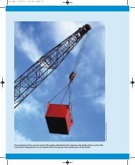
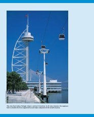
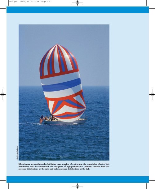
c05.qxd 10/29/07 1:17 PM Page 234© Corbis/Media Bakery<strong>When</strong> <strong>forces</strong> <strong>are</strong> <strong>continuously</strong> <strong>distributed</strong> <strong>over</strong> a <strong>region</strong> <strong>of</strong> a <strong>structure</strong>, the cumulative effect <strong>of</strong> thisdistribution must be determined. The designers <strong>of</strong> high-performance sailboats consider both airpressuredistributions on the sails and water-pressure distributions on the hull.
c05.qxd 10/29/07 1:17 PM Page 2355DISTRIBUTEDFORCESCHAPTER OUTLINE5/1 IntroductionSECTION A CENTERS OF MASS AND CENTROIDS5/2 Center <strong>of</strong> Mass5/3 Centroids <strong>of</strong> Lines, Areas, and Volumes5/4 Composite Bodies and Figures; Approximations5/5 Theorems <strong>of</strong> PappusSECTION B SPECIAL TOPICS5/6 Beams—External Effects5/7 Beams—Internal Effects5/8 Flexible Cables5/9 Fluid Statics5/10 Chapter Review5/1 INTRODUCTIONIn the previous chapters we treated all <strong>forces</strong> as concentrated alongtheir lines <strong>of</strong> action and at their points <strong>of</strong> application. This treatmentprovided a reasonable model for those <strong>forces</strong>. Actually, “concentrated”<strong>forces</strong> do not exist in the exact sense, since every external force appliedmechanically to a body is <strong>distributed</strong> <strong>over</strong> a finite contact <strong>are</strong>a, howeversmall.The force exerted by the pavement on an automobile tire, for instance,is applied to the tire <strong>over</strong> its entire <strong>are</strong>a <strong>of</strong> contact, Fig. 5/1a,which may be appreciable if the tire is s<strong>of</strong>t. <strong>When</strong> analyzing the <strong>forces</strong>acting on the car as a whole, if the dimension b <strong>of</strong> the contact <strong>are</strong>a isnegligible comp<strong>are</strong>d with the other pertinent dimensions, such as thedistance between wheels, then we may replace the actual <strong>distributed</strong>contact <strong>forces</strong> by their resultant R treated as a concentrated force. Eventhe force <strong>of</strong> contact between a hardened steel ball and its race in aloaded ball bearing, Fig. 5/1b, is applied <strong>over</strong> a finite though extremelysmall contact <strong>are</strong>a. The <strong>forces</strong> applied to a two-force member <strong>of</strong> a truss,Fig. 5/1c, <strong>are</strong> applied <strong>over</strong> an actual <strong>are</strong>a <strong>of</strong> contact <strong>of</strong> the pin againstthe hole and internally across the cut section as shown. In these andother similar examples we may treat the <strong>forces</strong> as concentrated whenanalyzing their external effects on bodies as a whole.235
c05.qxd 10/29/07 1:17 PM Page 236236 Chapter 5 Distributed Forcesb(a)REnlarged view<strong>of</strong> contactIf, on the other hand, we want to find the distribution <strong>of</strong> internal<strong>forces</strong> in the material <strong>of</strong> the body near the contact location, where theinternal stresses and strains may be appreciable, then we must nottreat the load as concentrated but must consider the actual distribution.This problem will not be discussed here because it requires a knowledge<strong>of</strong> the properties <strong>of</strong> the material and belongs in more advanced treatments<strong>of</strong> the mechanics <strong>of</strong> materials and the theories <strong>of</strong> elasticity andplasticity.<strong>When</strong> <strong>forces</strong> <strong>are</strong> applied <strong>over</strong> a <strong>region</strong> whose dimensions <strong>are</strong> notnegligible comp<strong>are</strong>d with other pertinent dimensions, then we must accountfor the actual manner in which the force is <strong>distributed</strong>. We dothis by summing the effects <strong>of</strong> the <strong>distributed</strong> force <strong>over</strong> the entire <strong>region</strong>using mathematical integration. This requires that we know theintensity <strong>of</strong> the force at any location. There <strong>are</strong> three categories <strong>of</strong> suchproblems.CRC(b)(b)RC(1) Line Distribution. <strong>When</strong> a force is <strong>distributed</strong> along a line, as inthe continuous vertical load supported by a suspended cable, Fig. 5/2a,the intensity w <strong>of</strong> the loading is expressed as force per unit length <strong>of</strong>line, newtons per meter (N/m) or pounds per foot (lb/ft).(2) Area Distribution. <strong>When</strong> a force is <strong>distributed</strong> <strong>over</strong> an <strong>are</strong>a, aswith the hydraulic pressure <strong>of</strong> water against the inner face <strong>of</strong> a section<strong>of</strong> dam, Fig. 5/2b, the intensity is expressed as force per unit <strong>are</strong>a. Thisintensity is called pressure for the action <strong>of</strong> fluid <strong>forces</strong> and stress for theinternal distribution <strong>of</strong> <strong>forces</strong> in solids. The basic unit for pressure orstress in SI is the newton per squ<strong>are</strong> meter (N/m 2 ), which is also calledthe pascal (Pa). This unit, however, is too small for most applications(6895 Pa 1 lb/in. 2 ). The kilopascal (kPa), which equals 10 3 Pa, is morecommonly used for fluid pressure, and the megapascal, which equals 10 6Pa, is used for stress. In the U.S. customary system <strong>of</strong> units, both fluidpressure and mechanical stress <strong>are</strong> commonly expressed in pounds persqu<strong>are</strong> inch (lb/in. 2 ).C(c)Figure 5/1(3) Volume Distribution. A force which is <strong>distributed</strong> <strong>over</strong> the volume<strong>of</strong> a body is called a body force. The most common body force is theforce <strong>of</strong> gravitational attraction, which acts on all elements <strong>of</strong> mass in abody. The determination <strong>of</strong> the <strong>forces</strong> on the supports <strong>of</strong> the heavy cantilevered<strong>structure</strong> in Fig. 5/2c, for example, would require accountingfor the distribution <strong>of</strong> gravitational force throughout the <strong>structure</strong>. Theintensity <strong>of</strong> gravitational force is the specific weight g, where is thedensity (mass per unit volume) and g is the acceleration due to gravity.The units for g <strong>are</strong> (kg/m 3 )(m/s 2 ) N/m 3 in SI units and lb/ft 3 or lb/in. 3in the U.S. customary system.The body force due to the gravitational attraction <strong>of</strong> the earth(weight) is by far the most commonly encountered <strong>distributed</strong> force.Section A <strong>of</strong> this chapter treats the determination <strong>of</strong> the point in a bodythrough which the resultant gravitational force acts, and discusses theassociated geometric properties <strong>of</strong> lines, <strong>are</strong>as, and volumes. Section Btreats <strong>distributed</strong> <strong>forces</strong> which act on and in beams and flexible cablesand <strong>distributed</strong> <strong>forces</strong> which fluids exert on exposed surfaces.
c05.qxd 10/29/07 1:17 PM Page 237Article 5/2 Center <strong>of</strong> Mass 237w(a)(b)Figure 5/2(c)SECTION ACENTERS OF MASS AND CENTROIDS5/2 CENTER OF M ASSConsider a three-dimensional body <strong>of</strong> any size and shape, havinga mass m. If we suspend the body, as shown in Fig. 5/3, from anypoint such as A, the body will be in equilibrium under the action <strong>of</strong>the tension in the cord and the resultant W <strong>of</strong> the gravitational <strong>forces</strong>acting on all particles <strong>of</strong> the body. This resultant is clearly collinearwith the cord. Assume that we mark its position by drilling a hypotheticalhole <strong>of</strong> negligible size along its line <strong>of</strong> action. We repeat theexperiment by suspending the body from other points such as B andC, and in each instance we mark the line <strong>of</strong> action <strong>of</strong> the resultantforce. For all practical purposes these lines <strong>of</strong> action will be concurrentat a single point G, which is called the center <strong>of</strong> gravity <strong>of</strong> thebody.An exact analysis, however, would account for the slightly differingdirections <strong>of</strong> the gravity <strong>forces</strong> for the various particles <strong>of</strong> the body, becausethose <strong>forces</strong> converge toward the center <strong>of</strong> attraction <strong>of</strong> the earth.Also, because the particles <strong>are</strong> at different distances from the earth, theintensity <strong>of</strong> the force field <strong>of</strong> the earth is not exactly constant <strong>over</strong> thebody. As a result, the lines <strong>of</strong> action <strong>of</strong> the gravity-force resultants inthe experiments just described will not be quite concurrent, and thereforeno unique center <strong>of</strong> gravity exists in the exact sense. This is <strong>of</strong> nopractical importance as long as we deal with bodies whose dimensions<strong>are</strong> small comp<strong>are</strong>d with those <strong>of</strong> the earth. We therefore assume a uniformand parallel force field due to the gravitational attraction <strong>of</strong> theearth, and this assumption results in the concept <strong>of</strong> a unique center <strong>of</strong>gravity.A B ABB CC G C AGWWW(a) (b) (c)Figure 5/3Determining the Center <strong>of</strong> GravityTo determine mathematically the location <strong>of</strong> the center <strong>of</strong> gravity <strong>of</strong>any body, Fig. 5/4a, we apply the principle <strong>of</strong> moments (see Art. 2/6) tothe parallel system <strong>of</strong> gravitational <strong>forces</strong>. The moment <strong>of</strong> the resultantgravitational force W about any axis equals the sum <strong>of</strong> the moments
c05.qxd 10/29/07 1:17 PM Page 238238 Chapter 5 Distributed ForceszzGdmGxyzdWx __y_zWyr r_yxx(a)(b)Figure 5/4about the same axis <strong>of</strong> the gravitational <strong>forces</strong> dW acting on all particlestreated as infinitesimal elements <strong>of</strong> the body. The resultant <strong>of</strong> the gravitational<strong>forces</strong> acting on all elements is the weight <strong>of</strong> the body and isgiven by the sum W dW. If we apply the moment principle about they-axis, for example, the moment about this axis <strong>of</strong> the elemental weightis xdW, and the sum <strong>of</strong> these moments for all elements <strong>of</strong> the body is xdW. This sum <strong>of</strong> moments must equal W x, the moment <strong>of</strong> the sum.Thus, xW xdW.With similar expressions for the other two components, we may expressthe coordinates <strong>of</strong> the center <strong>of</strong> gravity G asx dWx W y dWy W z dWz W(5/1a)To visualize the physical moments <strong>of</strong> the gravity <strong>forces</strong> appearing in thethird equation, we may reorient the body and attached axes so that thez-axis is horizontal. It is essential to recognize that the numerator <strong>of</strong>each <strong>of</strong> these expressions represents the sum <strong>of</strong> the moments, whereasthe product <strong>of</strong> W and the corresponding coordinate <strong>of</strong> G represents themoment <strong>of</strong> the sum. This moment principle finds repeated use throughoutmechanics.With the substitution <strong>of</strong> W mg and dW g dm, the expressionsfor the coordinates <strong>of</strong> the center <strong>of</strong> gravity becomex x dmmy y dmmz z dmm(5/1b)Equations 5/1b may be expressed in vector form with the aid <strong>of</strong> Fig.5/4b, in which the elemental mass and the mass center G <strong>are</strong> located by
c05.qxd 10/29/07 1:17 PM Page 239Article 5/2 Center <strong>of</strong> Mass 239their respective position vectors r xi yj zk and r x i y j z k.Thus, Eqs. 5/1b <strong>are</strong> the components <strong>of</strong> the single vector equationr r dmm(5/2)The density <strong>of</strong> a body is its mass per unit volume. Thus, the mass<strong>of</strong> a differential element <strong>of</strong> volume dV becomes dm dV. If is notconstant throughout the body but can be expressed as a function <strong>of</strong> thecoordinates <strong>of</strong> the body, we must account for this variation when calculatingthe numerators and denominators <strong>of</strong> Eqs. 5/1b. We may thenwrite these expressions asx x dV dVy y dV dVz z dV dV(5/3)Center <strong>of</strong> Mass versus Center <strong>of</strong> GravityEquations 5/1b, 5/2, and 5/3 <strong>are</strong> independent <strong>of</strong> gravitational effectssince g no longer appears. They therefore define a unique point in thebody which is a function solely <strong>of</strong> the distribution <strong>of</strong> mass. This point iscalled the center <strong>of</strong> mass, and clearly it coincides with the center <strong>of</strong> gravityas long as the gravity field is treated as uniform and parallel.It is meaningless to speak <strong>of</strong> the center <strong>of</strong> gravity <strong>of</strong> a body which isremoved from the gravitational field <strong>of</strong> the earth, since no gravitational<strong>forces</strong> would act on it. The body would, however, still have its uniquecenter <strong>of</strong> mass. We will usually refer henceforth to the center <strong>of</strong> massrather than to the center <strong>of</strong> gravity. Also, the center <strong>of</strong> mass has a specialsignificance in calculating the dynamic response <strong>of</strong> a body to unbalanced<strong>forces</strong>. This class <strong>of</strong> problems is discussed at length in Vol. 2Dynamics.In most problems the calculation <strong>of</strong> the position <strong>of</strong> the center <strong>of</strong>mass may be simplified by an intelligent choice <strong>of</strong> reference axes. In generalthe axes should be placed so as to simplify the equations <strong>of</strong> theboundaries as much as possible. Thus, polar coordinates will be usefulfor bodies with circular boundaries.Another important clue may be taken from considerations <strong>of</strong> symmetry.<strong>When</strong>ever there exists a line or plane <strong>of</strong> symmetry in a homogeneousbody, a coordinate axis or plane should be chosen to coincide withthis line or plane. The center <strong>of</strong> mass will always lie on such a line orplane, since the moments due to symmetrically located elements will alwayscancel, and the body may be considered composed <strong>of</strong> pairs <strong>of</strong> theseelements. Thus, the center <strong>of</strong> mass G <strong>of</strong> the homogeneous right-circularcone <strong>of</strong> Fig. 5/5a will lie somewhere on its central axis, which is a line <strong>of</strong>symmetry. The center <strong>of</strong> mass <strong>of</strong> the half right-circular cone lies on itsplane <strong>of</strong> symmetry, Fig. 5/5b. The center <strong>of</strong> mass <strong>of</strong> the half ring in Fig.5/5c lies in both <strong>of</strong> its planes <strong>of</strong> symmetry and therefore is situated on(a)GAG(c)Figure 5/5GB(b)
c05.qxd 10/29/07 1:17 PM Page 240240 Chapter 5 Distributed Forcesline AB. It is easiest to find the location <strong>of</strong> G by using symmetry when itexists.5/3 CENTROIDS OF L INES, AREAS, AND V OLUMES<strong>When</strong> the density <strong>of</strong> a body is uniform throughout, it will be aconstant factor in both the numerators and denominators <strong>of</strong> Eqs. 5/3and will therefore cancel. The remaining expressions define a purelygeometrical property <strong>of</strong> the body, since any reference to its mass propertieshas disappe<strong>are</strong>d. The term centroid is used when the calculationconcerns a geometrical shape only. <strong>When</strong> speaking <strong>of</strong> an actual physicalbody, we use the term center <strong>of</strong> mass. If the density is uniform throughoutthe body, the positions <strong>of</strong> the centroid and center <strong>of</strong> mass <strong>are</strong> identical,whereas if the density varies, these two points will, in general, notcoincide.The calculation <strong>of</strong> centroids falls within three distinct categories,depending on whether we can model the shape <strong>of</strong> the body involved as aline, an <strong>are</strong>a, or a volume.zdLxyzCx – y – z –Ly(1) Lines. For a slender rod or wire <strong>of</strong> length L, cross-sectional <strong>are</strong>aA, and density , Fig. 5/6, the body approximates a line segment, anddm A dL. If and A <strong>are</strong> constant <strong>over</strong> the length <strong>of</strong> the rod, the coordinates<strong>of</strong> the center <strong>of</strong> mass also become the coordinates <strong>of</strong> the centroidC <strong>of</strong> the line segment, which, from Eqs. 5/1b, may be written x dLx L y dLy L z dLz L(5/4)xFigure 5/6Note that, in general, the centroid C will not lie on the line. If the rodlies on a single plane, such as the x-y plane, only two coordinates need tobe calculated.zdAC(2) Areas. <strong>When</strong> a body <strong>of</strong> density has a small but constant thicknesst, we can model it as a surface <strong>are</strong>a A, Fig. 5/7. The mass <strong>of</strong> an elementbecomes dm t dA. Again, if and t <strong>are</strong> constant <strong>over</strong> the entire<strong>are</strong>a, the coordinates <strong>of</strong> the center <strong>of</strong> mass <strong>of</strong> the body also become thecoordinates <strong>of</strong> the centroid C <strong>of</strong> the surface <strong>are</strong>a, and from Eqs. 5/1b thecoordinates may be writtenxyzz –yx – y –tA x dAx A y dAy A z dAz A(5/5)Figure 5/7xThe numerators in Eqs. 5/5 <strong>are</strong> called the first moments <strong>of</strong> <strong>are</strong>a.* If thesurface is curved, as illustrated in Fig. 5/7 with the shell segment, allthree coordinates will be involved. The centroid C for the curved surfacewill in general not lie on the surface. If the <strong>are</strong>a is a flat surface in,*Second moments <strong>of</strong> <strong>are</strong>as (moments <strong>of</strong> first moments) appear later in our discussion <strong>of</strong><strong>are</strong>a moments <strong>of</strong> inertia in Appendix A.
c05.qxd 10/29/07 1:17 PM Page 241Article 5/3 Centroids <strong>of</strong> Lines, Areas, and Volumes 241say, the x-y plane, only the coordinates <strong>of</strong> C in that plane need to becalculated.(3) Volumes. For a general body <strong>of</strong> volume V and density , the elementhas a mass dm dV. The density cancels if it is constant <strong>over</strong>the entire volume, and the coordinates <strong>of</strong> the center <strong>of</strong> mass also becomethe coordinates <strong>of</strong> the centroid C <strong>of</strong> the body. From Eqs. 5/3 or 5/1b theybecome x dVx V y dVy V z dVz V(5/6)Choice <strong>of</strong> Element for IntegrationThe principal difficulty with a theory <strong>of</strong>ten lies not in its conceptsbut in the procedures for applying it. With mass centers and centroidsthe concept <strong>of</strong> the moment principle is simple enough; the difficult steps<strong>are</strong> the choice <strong>of</strong> the differential element and setting up the integrals.The following five guidelines will be useful.(1) Order <strong>of</strong> Element. <strong>When</strong>ever possible, a first-order differentialelement should be selected in preference to a higher-order element sothat only one integration will be required to c<strong>over</strong> the entire figure.Thus, in Fig. 5/8a a first-order horizontal strip <strong>of</strong> <strong>are</strong>a dA ldywill requireonly one integration with respect to y to c<strong>over</strong> the entire figure.The second-order element dx dy will require two integrations, first withrespect to x and second with respect to y, to c<strong>over</strong> the figure. As a furtherexample, for the solid cone in Fig. 5/8b we choose a first-order element inthe form <strong>of</strong> a circular slice <strong>of</strong> volume dV r 2 dy. This choice requiresonly one integration, and thus is preferable to choosing a third-order elementdV dx dy dz, which would require three awkward integrations.yyldyx(a)ydxdyyx(2) Continuity. <strong>When</strong>ever possible, we choose an element which canbe integrated in one continuous operation to c<strong>over</strong> the figure. Thus, thehorizontal strip in Fig. 5/8a would be preferable to the vertical strip inFig. 5/9, which, if used, would require two separate integrals because <strong>of</strong>the discontinuity in the expression for the height <strong>of</strong> the strip at x x 1 .rdyx(3) Discarding Higher-Order Terms. Higher-order terms may alwaysbe dropped comp<strong>are</strong>d with lower-order terms (see Art. 1/7). Thus,the vertical strip <strong>of</strong> <strong>are</strong>a under the curve in Fig. 5/10 is given by the(b)zyydyFigure 5/8yx 1xdxxFigure 5/9Figure 5/10
c05.qxd 10/29/07 1:17 PM Page 242242 Chapter 5 Distributed Forcesyx = ky 2yr(a)xθ(b)xFigure 5/111first-order term dA ydx, and the second-order triangular <strong>are</strong>a2dx dyis discarded. In the limit, <strong>of</strong> course, there is no error.(4) Choice <strong>of</strong> Coordinates. As a general rule, we choose the coordinatesystem which best matches the boundaries <strong>of</strong> the figure. Thus, theboundaries <strong>of</strong> the <strong>are</strong>a in Fig. 5/11a <strong>are</strong> most easily described in rectangularcoordinates, whereas the boundaries <strong>of</strong> the circular sector <strong>of</strong> Fig.5/11b <strong>are</strong> best suited to polar coordinates.(5) Centroidal Coordinate <strong>of</strong> Element. <strong>When</strong> a first- or secondorderdifferential element is chosen, it is essential to use the coordinate<strong>of</strong> the centroid <strong>of</strong> the element for the moment arm in expressing the moment<strong>of</strong> the differential element. Thus, for the horizontal strip <strong>of</strong> <strong>are</strong>a inFig. 5/12a, the moment <strong>of</strong> dA about the y-axis is x c dA, where x c is thex-coordinate <strong>of</strong> the centroid C <strong>of</strong> the element. Note that x c is not the xwhich describes either boundary <strong>of</strong> the <strong>are</strong>a. In the y-direction for thiselement the moment arm y c <strong>of</strong> the centroid <strong>of</strong> the element is the same,in the limit, as the y-coordinates <strong>of</strong> the two boundaries.As a second example, consider the solid half-cone <strong>of</strong> Fig. 5/12b withthe semicircular slice <strong>of</strong> differential thickness as the element <strong>of</strong> volume.The moment arm for the element in the x-direction is the distance x c tothe centroid <strong>of</strong> the face <strong>of</strong> the element and not the x-distance to theboundary <strong>of</strong> the element. On the other hand, in the z-direction the momentarm z c <strong>of</strong> the centroid <strong>of</strong> the element is the same as the z-coordinate<strong>of</strong> the element.With these examples in mind, we rewrite Eqs. 5/5 and 5/6 in the form x c dAx A y c dAy A z c dAz A(5/5a)yxx cz cC(a)y cxyC(b)x czFigure 5/12
c05.qxd 10/29/07 1:17 PM Page 243Article 5/3 Centroids <strong>of</strong> Lines, Areas, and Volumes 243and x c dVx V y c dVy V z c dVz V(5/6a)It is essential to recognize that the subscript c serves as a reminder thatthe moment arms appearing in the numerators <strong>of</strong> the integral expressionsfor moments <strong>are</strong> always the coordinates <strong>of</strong> the centroids <strong>of</strong> theparticular elements chosen.At this point you should be certain to understand clearly the principle<strong>of</strong> moments, which was introduced in Art. 2/4. You should recognizethe physical meaning <strong>of</strong> this principle as it is applied to the system <strong>of</strong>parallel weight <strong>forces</strong> depicted in Fig. 5/4a. Keep in mind the equivalencebetween the moment <strong>of</strong> the resultant weight W and the sum (integral)<strong>of</strong> the moments <strong>of</strong> the elemental weights dW, to avoid mistakes insetting up the necessary mathematics. Recognition <strong>of</strong> the principle <strong>of</strong>moments will help in obtaining the correct expression for the momentarm x c , y c , or z c <strong>of</strong> the centroid <strong>of</strong> the chosen differential element.Keeping in mind the physical picture <strong>of</strong> the principle <strong>of</strong> moments,we will recognize that Eqs. 5/4, 5/5, and 5/6, which <strong>are</strong> geometric relationships,<strong>are</strong> descriptive also <strong>of</strong> homogeneous physical bodies, becausethe density cancels. If the density <strong>of</strong> the body in question is not constantbut varies throughout the body as some function <strong>of</strong> the coordinates,then it will not cancel from the numerator and denominator <strong>of</strong>the mass-center expressions. In this event, we must use Eqs. 5/3 as explainedearlier.Sample Problems 5/1 through 5/5 which follow have been c<strong>are</strong>fullychosen to illustrate the application <strong>of</strong> Eqs. 5/4, 5/5, and 5/6 for calculatingthe location <strong>of</strong> the centroid for line segments (slender rods), <strong>are</strong>as(thin flat plates), and volumes (homogeneous solids). The five integrationconsiderations listed above <strong>are</strong> illustrated in detail in these sampleproblems.Section C/10 <strong>of</strong> Appendix C contains a table <strong>of</strong> integrals which includesthose needed for the problems in this and subsequent chapters. Asummary <strong>of</strong> the centroidal coordinates for some <strong>of</strong> the commonly usedshapes is given in Tables D/3 and D/4, Appendix D.
c05.qxd 10/29/07 1:17 PM Page 244244 Chapter 5 Distributed ForcesSample Problem 5/1Centroid <strong>of</strong> a circular arc.the figure.Locate the centroid <strong>of</strong> a circular arc as shown inrSolution. Choosing the axis <strong>of</strong> symmetry as the x-axis makes y 0. A differentialelement <strong>of</strong> arc has the length dL rd expressed in polar coordinates,and the x-coordinate <strong>of</strong> the element is r cos .Applying the first <strong>of</strong> Eqs. 5/4 and substituting L 2r giveααC[Lx x dL](2r)x (r cos ) r dyr cos θ2rx 2r 2 sin dθr dθx r sin Ans.For a semicircular arc 2 , which gives x 2r/. By symmetry we seeimmediately that this result also applies to the quarter-circular arc when themeasurement is made as shown.ααrθxHelpful Hint It should be perfectly evident that polar coordinates <strong>are</strong> preferable to rectangularcoordinates to express the length <strong>of</strong> a circular arc.C2r/πCrrSample Problem 5/2yCentroid <strong>of</strong> a triangular <strong>are</strong>a. Determine the distance h from the base <strong>of</strong> atriangle <strong>of</strong> altitude h to the centroid <strong>of</strong> its <strong>are</strong>a.dyhSolution. The x-axis is taken to coincide with the base. A differential strip <strong>of</strong><strong>are</strong>a dA xdyis chosen. By similar triangles x/(h y) b/h. Applying the second<strong>of</strong> Eqs. 5/5a gives[Ay y c dA]andbh h2 y b(h y)yh0y h 3dy bh26Ans.This same result holds with respect to either <strong>of</strong> the other two sides <strong>of</strong> thetriangle considered a new base with corresponding new altitude. Thus, the centroidlies at the intersection <strong>of</strong> the medians, since the distance <strong>of</strong> this point fromany side is one-third the altitude <strong>of</strong> the triangle with that side considered thebase.bHelpful Hintx We save one integration here byusing the first-order element <strong>of</strong> <strong>are</strong>a.Recognize that dA must be expressedin terms <strong>of</strong> the integration variabley; hence, x ƒ( y) is required.yx
c05.qxd 10/29/07 1:17 PM Page 245Article 5/3 Centroids <strong>of</strong> Lines, Areas, and Volumes 245Sample Problem 5/3Centroid <strong>of</strong> the <strong>are</strong>a <strong>of</strong> a circular sector.<strong>of</strong> a circular sector with respect to its vertex.Locate the centroid <strong>of</strong> the <strong>are</strong>aααrCSolution I. The x-axis is chosen as the axis <strong>of</strong> symmetry, and y is thereforeautomatically zero. We may c<strong>over</strong> the <strong>are</strong>a by moving an element in the form <strong>of</strong>a partial circular ring, as shown in the figure, from the center to the outer periphery.The radius <strong>of</strong> the ring is r 0 and its thickness is dr 0 , so that its <strong>are</strong>a is dA 2r 0 dr 0 .The x-coordinate to the centroid <strong>of</strong> the element from Sample Problem 5/1 is x c r 0 sin /, where r 0 replaces r in the formula. Thus, the first <strong>of</strong> Eqs. 5/5agives[Ax x c dA]22 (r2 )x r r 0 sin 0 (2r 0 dr 0 )yααrr 0dr 0xr 2 x 2 3 r 3sin r 0 sinx c = ——––– ααx 2 3r sin Ans.Solution ISolution II. The <strong>are</strong>a may also be c<strong>over</strong>ed by swinging a triangle <strong>of</strong> differential<strong>are</strong>a about the vertex and through the total angle <strong>of</strong> the sector. This triangle,shown in the illustration, has an <strong>are</strong>a dA (r/2)(r d), where higher-order terms<strong>are</strong> neglected. From Sample Problem 5/2 the centroid <strong>of</strong> the triangular element<strong>of</strong> <strong>are</strong>a is two-thirds <strong>of</strong> its altitude from its vertex, so that the x-coordinate to the2centroid <strong>of</strong> the element is x c r cos . Applying the first <strong>of</strong> Eqs. 5/5a gives3Helpful Hints Note c<strong>are</strong>fully that we must distinguishbetween the variable r 0 andthe constant r. Be c<strong>are</strong>ful not to use r 0 as the centroidalcoordinate for the element.[Ax x c dA]and as before(r 2 )x ( 2 3 r cos )(1 2 r2 d)r 2 x 2 3 r3 sin x 2 3r sin Ans.For a semicircular <strong>are</strong>a 2 , which gives x 4r/3. By symmetry we seeimmediately that this result also applies to the quarter-circular <strong>are</strong>a where themeasurement is made as shown.It should be noted that, if we had chosen a second-order element r 0 dr 0 d,one integration with respect to would yield the ring with which Solution Ibegan. On the other hand, integration with respect to r 0 initially would give thetriangular element with which Solution II began.yx c =2– r cos θ3dθαθαrSolution IIxC4r/3πCrr
c05.qxd 10/29/07 1:17 PM Page 246246 Chapter 5 Distributed ForcesSample Problem 5/4yLocate the centroid <strong>of</strong> the <strong>are</strong>a under the curve x ky 3 from x 0 to x a.x = ky 3 aSolution I. A vertical element <strong>of</strong> <strong>are</strong>a dA ydxis chosen as shown in the figure.The x-coordinate <strong>of</strong> the centroid is found from the first <strong>of</strong> Eqs. 5/5a. Thus,– xC– yb[Ax x c dA]x ay dx axy dx00xSubstituting y (x/k) 1/3 and k a/b 3 and integrating givey3ab4 x 3a2 b7x 4 7 aAns.bx = ky 3In the solution for y from the second <strong>of</strong> Eqs. 5/5a, the coordinate to thecentroid <strong>of</strong> the rectangular element is y c y/2, where y is the height <strong>of</strong> the stripg<strong>over</strong>ned by the equation <strong>of</strong> the curve x ky 3 . Thus, the moment principle becomesyy c = – y 2[Ay y c dA]3ab4 y a0 y 2 y dxxdxaxSubstituting y b(x/a) 1/3 and integrating giveThe value <strong>of</strong> y is found from[Ay y c dA]y b(a x) dy by(a x) dy0Ans.Solution II. The horizontal element <strong>of</strong> <strong>are</strong>a shown in the lower figure may beemployed in place <strong>of</strong> the vertical element. The x-coordinate to the centroid <strong>of</strong> the1rectangular element is seen to be x c x 2(a x) (a x)/2, which is simplythe average <strong>of</strong> the coordinates a and x <strong>of</strong> the ends <strong>of</strong> the strip. Hence, x b(a x) dy b[Ax x c dA] (a x) dy03ab4 y 3ab2100 a x2 where y c y for the horizontal strip. The evaluation <strong>of</strong> these integrals will checkthe previous results for x and y.0y 2 5bbyx = ky 3xx c = a + x ––––2Helpful Hinta – xady Note that x c x for the verticalelement.yx
c05.qxd 10/29/07 1:17 PM Page 247Article 5/3 Centroids <strong>of</strong> Lines, Areas, and Volumes 247Sample Problem 5/5Hemispherical volume. Locate the centroid <strong>of</strong> the volume <strong>of</strong> a hemisphere<strong>of</strong> radius r with respect to its base.Solution I. With the axes chosen as shown in the figure, x z 0 by symmetry.The most convenient element is a circular slice <strong>of</strong> thickness dy parallel tothe x-z plane. Since the hemisphere intersects the y-z plane in the circle y 2 z 2 r 2 , the radius <strong>of</strong> the circular slice is z r 2 y 2 . The volume <strong>of</strong> the elementalslice becomeszy 2 + z 2 = r 2zThe second <strong>of</strong> Eqs. 5/6a requires[V y y c dV]where y c y. Integrating givesy r(r 2 y 2 ) dy ry(r 2 y 2 ) dy0dV (r 2 y 2 ) dy0rSolution Ixydyy c = y23 r 3 y 1 4 r4 y 3 8rAns.zySolution II. Alternatively we may use for our differential element a cylindricalshell <strong>of</strong> length y, radius z, and thickness dz, as shown in the lower figure. By expandingthe radius <strong>of</strong> the shell from zero to r, we c<strong>over</strong> the entire volume. Bysymmetry the centroid <strong>of</strong> the elemental shell lies at its center, so that y c y/2.The volume <strong>of</strong> the element is dV (2z dz)(y). Expressing y in terms <strong>of</strong> z from2the equation <strong>of</strong> the circle gives y r 2 z 2 . Using the value <strong>of</strong> r computed3 3in Solution I for the volume <strong>of</strong> the hemisphere and substituting in the second <strong>of</strong>Eqs. 5/6a give usy c = y/2rdzzy[V y y c dV]( 2 3 r3 )y r r 2 z 2(2zr 2 z 2 ) dz20x r0(r 2 z z 3 ) dz r44Solution IIy 3 8rAns.zSolutions I and II <strong>are</strong> <strong>of</strong> comparable use since each involves an element <strong>of</strong>simple shape and requires integration with respect to one variable only.dθrr dθSolution III. As an alternative, we could use the angle as our variable withlimits <strong>of</strong> 0 and /2. The radius <strong>of</strong> either element would become r sin , whereasthe thickness <strong>of</strong> the slice in Solution I would be dy (r d) sin and that <strong>of</strong> theshell in Solution II would be dz (r d) cos . The length <strong>of</strong> the shell would bey r cos .Helpful HintθSolution III Can you identify the higher-order element<strong>of</strong> volume which is omittedfrom the expression for dV?y
c05.qxd 10/29/07 1:17 PM Page 248248 Chapter 5 Distributed ForcesPROBLEMSIntroductory Problems5/3 Specify the x- and z-coordinates <strong>of</strong> the center <strong>of</strong> mass<strong>of</strong> the semicylindrical shell.Ans. x 120 mm, z 43.6 mm5/1 Place your pencil on the position <strong>of</strong> your best visualestimate <strong>of</strong> the centroid <strong>of</strong> the triangular <strong>are</strong>a. Checkthe horizontal position <strong>of</strong> your estimate by referringto the results <strong>of</strong> Sample Problem 5/2.161412240 mm120mmz108xy642Problem 5/35/4 Specify the x-, y-, and z-coordinates <strong>of</strong> the mass center<strong>of</strong> the quadrant <strong>of</strong> the homogeneous solid cylinder.00 2 4 6 8 10 12 14 16Problem 5/15/2 With your pencil make a dot on the position <strong>of</strong> yourbest visual estimate <strong>of</strong> the centroid <strong>of</strong> the <strong>are</strong>a <strong>of</strong> thecircular sector. Check your estimate by using the results<strong>of</strong> Sample Problem 5/3.240 mm120mmzyr86Problem 5/4x4230°030°5/5 Determine the y-coordinate <strong>of</strong> the centroid <strong>of</strong> the <strong>are</strong>aby direct integration.Ans. y 14R9yProblem 5/2RR/2xProblem 5/5
c05.qxd 10/29/07 1:17 PM Page 249Article 5/3 Problems 2495/6 Determine the coordinates <strong>of</strong> the centroid <strong>of</strong> theshaded <strong>are</strong>a.aybx = ky 2Problem 5/65/7 Determine the y-coordinate <strong>of</strong> the centroid <strong>of</strong> the <strong>are</strong>aunder the sine curve shown.Ans. y a8x5/9 By direct integration, determine the coordinates <strong>of</strong>the centroid <strong>of</strong> the trapezoidal <strong>are</strong>a.Ans. x 2.35, y 3.56ySlope = 0.35Slope = 0.60 x0 5Problem 5/95/10 Find the distance z from the vertex <strong>of</strong> the rightcircularcone to the centroid <strong>of</strong> its volume.ayπy = a sin —–xbCz–hbxProblem 5/75/8 Determine the coordinates <strong>of</strong> the centroid <strong>of</strong> theshaded <strong>are</strong>a.yProblem 5/105/11 Determine the x- and y-coordinates <strong>of</strong> the centroid <strong>of</strong>the trapezoidal <strong>are</strong>a.h(2a b)Ans. x a2 b 2 ab’y 3(a b) 3(a b)yx = ky 2aabxhProblem 5/8bxProblem 5/11
c05.qxd 10/29/07 1:17 PM Page 250250 Chapter 5 Distributed Forces5/12 Determine the x- and y-coordinates <strong>of</strong> the centroid <strong>of</strong>the shaded <strong>are</strong>a.yy = 1 + x3 — 65/15 The mass per unit length <strong>of</strong> the slender rod varieswith position according to 0 (1 x/2), where x isin meters. Determine the location <strong>of</strong> the center <strong>of</strong>mass <strong>of</strong> the rod.Ans. x 4 9 mx1 m10012Problem 5/12xProblem 5/155/16 Determine the coordinates <strong>of</strong> the centroid <strong>of</strong> theshaded <strong>are</strong>a.Representative Problemsyb5/13 Locate the centroid <strong>of</strong> the shaded <strong>are</strong>a.Ans. x 2a/5, y 3b/8yby = kx 2xb( )yx = a 1 – —–2b 2aProblem 5/13xProblem 5/165/17 Calculate the coordinates <strong>of</strong> the centroid <strong>of</strong> the segment<strong>of</strong> the circular <strong>are</strong>a.2aAns. x y 3( 2)y5/14 Locate the centroid <strong>of</strong> the shaded <strong>are</strong>a shown.y3aProblem 5/17x0x– 3y =x 2–––4– 4– 4Problem 5/14
c05.qxd 10/29/07 1:17 PM Page 251Article 5/3 Problems 2515/18 Determine the x-coordinate <strong>of</strong> the mass center <strong>of</strong> thetapered steel rod <strong>of</strong> length L where the diameter atthe large end is twice the diameter at the small end.yx 2 y 2— + — = 1a 2 b 2yLxbDia. = 2DaxDia. = DProblem 5/185/19 Determine the y-coordinate <strong>of</strong> the centroid <strong>of</strong> theshaded <strong>are</strong>a.yAns. y b 2Problem 5/215/22 Determine the y-coordinate <strong>of</strong> the centroid <strong>of</strong> theshaded <strong>are</strong>a.ybbx = y 2 /bb/2b ax = ky 2b00bxxProblem 5/195/20 Let c l and determine the x- and y-coordinates <strong>of</strong>the centroid <strong>of</strong> the shaded <strong>are</strong>a.ayProblem 5/225/23 Use the results <strong>of</strong> Sample Problem 5/3 to computethe coordinates <strong>of</strong> the mass center <strong>of</strong> the portion <strong>of</strong>the solid homogeneous cylinder shown.Ans. x y 8.49 mm, z 50 mmz60 mmy = ae –bx0 0cx100 mmProblem 5/205/21 Determine the x- and y-coordinates <strong>of</strong> the centroid <strong>of</strong>the shaded <strong>are</strong>a shown.aAns., bx y 3 3 2 1 2 1 xProblem 5/23y
c05.qxd 10/29/07 1:17 PM Page 252252 Chapter 5 Distributed Forces5/24 Determine the coordinates <strong>of</strong> the centroid <strong>of</strong> theshaded <strong>are</strong>a.ya5/27 Determine the y-coordinate <strong>of</strong> the centroid <strong>of</strong> theshaded <strong>are</strong>a.Ans. y 1429ayby = k|x| 3aa245°xProblem 5/245/25 Determine the x- and y-coordinates <strong>of</strong> the centroid <strong>of</strong>the shaded <strong>are</strong>a.aAns. , 7bx y 1 6( 1)yx 2 y 2a 2 +b 2 = 1Problem 5/275/28 Locate the centroid <strong>of</strong> the <strong>are</strong>a shown in the figureby direct integration. (Caution: C<strong>are</strong>fully observethe proper sign <strong>of</strong> the radical involved.)y45°xb2b2Problem 5/255/26 Determine the x- and y-coordinates <strong>of</strong> the shaded<strong>are</strong>a.yaxaxProblem 5/285/29 Locate the centroid <strong>of</strong> the shaded <strong>are</strong>a between thetwo curves.Ans. x 24 , y 6 25 7yy = — x342x = y2 — 2aa— 2x002xProblem 5/26Problem 5/29
c05.qxd 10/29/07 1:17 PM Page 253Article 5/3 Problems 2535/30 The figure represents a flat piece <strong>of</strong> sheet metal symmetricalabout axis A-A and having a parabolicupper boundary. Choose your own coordinates andcalculate the distance h from the base to the center<strong>of</strong> gravity <strong>of</strong> the piece.A5/33 Determine the y-coordinate <strong>of</strong> the centroid <strong>of</strong> theshaded <strong>are</strong>a shown. (Observe the caution cited withProb. 5/28.)Ans. y 0.339ay30 mmaax20 mmA30 mmProblem 5/305/31 Determine the z-coordinate <strong>of</strong> the centroid <strong>of</strong> thevolume obtained by revolving the shaded <strong>are</strong>a underthe parabola about the z-axis through 180.Ans. z 2a/3Problem 5/335/34 The thickness <strong>of</strong> the triangular plate varies linearlywith y from a value t 0 along its base y 0 to 2t 0 aty h. Determine the y-coordinate <strong>of</strong> the center <strong>of</strong>mass <strong>of</strong> the plate.y2t 0xhx = kx 2bbxt 0Problem 5/34zayProblem 5/315/32 Determine the x-coordinate <strong>of</strong> the centroid <strong>of</strong> thesolid spherical segment.y—R —2R25/35 Calculate the distance h measured from the base tothe centroid <strong>of</strong> the volume <strong>of</strong> the frustum <strong>of</strong> theright-circular cone.Ans. h 1156 hyh—h2xrzProblem 5/35Problem 5/32
c05.qxd 10/29/07 1:17 PM Page 254254 Chapter 5 Distributed Forces5/36 Determine the x-coordinate <strong>of</strong> the mass center <strong>of</strong> theportion <strong>of</strong> the spherical shell <strong>of</strong> uniform but smallthickness.zyR— 4 3R–—4aa/2rProblem 5/38x5/39 Locate the mass center <strong>of</strong> the homogeneous solidbody whose volume is determined by revolving theshaded <strong>are</strong>a through 360 about the z-axis.Ans. z 263 mmr300 mmProblem 5/365/37 The homogeneous slender rod has a uniform crosssection and is bent into the shape shown. Calculatethe y-coordinate <strong>of</strong> the mass center <strong>of</strong> the rod.(Reminder: A differential arc length is dL (dx) 2 (dy) 2 1 (dx/dy) 2 dy. )Ans. y 57.4 mmyr = kz 30 z0Problem 5/39200 mm5/40 Determine the z-coordinate <strong>of</strong> the mass center <strong>of</strong> thehomogeneous quarter-spherical shell which has aradius r.Ans. z r 2100 mmx = ky 2zy100 mmProblem 5/37xr5/38 Determine the z-coordinate <strong>of</strong> the centroid <strong>of</strong> thevolume obtained by revolving the shaded triangular<strong>are</strong>a about the z-axis through 360.Problem 5/40x
c05.qxd 10/29/07 1:17 PM Page 255Article 5/3 Problems 255 5/41 Determine the y-coordinate <strong>of</strong> the centroid <strong>of</strong> theplane <strong>are</strong>a shown. Set h 0 in your result and comp<strong>are</strong>with the result y for a full semicircular4a3<strong>are</strong>a (see Sample Problem 5/3 and Table D/3). Alsoaevaluate your result for the conditions h and4ah 2 .Ans. y 23 [a2 h 2 ] 3/2a 2 2 sin1 h a ha2 h 2 5/43 Determine the x-coordinate <strong>of</strong> the mass center <strong>of</strong> thesolid homogeneous body shown.Ans. x 1.542R2RRh a 4 : y 0.562a, h a 2 : y 0.705ayx4RhaProblem 5/41 5/42 Determine the x-coordinate <strong>of</strong> the mass center <strong>of</strong> thehomogeneous hemisphere with the smaller hemisphericalportion removed.Ans. x 45112 RyxProblem 5/43 5/44 Determine the x-coordinate <strong>of</strong> the mass center <strong>of</strong> thecylindrical shell <strong>of</strong> small uniform thickness.Ans. x 1.583R2RRRxxR–– 2z4RProblem 5/42Problem 5/44
c05.qxd 10/29/07 1:17 PM Page 256256 Chapter 5 Distributed Forces5/4 COMPOSITE B ODIES AND F IGURES;A PPROXIMATIONS<strong>When</strong> a body or figure can be conveniently divided into several partswhose mass centers <strong>are</strong> easily determined, we use the principle <strong>of</strong> momentsand treat each part as a finite element <strong>of</strong> the whole. Such a body isillustrated schematically in Fig. 5/13. Its parts have masses m 1 , m 2 , m 3with the respective mass-center coordinates x 1 , x 2 , x 3 in the x-direction.The moment principle gives(m 1 m 2 m 3 )X m 1 x 1 m 2 x 2 m 3 x 3where X is the x-coordinate <strong>of</strong> the center <strong>of</strong> mass <strong>of</strong> the whole. Similarrelations hold for the other two coordinate directions.We generalize, then, for a body <strong>of</strong> any number <strong>of</strong> parts and expressthe sums in condensed form to obtain the mass-center coordinatesX ΣmxΣmY ΣmyΣmZ ΣmzΣm(5/7)Analogous relations hold for composite lines, <strong>are</strong>as, and volumes, wherethe m’s <strong>are</strong> replaced by L’s, A’s, and V’s, respectively. Note that if a holeor cavity is considered one <strong>of</strong> the component parts <strong>of</strong> a composite bodyor figure, the corresponding mass represented by the cavity or hole istreated as a negative quantity.An Approximation MethodIn practice the boundaries <strong>of</strong> an <strong>are</strong>a or volume might not be expressiblein terms <strong>of</strong> simple geometrical shapes or as shapes which canbe represented mathematically. For such cases we must resort to amethod <strong>of</strong> approximation. As an example, consider the problem <strong>of</strong> locat-–x 3––x 2– XG 1GGx 1m 1G 2m 23m 3Figure 5/13
c05.qxd 10/29/07 1:17 PM Page 257Article 5/4 Composite Bodies and Figures; Approximations 257ing the centroid C <strong>of</strong> the irregular <strong>are</strong>a shown in Fig. 5/14. The <strong>are</strong>a isdivided into strips <strong>of</strong> width x and variable height h. The <strong>are</strong>a A <strong>of</strong> eachstrip, such as the one shown in red, is h x and is multiplied by the coordinatesx c and y c <strong>of</strong> its centroid to obtain the moments <strong>of</strong> the element <strong>of</strong><strong>are</strong>a. The sum <strong>of</strong> the moments for all strips divided by the total <strong>are</strong>a <strong>of</strong>the strips will give the corresponding centroidal coordinate. A systematictabulation <strong>of</strong> the results will permit an orderly evaluation <strong>of</strong> thetotal <strong>are</strong>a ΣA, the sums ΣAx c and ΣAy c , and the centroidal coordinatesx ΣAx cΣAy ΣAy cΣAWe can increase the accuracy <strong>of</strong> the approximation by decreasingthe widths <strong>of</strong> the strips. In all cases the average height <strong>of</strong> the stripshould be estimated in approximating the <strong>are</strong>as. Although it is usuallyadvantageous to use elements <strong>of</strong> constant width, it is not necessary. Infact, we may use elements <strong>of</strong> any size and shape which approximate thegiven <strong>are</strong>a to satisfactory accuracy.Irregular VolumesTo locate the centroid <strong>of</strong> an irregular volume, we may reduce theproblem to one <strong>of</strong> locating the centroid <strong>of</strong> an <strong>are</strong>a. Consider the volumeshown in Fig. 5/15, where the magnitudes A <strong>of</strong> the cross-sectional <strong>are</strong>asnormal to the x-direction <strong>are</strong> plotted against x as shown. A vertical strip<strong>of</strong> <strong>are</strong>a under the curve is A x, which equals the corresponding element<strong>of</strong> volume V. Thus, the <strong>are</strong>a under the plotted curve represents the volume<strong>of</strong> the body, and the x-coordinate <strong>of</strong> the centroid <strong>of</strong> the <strong>are</strong>a underthe curve is given byy– xy chC– y∆xx cxFigure 5/14x Σ(A x)x cΣA xwhich equalsx ΣVx cΣVfor the centroid <strong>of</strong> the actual volume.– x– x∆V = A ∆xAGxx∆xAx cFigure 5/15A∆xCx
c05.qxd 10/29/07 1:17 PM Page 258258 Chapter 5 Distributed ForcesSample Problem 5/6yLocate the centroid <strong>of</strong> the shaded <strong>are</strong>a.120Solution. The composite <strong>are</strong>a is divided into the four elementary shapesshown in the lower figure. The centroid locations <strong>of</strong> all these shapes may be obtainedfrom Table D/3. Note that the <strong>are</strong>as <strong>of</strong> the “holes” (parts 3 and 4) <strong>are</strong>taken as negative in the following table:Ax yxAyAPART mm 2 mm mm mm 3 mm 3404030205030 20 20Dimensions in millimetersx1 12 000 60 50 720 000 600 0002 3000 140 100/3 420 000 100 0003 1414 60 12.73 84 800 18 0004 800 120 40 96 000 32 000142TOTALS 12 790 959 000 650 000The <strong>are</strong>a counterparts to Eqs. 5/7 <strong>are</strong> now applied and yield X ΣAxΣAX 959 00012 790 75.0 mmAns.3 Y ΣAyΣAY 650 00012 790 50.8 mmAns.Sample Problem 5/76Approximate the x-coordinate <strong>of</strong> the volume centroid <strong>of</strong> a body whose lengthis 1 m and whose cross-sectional <strong>are</strong>a varies with x as shown in the figure.Solution. The body is divided into five sections. For each section, the average<strong>are</strong>a, volume, and centroid location <strong>are</strong> determined and entered in the followingtable:A, m 254321000.2 0.4 0.6 0.8 1.0x, mA av Volume VxVxINTERVAL m 2 m 3 m m 40–0.2 3 0.6 0.1 0.0600.2–0.4 4.5 0.90 0.3 0.2700.4–0.6 5.2 1.04 0.5 0.5200.6–0.8 5.2 1.04 0.7 0.7280.8–1.0 4.5 0.90 0.9 0.810TOTALS 4.48 2.388 X ΣVxΣV X 2.3884.48 0.533 mAns.Helpful Hint Note that the shape <strong>of</strong> the body as afunction <strong>of</strong> y and z does not affect X.
c05.qxd 10/29/07 1:17 PM Page 259Article 5/4 Composite Bodies and Figures; Approximations 259Sample Problem 5/8zLocate the center <strong>of</strong> mass <strong>of</strong> the bracket-and-shaft combination. The verticalface is made from sheet metal which has a mass <strong>of</strong> 25 kg/m 2 . The material <strong>of</strong>the horizontal base has a mass <strong>of</strong> 40 kg/m 2 , and the steel shaft has a density <strong>of</strong>7.83 Mg/m 3 .x5015040Solution. The composite body may be considered to be composed <strong>of</strong> the five elementsshown in the lower portion <strong>of</strong> the illustration. The triangular part will betaken as a negative mass. For the reference axes indicated it is clear by symmetrythat the x-coordinate <strong>of</strong> the center <strong>of</strong> mass is zero.The mass m <strong>of</strong> each part is easily calculated and should need no further explanation.For Part 1 we have from Sample Problem 5/3150 751002550 50150yz 4r3 4(50) 21.2 mm3For Part 3 we see from Sample Problem 5/2 that the centroid <strong>of</strong> the triangularmass is one-third <strong>of</strong> its altitude above its base. Measurement from the coordinateaxes becomesz [150 25 1 3(75)] 100 mmThe y- and z-coordinates to the mass centers <strong>of</strong> the remaining parts should be evidentby inspection. The terms involved in applying Eqs. 5/7 <strong>are</strong> best handled inthe form <strong>of</strong> a table as follows:Dimensions in millimeters12534myzPART kg mm mmmykg mmzkg mm1 0.098 0 21.2 0 2.082 0.562 0 75.0 0 42.193 0.094 0 100.0 0 9.384 0.600 50.0 150.0 30.0 90.005 1.476 75.0 0 110.7 0TOTALS 2.642 140.7 120.73Equations 5/7 <strong>are</strong> now applied and the results <strong>are</strong> Y ΣmyΣm Z ΣmzΣmY 140.7 53.3 mm2.642Z 120.732.642 45.7 mmAns.Ans.
c05.qxd 10/29/07 1:17 PM Page 260260 Chapter 5 Distributed ForcesPROBLEMSIntroductory Problems5/47 Determine the coordinates <strong>of</strong> the centroid <strong>of</strong> thetrapezoidal <strong>are</strong>a shown.Ans. X 25.3 mm, Y 28.0 mm5/45 Determine the y-coordinate <strong>of</strong> the centroid <strong>of</strong> theshaded <strong>are</strong>a.Ans. Y 37.1 mm10 mm 20 mm 10 mmy40 mm10 mm60mm20 mm60 mmProblem 5/47xy50 mm5/48 Determine the x- and y-coordinates <strong>of</strong> the centroid <strong>of</strong>the shaded <strong>are</strong>a.yProblem 5/455/46 Calculate the y-coordinate <strong>of</strong> the centroid <strong>of</strong> theshaded <strong>are</strong>a.240 mm60 mmy120 mm120 mm360 mmxProblem 5/4874 mm32 mm5/49 Determine the y-coordinate <strong>of</strong> the centroid <strong>of</strong> theshaded <strong>are</strong>a in terms <strong>of</strong> h.Ans. Y 0.412h32mm32mmxyProblem 5/46hh/2xhhProblem 5/49
c05.qxd 10/29/07 1:17 PM Page 261Article 5/4 Problems 2615/50 Determine the y-coordinate <strong>of</strong> the centroid <strong>of</strong> theshaded <strong>are</strong>a. The triangle is equilateral.y5/52 Determine the x- and y-coordinates <strong>of</strong> the centroid <strong>of</strong>the shaded <strong>are</strong>a.y2040x50mm30mm40 mm20mm60 mmProblem 5/5240mmx60 40 40 60Dimensions in millimetersProblem 5/505/53 Determine the x- and y-coordinates <strong>of</strong> the centroid <strong>of</strong>the shaded <strong>are</strong>a.Ans. X 4.02b, Y 1.588by5/51 Determine the x- and y-coordinates <strong>of</strong> the centroid <strong>of</strong>the shaded <strong>are</strong>a.Ans. X Y 103.6 mmy1.5b2b2bb2b3b48482.5b2b9630Problem 5/53xA1923048B48x192 96Dimensions in millimetersProblem 5/51
c05.qxd 10/29/07 1:17 PM Page 262262 Chapter 5 Distributed ForcesRepresentative Problems5/54 By inspection, state the quadrant in which the centroid<strong>of</strong> the shaded <strong>are</strong>a is located. Then determinethe coordinates <strong>of</strong> the centroid. The plate center is M.5/56 Locate the mass center <strong>of</strong> the slender rod bent intothe shape shown.y8080300 mm150mmxy6060xM320Dimensions in millimeters320Problem 5/565/57 The rigidly connected unit consists <strong>of</strong> a 2-kg circulardisk, a 1.5-kg round shaft, and a 1-kg squ<strong>are</strong> plate.Determine the z-coordinate <strong>of</strong> the mass center <strong>of</strong> theunit.Ans. Z 70 mmzProblem 5/545/55 Determine the distance H from the bottom <strong>of</strong> thebase plate to the centroid <strong>of</strong> the built-up structuralsection shown.Ans. H 39.3 mm180 mm10 10xy101012010 1050Problem 5/575/58 Determine the height above the base <strong>of</strong> the centroid<strong>of</strong> the cross-sectional <strong>are</strong>a <strong>of</strong> the beam. Neglect thefillets.80160Dimensions in millimetersProblem 5/5510343353515622312Dimensions in millimetersProblem 5/58
c05.qxd 10/29/07 1:17 PM Page 263Article 5/4 Problems 2635/59 Determine the x-coordinate <strong>of</strong> the mass center <strong>of</strong> thebracket constructed <strong>of</strong> uniform steel plate.Ans. X 0.1975 m0.15 m45°0.2 m5/62 The two upper lengths <strong>of</strong> the welded Y-shaped assembly<strong>of</strong> uniform slender rods have a mass perunit length <strong>of</strong> 0.3 kg/m, while the lower length hasa mass <strong>of</strong> 0.5 kg/m. Locate the mass center <strong>of</strong> theassembly.30 mm45°y30 mm45°x0.1 m0.3 m0.3 mx30 mm0.1 mProblem 5/59Problem 5/625/60 Determine the x- and y-coordinates <strong>of</strong> the centroid <strong>of</strong>the <strong>are</strong>a <strong>of</strong> Prob. 5/26 by the method <strong>of</strong> this article.y5/63 Determine the coordinates <strong>of</strong> the mass center <strong>of</strong> thewelded assembly <strong>of</strong> uniform slender rods made fromthe same bar stock.3aAns. , , aX Y 2a Z 6 6 6 zaa— 2Problem 5/60xaaya5/61 The homogeneous hemisphere with the smallerhemispherical portion removed is repeated herefrom Prob. 5/42. By the method <strong>of</strong> this article, determinethe x-coordinate <strong>of</strong> the mass center.Ans.yX 45112 RaProblem 5/63xRxR–– 2zProblem 5/61
c05.qxd 10/29/07 1:17 PM Page 264264 Chapter 5 Distributed Forces5/64 Determine the x-, y-, and z-coordinates <strong>of</strong> the masscenter <strong>of</strong> the sheet-metal bracket whose thickness issmall in comparison with the other dimensions.z5/66 Determine the distance H from the bottom <strong>of</strong> thebase to the mass center <strong>of</strong> the bracket casting.50 mm1.5b75 mm25mm25 mmb25 mmOb150 mm75 mmxbyProblem 5/661.5bProblem 5/64b5/67 An underwater instrument is modeled as shown inthe figure. Determine the coordinates <strong>of</strong> the centroid<strong>of</strong> this composite volume.Ans. X 38.5 mm, Y 13.52 mm, Z 085mm85mmz125mm125mm5/65 Determine the x- and y-coordinates <strong>of</strong> the centroid <strong>of</strong>the shaded <strong>are</strong>a.Ans. X 133.5 mm, Y 97.0 mm72 mm72 mm72 mm120 mm95 mm95 mm60 mmx200 mm15mm150 mm50 mmyProblem 5/67y36 mm30°xProblem 5/65
c05.qxd 10/29/07 1:17 PM Page 265Article 5/4 Problems 2655/68 Calculate the coordinates <strong>of</strong> the mass center <strong>of</strong> themetal die casting shown.z5/70 Determine the depth h <strong>of</strong> the circular hole in thecube for which the z-coordinate <strong>of</strong> the mass centerwill have the maximum possible value.xh2030 25 35yz100mm175 mmy175 mmDimensions in millimetersx350mm175mm175mmProblem 5/685/69 Determine the dimension h <strong>of</strong> the rectangular openingin the squ<strong>are</strong> plate which will result in the masscenter <strong>of</strong> the remaining plate being as close to theupper edge as possible.Ans. h 0.586ahy—2a—a2a— 2Problem 5/69ax3L ––8Problem 5/705/71 An opening is formed in the thin cylindrical shell.Determine the x-, y-, and z-coordinates <strong>of</strong> the masscenter <strong>of</strong> the homogeneous body.Ans. X 0.509L, Y 0.0443R, Z 0.01834Rzy––L45°2L–– 8Problem 5/715/72 Determine the y-coordinate <strong>of</strong> the centroid <strong>of</strong> theshaded <strong>are</strong>a. Use the result <strong>of</strong> Prob. 5/41.Ans. Y 0.353 mRx0.3 my0.3 m1.35 m1.5 m1.35 mProblem 5/72
c05.qxd 10/29/07 1:17 PM Page 266266 Chapter 5 Distributed ForcesyLdLCy y –x5/5 THEOREMS OF P APPUS*A very simple method exists for calculating the surface <strong>are</strong>a generatedby revolving a plane curve about a nonintersecting axis in the plane<strong>of</strong> the curve. In Fig. 5/16 the line segment <strong>of</strong> length L in the x-y planegenerates a surface when revolved about the x-axis. An element <strong>of</strong> thissurface is the ring generated by dL. The <strong>are</strong>a <strong>of</strong> this ring is its circumferencetimes its slant height or dA 2y dL. The total <strong>are</strong>a is thenA 2 y dLFigure 5/16Because yL y dL, the <strong>are</strong>a becomesA 2yL(5/8)where y is the y-coordinate <strong>of</strong> the centroid C for the line <strong>of</strong> length L.Thus, the generated <strong>are</strong>a is the same as the lateral <strong>are</strong>a <strong>of</strong> a right-circularcylinder <strong>of</strong> length L and radius y.In the case <strong>of</strong> a volume generated by revolving an <strong>are</strong>a about a nonintersectingline in its plane, an equally simple relation exists for findingthe volume. An element <strong>of</strong> the volume generated by revolving the<strong>are</strong>a A about the x-axis, Fig. 5/17, is the elemental ring <strong>of</strong> cross-sectiondA and radius y. The volume <strong>of</strong> the element is its circumference timesdA or dV 2y dA, and the total volume isV 2 y dAydA C Ayy–xFigure 5/17*Attributed to Pappus <strong>of</strong> Alexandria, a Greek geometer who lived in the third century A.D.The theorems <strong>of</strong>ten bear the name <strong>of</strong> Guldinus (Paul Guldin, 1577–1643), who claimedoriginal authorship, although the works <strong>of</strong> Pappus were app<strong>are</strong>ntly known to him.
c05.qxd 10/29/07 1:17 PM Page 267Article 5/5 Theorems <strong>of</strong> Pappus 267Because yA y dA, the volume becomesV 2yA(5/9)where y is the y-coordinate <strong>of</strong> the centroid C <strong>of</strong> the revolved <strong>are</strong>a A.Thus, we obtain the generated volume by multiplying the generating<strong>are</strong>a by the circumference <strong>of</strong> the circular path described by its centroid.The two theorems <strong>of</strong> Pappus, expressed by Eqs. 5/8 and 5/9, <strong>are</strong> usefulfor determining <strong>are</strong>as and volumes <strong>of</strong> revolution. They <strong>are</strong> also usedto find the centroids <strong>of</strong> plane curves and plane <strong>are</strong>as when we know thecorresponding <strong>are</strong>as and volumes created by revolving these figuresabout a nonintersecting axis. Dividing the <strong>are</strong>a or volume by 2 timesthe corresponding line segment length or plane <strong>are</strong>a gives the distancefrom the centroid to the axis.If a line or an <strong>are</strong>a is revolved through an angle less than 2, wecan determine the generated surface or volume by replacing 2 by inEqs. 5/8 and 5/9. Thus, the more general relations <strong>are</strong>A yL(5/8a)andV yA(5/9a)where is expressed in radians.
c05.qxd 10/29/07 1:17 PM Page 268268 Chapter 5 Distributed ForcesSample Problem 5/9Determine the volume V and surface <strong>are</strong>a A <strong>of</strong> the complete torus <strong>of</strong> circularcross section.zRaSolution. The torus can be generated by revolving the circular <strong>are</strong>a <strong>of</strong> radius athrough 360 about the z-axis. With the use <strong>of</strong> Eq. 5/9a, we haveV rA 2(R)(a 2 ) 2 2 Ra 2Ans.Similarly, using Eq. 5/8a givesA rL 2(R)(2a) 4 2 RaAns.z– r = RaHelpful Hint We note that the angle <strong>of</strong> revolutionis 2 for the complete ring. Thiscommon but special-case result isgiven by Eq. 5/9.Sample Problem 5/10zCalculate the volume V <strong>of</strong> the solid generated by revolving the 60-mm righttriangular<strong>are</strong>a through 180 about the z-axis. If this body were constructed <strong>of</strong>steel, what would be its mass m?60mmxSolution.With the angle <strong>of</strong> revolution 180, Eq. 5/9a givesV rA [30 1 3 (60)][1 2 (60)(60)] 2.83(105 ) mm 3The mass <strong>of</strong> the body is thenm V 7830 kgm 3[2.83(105 ) mm 3 ] 1 m1000 mm 3Ans.60mmz30mm 2.21 kgAns.r –C60mm30mm60mmHelpful Hint Note that must be in radians.
c05.qxd 10/29/07 1:17 PM Page 269Article 5/5 Problems 269PROBLEMSIntroductory Problems5/73 Using the methods <strong>of</strong> this article, determine the surface<strong>are</strong>a A and volume V <strong>of</strong> the body formed by revolvingthe rectangular <strong>are</strong>a through 360 about thez-axis.Ans. A 2640 mm 2 , V 3170 mm 35/75 The <strong>are</strong>a <strong>of</strong> the circular sector is rotated through180 about the y-axis. Determine the volume <strong>of</strong> theresulting body, which is a portion <strong>of</strong> a sphere.aAns. V 33yz6 mma18 mm30°30°x4 mmxProblem 5/73yProblem 5/755/76 Compute the volume V <strong>of</strong> the solid generated by revolvingthe right triangle about the z-axis through180.5/74 The circular arc is rotated through 360 about the y-axis. Determine the outer surface <strong>are</strong>a S <strong>of</strong> the resultingbody, which is a portion <strong>of</strong> a sphere.yz12 mmx30°30°ax8 mmProblem 5/7612 mmProblem 5/74
c05.qxd 10/29/07 1:17 PM Page 270270 Chapter 5 Distributed Forces5/77 The body shown in cross section is a half-circularring formed by revolving the cross-hatched <strong>are</strong>a 180about the z-axis. Determine the surface <strong>are</strong>a A <strong>of</strong> thebody.Ans. A 90 000 mm 2zRepresentative Problems5/80 The <strong>are</strong>a shown is rotated through 360 about the y-axis. Determine the volume <strong>of</strong> the resulting body,which is a sphere with a significant portion removed.y20402045°x402060aDimensions in millimetersProblem 5/775/78 Calculate the volume V <strong>of</strong> the complete ring <strong>of</strong> crosssection shown.96mmProblem 5/785/79 Determine the volume V generated by revolving thequarter-circular <strong>are</strong>a about the z-axis through anangle <strong>of</strong> 90.Ans. V a3 (3 4)24zz96 mm72mm30 mm30 mmProblem 5/805/81 The water storage tank is a shell <strong>of</strong> revolution and isto be sprayed with two coats <strong>of</strong> paint which has ac<strong>over</strong>age <strong>of</strong> 16 m 2 per gallon. The engineer (who remembersmechanics) consults a scale drawing <strong>of</strong> thetank and determines that the curved line ABC has alength <strong>of</strong> 10 m and that its centroid is 2.50 m fromthe centerline <strong>of</strong> the tank. How many gallons <strong>of</strong>paint will be used for the tank including the verticalcylindrical column?Ans. 25.5 litersACB6 m2.5 myaaxProblem 5/81Problem 5/79
c05.qxd 10/29/07 1:17 PM Page 271Article 5/5 Problems 2715/82 Determine the total surface <strong>are</strong>a A and volume V <strong>of</strong>the complete solid shown in cross section. Determinethe mass <strong>of</strong> the body if it is constructed <strong>of</strong> steel.z5/85 The body shown in cross section is a large neoprenewasher. Compute its surface <strong>are</strong>a A and volume V.Ans. A 7290 mm 2 , V 24 400 mm 3z10 mm5 mmProblem 5/825/83 Calculate the volume V <strong>of</strong> the rubber gasket formedby the complete ring <strong>of</strong> the semicircular cross sectionshown. Also compute the surface <strong>are</strong>a A <strong>of</strong> theoutside <strong>of</strong> the ring.Ans. V 13.95(10 4 ) mm 3 , A 1.686(10 4 ) mm 2z20 mm 20 mm36 mmProblem 5/835/84 The body shown in cross section is a complete circularring formed by revolving the cross-hatched <strong>are</strong>aabout the z-axis. Determine the surface <strong>are</strong>a A andvolume V <strong>of</strong> the body.z18 mmbrProblem 5/855/86 The two circular arcs AB and BC <strong>are</strong> revolved aboutthe vertical axis to obtain the surface <strong>of</strong> revolutionshown. Compute the <strong>are</strong>a A <strong>of</strong> the outside <strong>of</strong> thissurface.Problem 5/865/87 A thin shell, shown in section, has the form generatedby revolving the arc about the z-axis through360. Determine the surface <strong>are</strong>a A <strong>of</strong> one <strong>of</strong> the twosides <strong>of</strong> the shell.Ans. A 4r(R r sin )z15 mm 15 mm50 mmA50 mmB50 mmC3brαα2bProblem 5/842bRProblem 5/87
c05.qxd 10/29/07 1:17 PM Page 272272 Chapter 5 Distributed Forces5/88 Calculate the volume formed by completely revolvingthe cross-sectional <strong>are</strong>a shown about the z-axis<strong>of</strong> symmetry.1000 mm600 mm200 mm5/91 The shaded <strong>are</strong>a is bounded by one half-cycle <strong>of</strong> asine wave and the axis <strong>of</strong> the sine wave. Determinethe volume generated by completely revolving the<strong>are</strong>a about the x-axis.Ans. V 4bc a b 8 y100 mm250 mmbzProblem 5/88acx5/89 Calculate the weight W <strong>of</strong> the aluminum castingshown. The solid is generated by revolving the trapezoidal<strong>are</strong>a shown about the z-axis through 180.Ans. W 42.7 NzProblem 5/9125 mm50 mm5/92 Find the volume V <strong>of</strong> the solid generated by revolvingthe shaded <strong>are</strong>a about the z-axis through 90.z25 mm50 mmProblem 5/8975 mmyrx5/90 Determine the volume V and total surface <strong>are</strong>a A <strong>of</strong>the solid generated by revolving the <strong>are</strong>a shownthrough 180 about the z-axis.zaProblem 5/9240 mm30 mm75 mmProblem 5/90
c05.qxd 10/29/07 1:17 PM Page 273Article 5/5 Problems 2735/93 Calculate the mass m <strong>of</strong> concrete required to constructthe arched dam shown. Concrete has a density<strong>of</strong> 2.40 Mg/m 3 .Ans. m 1.126(10 6 ) Mg70 m10 m5/94 In order to provide sufficient support for the stonemasonry arch designed as shown, it is necessary toknow its total weight W. Use the results <strong>of</strong> Prob.5/11 and determine W. The density <strong>of</strong> stone masonryis 2.40 Mg/m 3 .r2 m10 mSection A-A60°AA1.5 m2 m8 m60°200 mProblem 5/93Problem 5/94
c05.qxd 10/29/07 1:17 PM Page 274274 Chapter 5 Distributed ForcesSECTION BSPECIAL TOPICS5/6 BEAMS—EXTERNAL E FFECTSBeams <strong>are</strong> structural members which <strong>of</strong>fer resistance to bendingdue to applied loads. Most beams <strong>are</strong> long prismatic bars, and the loads<strong>are</strong> usually applied normal to the axes <strong>of</strong> the bars.Beams <strong>are</strong> undoubtedly the most important <strong>of</strong> all structural members,so it is important to understand the basic theory underlyingtheir design. To analyze the load-carrying capacities <strong>of</strong> a beam wemust first establish the equilibrium requirements <strong>of</strong> the beam as awhole and any portion <strong>of</strong> it considered separately. Second, we must establishthe relations between the resulting <strong>forces</strong> and the accompanyinginternal resistance <strong>of</strong> the beam to support these <strong>forces</strong>. The firstpart <strong>of</strong> this analysis requires the application <strong>of</strong> the principles <strong>of</strong> statics.The second part involves the strength characteristics <strong>of</strong> the materialand is usually treated in studies <strong>of</strong> the mechanics <strong>of</strong> solids or themechanics <strong>of</strong> materials.This article is concerned with the external loading and reactions actingon a beam. In Art. 5/7 we calculate the distribution along the beam<strong>of</strong> the internal force and moment.Types <strong>of</strong> BeamsBeams supported so that their external support reactions can be calculatedby the methods <strong>of</strong> statics alone <strong>are</strong> called statically determinatebeams. A beam which has more supports than needed to provide equilibriumis statically indeterminate. To determine the support reactions forsuch a beam we must consider its load-deformation properties in additionto the equations <strong>of</strong> static equilibrium. Figure 5/18 shows examplesSimpleContinuousCantileverEnd-supported cantileverCombinationFixed⎫⎪⎪⎪⎪⎪⎬⎪⎪⎪⎪⎪⎭⎫⎪⎪⎪⎪⎪⎪⎬⎪⎪⎪⎪⎪⎪⎭Statically determinate beamsStatically indeterminate beamsFigure 5/18
c05.qxd 10/29/07 1:17 PM Page 275Article 5/6 Beams—External Effects 275<strong>of</strong> both types <strong>of</strong> beams. In this article we will analyze statically determinatebeams only.Beams may also be identified by the type <strong>of</strong> external loading theysupport. The beams in Fig. 5/18 <strong>are</strong> supporting concentrated loads,whereas the beam in Fig. 5/19 is supporting a <strong>distributed</strong> load. The intensityw <strong>of</strong> a <strong>distributed</strong> load may be expressed as force per unit length<strong>of</strong> beam. The intensity may be constant or variable, continuous or discontinuous.The intensity <strong>of</strong> the loading in Fig. 5/19 is constant from Cto D and variable from A to C and from D to B. The intensity is discontinuousat D, where it changes magnitude abruptly. Although the intensityitself is not discontinuous at C, the rate <strong>of</strong> change <strong>of</strong> intensity dw/dxis discontinuous.AwC DFigure 5/19L/2R = wLBxDistributed LoadswLoading intensities which <strong>are</strong> constant or which vary linearly <strong>are</strong>easily handled. Figure 5/20 illustrates the three most common cases andthe resultants <strong>of</strong> the <strong>distributed</strong> loads in each case.In cases a and b <strong>of</strong> Fig. 5/20, we see that the resultant load R is representedby the <strong>are</strong>a formed by the intensity w (force per unit length <strong>of</strong>beam) and the length L <strong>over</strong> which the force is <strong>distributed</strong>. The resultantpasses through the centroid <strong>of</strong> this <strong>are</strong>a.In part c <strong>of</strong> Fig. 5/20, the trapezoidal <strong>are</strong>a is broken into a rectangularand a triangular <strong>are</strong>a, and the corresponding resultants R 1 and R 2 <strong>of</strong>these sub<strong>are</strong>as <strong>are</strong> determined separately. Note that a single resultantcould be determined by using the composite technique for finding centroids,which was discussed in Art. 5/4. Usually, however, the determination<strong>of</strong> a single resultant is unnecessary.For a more general load distribution, Fig. 5/21, we must start with adifferential increment <strong>of</strong> force dR wdx. The total load R is then thesum <strong>of</strong> the differential <strong>forces</strong>, orL(a)R =1– wL22L/3L/2L(b)wR 2 =1– (w 2 – w 1 )L2L/32R 1 = w 1 LR w dxw 1w 2As before, the resultant R is located at the centroid <strong>of</strong> the <strong>are</strong>a underconsideration. The x-coordinate <strong>of</strong> this centroid is found by the principle<strong>of</strong> moments Rx xw dx, orL(c)Figure 5/20 xw dxx RFor the distribution <strong>of</strong> Fig. 5/21, the vertical coordinate <strong>of</strong> the centroidneed not be found.Once the <strong>distributed</strong> loads have been reduced to their equivalentconcentrated loads, the external reactions acting on the beam may befound by a straightforward static analysis as developed in Chapter 3.– RxdR = wdxwxdxFigure 5/21
c05.qxd 10/29/07 1:17 PM Page 276276 Chapter 5 Distributed ForcesSample Problem 5/114 m 6 mDetermine the equivalent concentrated load(s) and external reactions forthe simply supported beam which is subjected to the <strong>distributed</strong> load shown.1200 N/mA2800 N/mBSolution. The <strong>are</strong>a associated with the load distribution is divided into therectangular and triangular <strong>are</strong>as shown. The concentrated-load values <strong>are</strong> determinedby computing the <strong>are</strong>as, and these loads <strong>are</strong> located at the centroids <strong>of</strong> therespective <strong>are</strong>as.Once the concentrated loads <strong>are</strong> determined, they <strong>are</strong> placed on the freebodydiagram <strong>of</strong> the beam along with the external reactions at A and B. Usingprinciples <strong>of</strong> equilibrium, we have[ΣM A 0][ΣM B 0]12 000(5) 4800(8) R B (10) 0R B 9840 N or 9.84 kNR A (10) 12 000(5) 4800(2) 0R A 6960 N or 6.96 kNAns.Ans.Helpful Hint Note that it is usually unnecessaryto reduce a given <strong>distributed</strong> load toa single concentrated load.1_ (1600) (6) = 4800 N5 m 8 m21600 N/m1200 N/m 1200 N/mAB(1200) (10) = 12 000 NA12 000 N 4800 N5 m 3 mBR AR BSample Problem 5/12Determine the reaction at the support A <strong>of</strong> the loaded cantilever beam.Solution. The constants in the load distribution <strong>are</strong> found to be w 0 1000N/m and k 2 N/m 4 . The load R is thenw(x)Aw = w 0 + kx 31000 N/m 2024N/mxB8 mThe x-coordinate <strong>of</strong> the centroid <strong>of</strong> the <strong>are</strong>a is found by xw dx1 8x x(1000 2x 3 ) dxR 10 050From the free-body diagram <strong>of</strong> the beam, we have[ΣM A 0]R w dx 80(1000 2x 3 ) dx 1000x 2 x4 8 10 050 N0110 050 (500x2 2 5 x5 ) 8 0 4.49 mM A (10 050)(4.49) 0M A 45 100 N m0Ans.Helpful Hints Use caution with the units <strong>of</strong> theconstants w 0 and k. The student should recognize thatthe calculation <strong>of</strong> R and its location xis simply an application <strong>of</strong> centroidsas treated in Art. 5/3.A xM AA yA4.49 myx10 050 NB[ΣF y 0]Note that A x 0 by inspection.A y 10 050 NAns.
c05.qxd 10/29/07 1:17 PM Page 277Article 5/6 Problems 277PROBLEMSIntroductory Problems5/98 Determine the reactions at A and B for the loadedbeam.y5/95 Calculate the supporting force R A and moment M Aat A for the loaded cantilever beam.Ans. R A 2.4 kN, M A 14.4 kN m CCW600 N/mx2.4 kN/mA4 m0.9 mA1.5 mB1.2 m8 mProblem 5/955/96 Calculate the reactions at A and B for the beam subjectedto the triangular load distribution.Problem 5/985/99 Find the reaction at A due to the uniform loadingand the applied couple.Ans. R A 6 kN, M A 3 kN m CW2 kN/mA4.8 kN/mBA12 kN . m3 m 3 mProblem 5/965/97 Determine the reactions at the built-in end <strong>of</strong> thebeam subjected to the triangular load distribution.w wAns. R A , 0 l 20 lM A CCW2 63 m 3 mProblem 5/995/100 Determine the reactions at A for the cantileverbeam subjected to the <strong>distributed</strong> and concentratedloads.yw 02 kNA4 kN/mxAlProblem 5/973 m 1.5 m 1.5 mProblem 5/100
c05.qxd 10/29/07 1:17 PM Page 278278 Chapter 5 Distributed Forces5/101 Determine the reactions at A and B for the beamsubjected to a combination <strong>of</strong> <strong>distributed</strong> and pointloads.Ans. A x 750 N, A y 3.07 kN, B y 1.224 kN5/104 The beam is subjected to the <strong>distributed</strong> load andthe couple shown. If M is slowly increased startingfrom zero, at what value M 0 will contact at Bchange from the lower surface to the upper surface?2 kN/m30°1.5 kNyx4000 N/mMyxABAB1.2 m 0.6m1.2 m 1.8 m 1.2 m1 m 1 m 1 m1 mProblem 5/101Problem 5/1045/102 Calculate the supporting reactions at A and B forthe beam subjected to the two linearly <strong>distributed</strong>loads.4 kN/mProblem 5/1025/103 Determine the reactions at the supports <strong>of</strong> thebeam which is loaded as shown.Ans. R A 2230 N, R B 2170 NAA8 kN/m4 m 3 m10 kN/m800 N/m 400 N/mBB2 kN/mRepresentative Problems5/105 Determine the force and moment reactions at A forthe beam which is subjected to the load combinationshown.Ans. R A 55 kN, M A 253 kN m CWA1 m 1.5 m 1.5 m 1 m40 kN . m24 kN/m50 kNProblem 5/1055/106 Determine the force and moment reactions at thesupport A <strong>of</strong> the built-in beam which is subjected tothe sine-wave load distribution.w 0Sine wave60 kN/m6 mProblem 5/1031m1mAlProblem 5/106
c05.qxd 10/29/07 1:17 PM Page 279Article 5/6 Problems 2795/107 Determine the reactions at points A and B <strong>of</strong> thebeam subjected to the elliptical and uniform loaddistributions. At which surface, upper or lower, isthe reaction at A exerted?Ans. A 5.15 kN, B 5.37 kN, upperA3 kN/mProblem 5/1074 m3 kN/m1 m2 m 5 m2 m5/108 The cantilever beam is subjected to a parabolic distribution<strong>of</strong> load symmetrical about the middle <strong>of</strong>the beam. Determine the supporting force R A andmoment M A acting on the beam at A.B5/110 A cantilever beam supports the variable loadshown. Calculate the supporting force R A and momentM A at A.x900 N/mAw = w 0 + kx 26 mProblem 5/1105/111 Determine the reactions at points A and B <strong>of</strong> theinclined beam subjected to the vertical load distributionshown. The value <strong>of</strong> the load distribution atthe right end <strong>of</strong> the beam is 5 kN per horizontalmeter.Ans. A 2.5 kN, B 6.61 kNw500 N/mww 0xAl/2 l/2Problem 5/1085/109 Determine the force and moment reactions at thesupport A <strong>of</strong> the cantilever beam subjected to theload distribution shown.214Ans. R A w 0 b, M A w 0 b 2 CW315yxw = k xProblem 5/1115/112 Determine the reactions at the support for thebeam which is subjected to the combination <strong>of</strong> uniformand parabolic loading distributions.8 kN/mParabolic<strong>region</strong>bww 0bAA3 m 2 mProblem 5/112BProblem 5/109
c05.qxd 10/29/07 1:17 PM Page 280280 Chapter 5 Distributed Forces5/113 A beam is subjected to the variable loading shown.Calculate the support reactions at A and B.Ans. R A 6.84 kN, R B 5.76 kNww = w 0 – kx 35/115 Determine the reactions at the supports <strong>of</strong> thebeam which is acted on by the combination <strong>of</strong> uniformand parabolic loading distributions.Ans. R A R B 7 kNwParabolic<strong>region</strong>2400 N/mA1200 N/mxB2 kN/mAVertex6 kN/mxB6 m1 m 1 m 3 mProblem 5/113Problem 5/1155/114 Determine the reactions at A and B for the beamsubjected to the <strong>distributed</strong> and concentratedloads.2 kN/mww = w 0 + kx 2AwProblem 5/1146 kN/m0.6 m 1.4 m 0.4 m 0.6 mB4 kN0.5 mx5/116 The transition between the loads <strong>of</strong> 10 kN/m and37 kN/m is accomplished by means <strong>of</strong> a cubic function<strong>of</strong> form w k 0 k 1 x k 2 x 2 k 3 x 3 , the slope <strong>of</strong>which is zero at its end points x 1 m and x 4 m.Determine the reactions at A and B.Ans. R A 43.1 kN, R B 74.4 kNwCubicfunction37 kN/m10 kN/mAxB1 m 3 m1 mProblem 5/116
c05.qxd 10/29/07 1:17 PM Page 281Article 5/7 Beams—Internal Effects 2815/7 BEAMS—INTERNAL E FFECTSThe previous article treated the reduction <strong>of</strong> a <strong>distributed</strong> force toone or more equivalent concentrated <strong>forces</strong> and the subsequent determination<strong>of</strong> the external reactions acting on the beam. In this article we introduceinternal beam effects and apply principles <strong>of</strong> statics to calculatethe internal shear force and bending moment as functions <strong>of</strong> locationalong the beam.Shear, Bending, and TorsionIn addition to supporting tension or compression, a beam can resistshear, bending, and torsion. These three effects <strong>are</strong> illustrated in Fig.5/22. The force V is called the shear force, the couple M is called thebending moment, and the couple T is called a torsional moment. Theseeffects represent the vector components <strong>of</strong> the resultant <strong>of</strong> the <strong>forces</strong>acting on a transverse section <strong>of</strong> the beam as shown in the lower part <strong>of</strong>the figure.Consider the shear force V and bending moment M caused by <strong>forces</strong>applied to the beam in a single plane. The conventions for positive values<strong>of</strong> shear V and bending moment M shown in Fig. 5/23 <strong>are</strong> the onesgenerally used. From the principle <strong>of</strong> action and reaction we can seethat the directions <strong>of</strong> V and M <strong>are</strong> reversed on the two sections. It is frequentlyimpossible to tell without calculation whether the shear andmoment at a particular section <strong>are</strong> positive or negative. For this reasonit is advisable to represent V and M in their positive directions on thefree-body diagrams and let the algebraic signs <strong>of</strong> the calculated valuesindicate the proper directions.As an aid to the physical interpretation <strong>of</strong> the bending couple M,consider the beam shown in Fig. 5/24 bent by the two equal and oppositepositive moments applied at the ends. The cross section <strong>of</strong> the beam istreated as an H-section with a very narrow center web and heavy topand bottom flanges. For this beam we may neglect the load carried bythe small web comp<strong>are</strong>d with that carried by the two flanges. The upperflange <strong>of</strong> the beam clearly is shortened and is under compression,whereas the lower flange is lengthened and is under tension. The resultant<strong>of</strong> the two <strong>forces</strong>, one tensile and the other compressive, acting onany section is a couple and has the value <strong>of</strong> the bending moment on thesection. If a beam having some other cross-sectional shape were loadedTVVShearMBendingMTorsionTTMVCombined loadingFigure 5/22+V+M +M+VFigure 5/23+M +MFigure 5/24
c05.qxd 10/29/07 1:17 PM Page 283Article 5/7 Beams—Internal Effects 283coordinate is x dx, these quantities <strong>are</strong> also shown in their positive directions.They must, however, be labeled V dV and M dM, since Vand M change with x. The applied loading w may be considered constant<strong>over</strong> the length <strong>of</strong> the element, since this length is a differential quantityand the effect <strong>of</strong> any change in w disappears in the limit comp<strong>are</strong>dwith the effect <strong>of</strong> w itself.Equilibrium <strong>of</strong> the element requires that the sum <strong>of</strong> the vertical<strong>forces</strong> be zero. Thus, we haveV w dx (V dV) 0orw dVdx(5/10)We see from Eq. 5/10 that the slope <strong>of</strong> the shear diagram must everywherebe equal to the negative <strong>of</strong> the value <strong>of</strong> the applied loading. Equation5/10 holds on either side <strong>of</strong> a concentrated load but not at theconcentrated load because <strong>of</strong> the discontinuity produced by the abruptchange in shear.We may now express the shear force V in terms <strong>of</strong> the loading w byintegrating Eq. 5/10. Thus,or VV 0dV xx 0w dxV V 0 (the negative <strong>of</strong> the <strong>are</strong>a underthe loading curve from x 0 to x)© Jake Wyman/Photonica/Getty ImagesIn this expression V 0 is the shear force at x 0 and V is the shear force at x.Summing the <strong>are</strong>a under the loading curve is usually a simple way toconstruct the shear-force diagram.Equilibrium <strong>of</strong> the element in Fig. 5/25 also requires that the momentsum be zero. Summing moments about the left side <strong>of</strong> the elementgivesBecause <strong>of</strong> its economical use <strong>of</strong>material in achieving bending stiffness,the I-beam is a very commonstructural element.M w dx dx2 (V dV) dx (M dM) 0The two M’s cancel, and the terms w(dx) 2 /2 and dV dx may be dropped,since they <strong>are</strong> differentials <strong>of</strong> higher order than those which remain.This leavesV dMdx(5/11)
c05.qxd 10/29/07 1:17 PM Page 284284 Chapter 5 Distributed Forceswhich expresses the fact that the shear everywhere is equal to the slope<strong>of</strong> the moment curve. Equation 5/11 holds on either side <strong>of</strong> a concentratedcouple but not at the concentrated couple because <strong>of</strong> the discontinuitycaused by the abrupt change in moment.We may now express the moment M in terms <strong>of</strong> the shear V by integratingEq. 5/11. Thus,or M M 0dM xx 0V dxM M 0 (<strong>are</strong>a under the shear diagram from x 0 to x)In this expression M 0 is the bending moment at x 0 and M is the bendingmoment at x. For beams where there is no externally applied momentM 0 at x 0 0, the total moment at any section equals the <strong>are</strong>aunder the shear diagram up to that section. Summing the <strong>are</strong>a underthe shear diagram is usually the simplest way to construct the momentdiagram.<strong>When</strong> V passes through zero and is a continuous function <strong>of</strong> x withdV/dx 0, the bending moment M will be a maximum or a minimum,since dM/dx 0 at such a point. Critical values <strong>of</strong> M also occur when Vcrosses the zero axis dis<strong>continuously</strong>, which occurs for beams underconcentrated loads.We observe from Eqs. 5/10 and 5/11 that the degree <strong>of</strong> V in x is onehigher than that <strong>of</strong> w. Also M is <strong>of</strong> one higher degree in x than is V. Consequently,M is two degrees higher in x than w. Thus for a beam loadedby w kx, which is <strong>of</strong> the first degree in x, the shear V is <strong>of</strong> the seconddegree in x and the bending moment M is <strong>of</strong> the third degree in x.Equations 5/10 and 5/11 may be combined to yieldd 2 Mdx 2 w(5/12)Thus, if w is a known function <strong>of</strong> x, the moment M can be obtained bytwo integrations, provided that the limits <strong>of</strong> integration <strong>are</strong> properlyevaluated each time. This method is usable only if w is a continuousfunction <strong>of</strong> x.*<strong>When</strong> bending in a beam occurs in more than a single plane, wemay perform a separate analysis in each plane and combine the resultsvectorially.*<strong>When</strong> w is a discontinuous function <strong>of</strong> x, it is possible to introduce a special set <strong>of</strong> expressionscalled singularity functions which permit writing analytical expressions for shear Vand moment M <strong>over</strong> an interval which includes discontinuities. These functions <strong>are</strong> not discussedin this book.
c05.qxd 10/29/07 1:17 PM Page 285Article 5/7 Beams—Internal Effects 285Sample Problem 5/13Determine the shear and moment distributions produced in the simplebeam by the 4-kN concentrated load.4 kN6 m 4 mSolution. From the free-body diagram <strong>of</strong> the entire beam we find the supportreactions, which <strong>are</strong>y4 kNR 1 1.6 kNR 2 2.4 kNA section <strong>of</strong> the beam <strong>of</strong> length x is next isolated with its free-body diagramon which we show the shear V and the bending moment M in their positive directions.Equilibrium givesR 1 = 1.6 kNxR 2 = 2.4 kN[ΣF y 0]1.6 V 0 V 1.6 kN[ΣM R1 0]M 1.6x 0 M 1.6xThese values <strong>of</strong> V and M apply to all sections <strong>of</strong> the beam to the left <strong>of</strong> the 4-kNload.A section <strong>of</strong> the beam to the right <strong>of</strong> the 4-kN load is next isolated with itsfree-body diagram on which V and M <strong>are</strong> shown in their positive directions.Equilibrium requiresy1.6 kNxVMVM10 – x2.4 kN[ΣF y 0]V 2.4 0V 2.4 kNV, kN[ΣM R2 0](2.4)(10 x) M 0 M 2.4(10 x)1.6These results apply only to sections <strong>of</strong> the beam to the right <strong>of</strong> the 4-kN load.00 610x, mThe values <strong>of</strong> V and M <strong>are</strong> plotted as shown. The maximum bending momentoccurs where the shear changes direction. As we move in the positivex-direction starting with x 0, we see that the moment M is merely theaccumulated <strong>are</strong>a under the shear diagram.M, kN·m9.6–2.400610x, mHelpful Hint We must be c<strong>are</strong>ful not to take oursection at a concentrated load (suchas x 6 m) since the shear and momentrelations involve discontinuitiesat such positions.
c05.qxd 10/29/07 1:17 PM Page 286286 Chapter 5 Distributed ForcesSample Problem 5/14The cantilever beam is subjected to the load intensity (force per unit length)which varies as w w 0 sin (x/l). Determine the shear force V and bending momentM as functions <strong>of</strong> the ratio x/l.xww 0lSolution. The free-body diagram <strong>of</strong> the entire beam is drawn first so that theshear force V 0 and bending moment M 0 which act at the supported end at x 0can be computed. By convention V 0 and M 0 <strong>are</strong> shown in their positive mathematicalsenses. A summation <strong>of</strong> vertical <strong>forces</strong> for equilibrium givesywRM 0V 0[ΣF y 0]V 0 lw dx 00V 0 lA summation <strong>of</strong> moments about the left end at x 0 for equilibrium gives0w 0 sin xldx 2w 0lxdxx[ΣM 0]From a free-body diagram <strong>of</strong> an arbitrary section <strong>of</strong> length x, integration <strong>of</strong>Eq. 5/10 permits us to find the shear force internal to the beam. Thus,[dV w dx]or in dimensionless formThe bending moment is obtained by integration <strong>of</strong> Eq. 5/11, which givesV[dM V dx]M 0 w 0 l2 2 VV V 0 w 0 lor in dimensionless formM 0 lx(w dx) 00dV V 0 x0cosxl x 0 M M 0dM xxsin x cos xl l l l w 0 l20w 0 l 1 x1 cosl 0M M 0 w 0l x l xsinl x 0M w 0 l2w 0 sin xlM 0 lV 2w 0 lw 0 l x 1 cosl dx w 0 l x l xsin 0l Mw 0 l 1 x 2 l 1 1 xsinl w 0 l x cos 1l Ans.Ans.The variations <strong>of</strong> V/w 0 l and M/w 0 l 2 with x/l <strong>are</strong> shown in the bottom figures.The negative values <strong>of</strong> M/w 0 l 2 indicate that physically the bending moment is inthe direction opposite to that shown.dx0w 0 x sin xldxM 0V 00.637V——w 0 lx00——–Mw 0 l 2 0 0.2 x/l 0.6 0.8 1.0–0.318Helpful Hints In this case <strong>of</strong> symmetry it is clearthat the resultant R V 0 2w 0 l/ <strong>of</strong>the load distribution acts at midspan,so that the moment requirement issimply M 0 Rl/2 w 0 l 2 /. Theminus sign tells us that physicallythe bending moment at x 0 is oppositeto that represented on the freebodydiagram. The free-body diagram serves toremind us that the integrationlimits for V as well as for x must beaccounted for. We see that theexpression for V is positive, so thatthe shear force is as represented onthe free-body diagram.VM
c05.qxd 10/29/07 1:17 PM Page 287Article 5/7 Beams—Internal Effects 287Sample Problem 5/15Draw the shear-force and bending-moment diagrams for the loaded beamand determine the maximum moment M and its location x from the left end.1 kN/m1.5 kNSolution. The support reactions <strong>are</strong> most easily obtained by considering theresultants <strong>of</strong> the <strong>distributed</strong> loads as shown on the free-body diagram <strong>of</strong> thebeam as a whole. The first interval <strong>of</strong> the beam is analyzed from the free-body diagram<strong>of</strong> the section for 0 x 2 m. A summation <strong>of</strong> vertical <strong>forces</strong> and a momentsummation about the cut section yield2 m 2 my1 kN4–3 m2 kN1 m 1 m1.5 kN[ΣF y 0]V 1.233 0.25x 2x[ΣM 0]M (0.25x 2 ) x 1.233x 0 M 1.233x 0.0833x33R 1 = 1.233 kNR 2 = 3.27 kNThese values <strong>of</strong> V and M hold for 0 x 2 m and <strong>are</strong> plotted for that interval inthe shear and moment diagrams shown.From the free-body diagram <strong>of</strong> the section for which 2 x 4 m, equilibriumin the vertical direction and a moment sum about the cut section give[ΣF y 0] V 1(x 2) 1 1.233 0 V 2.23 x[ΣM 0] M 1(x 2) x 2 1[x 2 (2)] 1.233x 023M 0.667 2.23x 0.50x 2These values <strong>of</strong> V and M <strong>are</strong> plotted on the shear and moment diagrams for theinterval 2 x 4 m.The analysis <strong>of</strong> the remainder <strong>of</strong> the beam is continued from the free-bodydiagram <strong>of</strong> the portion <strong>of</strong> the beam to the right <strong>of</strong> a section in the next interval.It should be noted that V and M <strong>are</strong> represented in their positive directions. Avertical-force summation and a moment summation about the section yieldV 1.767 kN and M 7.33 1.767xThese values <strong>of</strong> V and M <strong>are</strong> plotted on the shear and moment diagrams for theinterval 4 x 5m.The last interval may be analyzed by inspection. The shear is constant at1.5 kN, and the moment follows a straight-line relation beginning with zero atthe right end <strong>of</strong> the beam.The maximum moment occurs at x 2.23 m, where the shear curve crossesthe zero axis, and the magnitude <strong>of</strong> M is obtained for this value <strong>of</strong> x by substitutioninto the expression for M for the second interval. The maximum moment isM 1.827 kN mAns.As before, note that the change in moment M up to any section equals the<strong>are</strong>a under the shear diagram up to that section. For instance, for x 2m,––2x xV 1.5 kN– (1)3 26 – xM0.25x 2xM1.233 kNV3.27 kN1(x – 2)1 kN––––x – 221.233 kNV, kNx1.51.2330000 2 4 5 6x, m2.23 mM, kN . m–1.7671.827V2 4Mx, m5 6[M V dx]M 0 x(1.233 0.25x 2 ) dx0–1.5and, as above, M 1.233x 0.0833x 3
c05.qxd 10/29/07 1:18 PM Page 288288 Chapter 5 Distributed ForcesPROBLEMSIntroductory Problems5/117 Determine the shear-force and bending-momentdistributions produced in the beam by the concentratedload. What <strong>are</strong> the values <strong>of</strong> the shear andmoment at x l/2?Ans. V P, M Pl6yAP––2l––l3 3x5/120 Draw the shear and moment diagrams for thebeam loaded at its center by the couple C.AProblem 5/1205/121 Draw the shear and moment diagrams for thebeam subjected to the end couple. What is the momentM at a section 0.5 m to the right <strong>of</strong> B?Ans. M 120 N mCl/2 l/22 m 2 mBProblem 5/1175/118 Determine the shear V at a section B between Aand C and the moment M at the support A.1.4 kN 1.8 kN1.5 m 1.6 m 1.8 mProblem 5/1185/119 Draw the shear and moment diagrams for the divingboard, which supports the 80-kg man poised todive. Specify the bending moment with the maximummagnitude.Ans. M B 2200 N mABCProblem 5/1215/122 Draw the shear and moment diagrams for theloaded beam. What <strong>are</strong> the values <strong>of</strong> the shear andmoment at the middle <strong>of</strong> the beam?AA4 kNB1 m 1 m 1 mProblem 5/122120 N·m2800 N . m5/123 Draw the shear and moment diagrams for thebeam shown and find the bending moment M atsection C.Ans. M C 2.78 kN m4 kN1_ 5 kN3 mBAB1.2 m4 mProblem 5/1191 mAC1 m3 kN1 m 1 mProblem 5/123B
c05.qxd 10/29/07 1:18 PM Page 289Article 5/7 Problems 289Representative Problems5/124 Construct the bending-moment diagram for thecantilevered shaft AB <strong>of</strong> the rigid unit shown.y5/127 Draw the shear and moment diagrams for the cantileverbeam with the linear loading, repeated herefrom Prob. 5/97. Find the maximum magnitude <strong>of</strong>the bending moment M.w 0 l 2Ans. M max 6750 N150 mm150 mmw 0BCAAz75 mm100 mmxProblem 5/127l500 NProblem 5/1245/125 Determine the shear V and moment M at a section<strong>of</strong> the loaded beam 200 mm to the right <strong>of</strong> A.Ans. V 0.15 kN, M 0.15 kN m5/128 Draw the shear and moment diagrams for thebeam shown. Determine the distance b, measuredfrom the left end, to the point where the bendingmoment is zero between the supports.1.5 kN/m6 kN/mAB2 m 1 mProblem 5/128300 mm 300 mmProblem 5/1255/126 Determine the shear V and moment M in the beamat a section 2 m to the right <strong>of</strong> end A.5/129 Draw the shear and moment diagrams for theloaded beam and find the maximum magnitude M<strong>of</strong> the bending moment.5Ans. M 6 PlP/l N/mP4.8 kN/mABlll3 m 3 mProblem 5/126Problem 5/129
c05.qxd 10/29/07 1:18 PM Page 290290 Chapter 5 Distributed Forces5/130 Draw the shear and moment diagrams for theloaded cantilever beam where the end couple M 1 isadjusted so as to produce zero moment at the fixedend <strong>of</strong> the beam. Find the bending moment M at x 2 m.2 kN/mM 15/133 The resistance <strong>of</strong> a beam <strong>of</strong> uniform width to bendingis found to be proportional to the squ<strong>are</strong> <strong>of</strong> thebeam depth y. For the cantilever beam shown thedepth is h at the support. Find the required depth yas a function <strong>of</strong> the length x in order for all sectionsto be equally effective in their resistance tobending.Ans. y hx/llx4 m 4 mProblem 5/130xhyL5/131 Draw the shear and moment diagrams for the linearlyloaded simple beam shown. Determine themaximum magnitude <strong>of</strong> the bending moment M.w 0 l 2Ans. M max 12w 0Problem 5/1335/134 Determine the maximum bending moment M andthe corresponding value <strong>of</strong> x in the crane beam andindicate the section where this moment acts.yxaall/2 l/2Problem 5/131AB5/132 The shear force in kilonewtons in a certain beam isgiven by V 33x 7x 3 where x is the distance inmeters measured along the beam. Determine thecorresponding variation with x <strong>of</strong> the normal loadingw in kilonewtons per meter <strong>of</strong> length. Also determinethe bending moment M at x 1.5 m if thebending moment at x 0.5 m is 0.4 kN m.LProblem 5/134
c05.qxd 10/29/07 1:18 PM Page 291Article 5/7 Problems 2915/135 The angle strut is welded to the end C <strong>of</strong> the I-beam and supports the 1.6-kN vertical force. Determinethe bending moment at B and the distance xto the left <strong>of</strong> C at which the bending moment iszero. Also construct the moment diagram for thebeam.Ans. M B 0.40 kN m, x 0.2 m5/138 The beam is subjected to the two similar loadingsshown where the maximum intensity <strong>of</strong> loading, inforce per unit length, is w 0 . Derive expressions forthe shear V and moment M in the beam in terms <strong>of</strong>the distance x measured from the center <strong>of</strong> thebeam.1.6 kN200mml/2w 0ABw 0xl/2A400 mmBProblem 5/135450 mm5/136 Plot the shear and moment diagrams for the beamloaded with both the <strong>distributed</strong> and point loads.What <strong>are</strong> the values <strong>of</strong> the shear and moment atx 6 m? Determine the maximum bending momentM max .CProblem 5/1385/139 The <strong>distributed</strong> load decreases linearly from 4 to 2kN/m in a distance <strong>of</strong> 2 m along a certain beam inequilibrium. If the shear force and bending momentat section A <strong>are</strong> 3 kN and 2 kN m, respectively,calculate the shear force and bendingmoment at section B.Ans. V B 3 kN, M B 4/3 kN m4 kN/m2 kN/mx800 N/m1500 NA2 mBABProblem 5/1392 m 3 m 2 m 2 mProblem 5/1365/137 Repeat Prob. 5/136, where the 1500-N load hasbeen replaced by the 4.2-kN m couple.Ans. V 1400 N, M 0, M max 2800 N mx800 N/m4.2 kN·m5/140 Derive expressions for the shear force V and bendingmoment M as functions <strong>of</strong> x in the cantileverbeam loaded as shown.Ay1000 N/mw = w 0 + kx 2w4000 N/mxAB3 m2 m 3 m 2 m 2 mProblem 5/140Problem 5/137
c05.qxd 10/29/07 1:18 PM Page 292292 Chapter 5 Distributed Forces5/141 Derive expressions for the shear V and moment Min terms <strong>of</strong> x for the cantilever beam <strong>of</strong> Prob. 5/108shown again here.Ans. V w 0 l 3 x 4x33l 2M w 0 l2w16 xl3 x22 x42 3l5/143 The beam supports a uniform unit load w. Determinethe location x <strong>of</strong> the two supports so as tominimize the maximum bending moment M max inthe beam. Specify M max .Ans. x 0.207L, M max 0.0214wL 2ww 0xxProblem 5/1415/142 A curved cantilever beam has the form <strong>of</strong> a quartercircular arc. Determine the expressions for the shearV and the bending moment M as functions <strong>of</strong> .LAl/2 l/2LxLProblem 5/1435/144 The curved cantilever beam in the form <strong>of</strong> a quarter-circulararc supports a load <strong>of</strong> w N/m appliedalong the curve <strong>of</strong> the beam on its upper surface.Determine the magnitudes <strong>of</strong> the torsional momentT and bending moment M in the beam as functions<strong>of</strong> .Ans. T wr 2 2 cos M wr 2 (1 sin )wMrxθθaθVPyProblem 5/142Problem 5/144
c05.qxd 10/29/07 1:18 PM Page 293Article 5/8 Flexible Cables 2935/8 FLEXIBLE C ABLESOne important type <strong>of</strong> structural member is the flexible cable whichis used in suspension bridges, transmission lines, messenger cables forsupporting heavy trolley or telephone lines, and many other applications.To design these <strong>structure</strong>s we must know the relations involvingthe tension, span, sag, and length <strong>of</strong> the cables. We determine thesequantities by examining the cable as a body in equilibrium. In the analysis<strong>of</strong> flexible cables we assume that any resistance <strong>of</strong>fered to bending isnegligible. This assumption means that the force in the cable is alwaysin the direction <strong>of</strong> the cable.Flexible cables may support a series <strong>of</strong> distinct concentrated loads,as shown in Fig. 5/26a, or they may support loads <strong>continuously</strong> <strong>distributed</strong><strong>over</strong> the length <strong>of</strong> the cable, as indicated by the variable-intensityloading w in 5/26b. In some instances the weight <strong>of</strong> the cable is negligiblecomp<strong>are</strong>d with the loads it supports. In other cases the weight <strong>of</strong>the cable may be an appreciable load or the sole load and cannot be neglected.Regardless <strong>of</strong> which <strong>of</strong> these conditions is present, the equilibriumrequirements <strong>of</strong> the cable may be formulated in the samemanner.General RelationshipsIf the intensity <strong>of</strong> the variable and continuous load applied to thecable <strong>of</strong> Fig. 5/26b is expressed as w units <strong>of</strong> force per unit <strong>of</strong> horizontallength x, then the resultant R <strong>of</strong> the vertical loading isR dR w dxyF 1F 2 F 3(a)x + dxxT + dTx– xxTθθ + dθww dx(c)R(b)Figure 5/26
c05.qxd 10/29/07 1:18 PM Page 294294 Chapter 5 Distributed Forceswhere the integration is taken <strong>over</strong> the desired interval. We find the position<strong>of</strong> R from the moment principle, so thatRx x dR x dRx RThe elemental load dR wdxis represented by an elemental strip <strong>of</strong>vertical length w and width dx <strong>of</strong> the shaded <strong>are</strong>a <strong>of</strong> the loading diagram,and R is represented by the total <strong>are</strong>a. It follows from the foregoingexpressions that R passes through the centroid <strong>of</strong> the shaded <strong>are</strong>a.The equilibrium condition <strong>of</strong> the cable is satisfied if each infinitesimalelement <strong>of</strong> the cable is in equilibrium. The free-body diagram <strong>of</strong> adifferential element is shown in Fig. 5/26c. At the general position x thetension in the cable is T, and the cable makes an angle with the horizontalx-direction. At the section x dx the tension is T dT, and theangle is d. Note that the changes in both T and <strong>are</strong> taken to bepositive with a positive change in x. The vertical load w dxcompletes thefree-body diagram. The equilibrium <strong>of</strong> vertical and horizontal <strong>forces</strong> requires,respectively, thatThe trigonometric expansion for the sine and cosine <strong>of</strong> the sum <strong>of</strong> twoangles and the substitutions sin d d and cos d 1, which hold inthe limit as d approaches zero, yieldDropping the second-order terms and simplifying give uswhich we write as(T dT) sin ( d) T sin w dx(T dT) cos ( d) T cos (T dT)(sin cos d) T sin w dx(T dT)(cos sin d) T cos T cos d dT sin w dxT sin d dT cos 0d(T sin ) w dx and d(T cos ) 0The second relation expresses the fact that the horizontal component <strong>of</strong>T remains unchanged, which is clear from the free-body diagram. If weintroduce the symbol T 0 T cos for this constant horizontal force, wemay then substitute T T 0 /cos into the first <strong>of</strong> the two equations justderived and obtain d(T 0 tan ) wdx. Because tan dy/dx, the equilibriumequation may be written in the formd 2 ydx w 2 T 0(5/13)
c05.qxd 10/29/07 1:18 PM Page 295Article 5/8 Flexible Cables 295Equation 5/13 is the differential equation for the flexible cable. Thesolution to the equation is that functional relation y ƒ(x) which satisfiesthe equation and also satisfies the conditions at the fixed ends <strong>of</strong> thecable, called boundary conditions. This relationship defines the shape <strong>of</strong>the cable, and we will use it to solve two important and limiting cases <strong>of</strong>cable loading.Parabolic Cable<strong>When</strong> the intensity <strong>of</strong> vertical loading w is constant, the conditionclosely approximates that <strong>of</strong> a suspension bridge where the uniformweight <strong>of</strong> the roadway may be expressed by the constant w. The mass <strong>of</strong>the cable itself is not <strong>distributed</strong> uniformly with the horizontal but isrelatively small, and thus we neglect its weight. For this limiting casewe will prove that the cable hangs in a parabolic arc.We start with a cable suspended from two points A and B which <strong>are</strong>not on the same horizontal line, Fig. 5/27a. We place the coordinate originat the lowest point <strong>of</strong> the cable, where the tension is horizontal andis T 0 . Integration <strong>of</strong> Eq. 5/13 once with respect to x givesdydx wxT 0 Cwhere C is a constant <strong>of</strong> integration. For the coordinate axes chosen,dy/dx 0 when x 0, so that C 0. Thus,dydx wxT 0which defines the slope <strong>of</strong> the curve as a function <strong>of</strong> x. One further integrationyields ydy xwxdx or y wx20 0 T 0 2T 0(5/14)Alternatively, you should be able to obtain the identical results withthe indefinite integral together with the evaluation <strong>of</strong> the constant <strong>of</strong> in-l B l AAyTxyθBsh AAsyh B B sxxT x/20w = Load per unit <strong>of</strong> horizontal lengthR = wx(a)(b)Figure 5/27
c05.qxd 10/29/07 1:18 PM Page 296296 Chapter 5 Distributed Forcestegration. Equation 5/14 gives the shape <strong>of</strong> the cable, which we see is avertical parabola. The constant horizontal component <strong>of</strong> cable tensionbecomes the cable tension at the origin.Inserting the corresponding values x l A and y h A in Eq. 5/14givesThe tension T is found from a free-body diagram <strong>of</strong> a finite portion <strong>of</strong>the cable, shown in Fig. 5/27b. From the Pythagorean theoremElimination <strong>of</strong> T 0 givesT 0 wl 2Aso that y h2h A (x/l A ) 2AT T20 w 2 x 2T wx 2 (l 2 A /2h A ) 2(5/15)The maximum tension occurs where x l A and isT max wl A 1 (l A /2h A ) 2(5/15a)We obtain the length s A <strong>of</strong> the cable from the origin to point A by integratingthe expression for a differential length ds (dx) 2 (dy) 2 .Thus, s A0ds l A1 (dy/dx) 2 dx l A1 (wx/T 0 ) 2 dxAlthough we can integrate this expression in closed form, for computationalpurposes it is more convenient to express the radical as a convergentseries and then integrate it term by term. For this purpose we usethe binomial expansion(1 x) n 1 nx 0n(n 1)2!x 2 n(n 1)(n 2)3!x 3 which converges for x 2 1. Replacing x in the series by (wx/T 0 ) 2 and settingn 12give the expression0s A l A 1 w2 x 20 2T w4 x 420 8T 40 dx l A 1 2 3 h Al A 2 2 5 h Al A 4 (5/16)1This series is convergent for values <strong>of</strong> h A /l A 2 , which holds for mostpractical cases.The relationships which apply to the cable section from the origin topoint B can be easily obtained by replacing h A , l A , and s A by h B , l B , ands B , respectively.
c05.qxd 10/29/07 1:18 PM Page 2971 (L/4h)2 T max wL2(5/15b)Article 5/8 Flexible Cables 297LBAyhxFigure 5/28For a suspension bridge where the supporting towers <strong>are</strong> on thesame horizontal line, Fig. 5/28, the total span is L 2l A , the sag is h h A , and the total length <strong>of</strong> the cable is S 2s A . With these substitutions,the maximum tension and the total length becomeS L 1 8 3 h L 2 325 h L 4 (5/16a)1This series converges for all values <strong>of</strong> h/L In most cases h is much4 .smaller than L/4, so that the three terms <strong>of</strong> Eq. 5/16a give a sufficientlyaccurate approximation.Catenary CableConsider now a uniform cable, Fig. 5/29a, suspended from twopoints A and B and hanging under the action <strong>of</strong> its own weight only. Wewill show in this limiting case that the cable assumes a curved shapeknown as a catenary.The free-body diagram <strong>of</strong> a finite portion <strong>of</strong> the cable <strong>of</strong> length smeasured from the origin is shown in part b <strong>of</strong> the figure. This free-bodydiagram differs from the one in Fig. 5/27b in that the total vertical <strong>forces</strong>upported is equal to the weight <strong>of</strong> the cable section <strong>of</strong> length s ratheryl B l AAyTxhBAθs Ah yB s B sxxT 0R = µ s(a)(b)Figure 5/29
c05.qxd 10/29/07 1:18 PM Page 298298 Chapter 5 Distributed Forcesthan the load <strong>distributed</strong> uniformly with respect to the horizontal. If thecable has a weight per unit <strong>of</strong> its length, the resultant R <strong>of</strong> the load isR s, and the incremental vertical load w dx<strong>of</strong> Fig. 5/26c is replacedby ds. With this replacement the differential relation, Eq. 5/13, for thecable becomesd 2 ydx 2 T 0dsdx(5/17)Because s ƒ(x, y), we must change this equation to one containingonly the two variables.We may substitute the identity (ds) 2 (dx) 2 (dy) 2 to obtaind 2 ydx 2 T 0 1 dx dy 2(5/18)Equation 5/18 is the differential equation <strong>of</strong> the curve (catenary) formedby the cable. This equation is easier to solve if we substitute p dy/dxto obtainIntegrating this equation gives usdp1 p 2 T 0dxln (p 1 p 2 ) T 0x CThe constant C is zero because dy/dx p 0 when x 0. Substitutingp dy/dx, changing to exponential form, and clearing the equation <strong>of</strong>the radical givedydx ex/T 0 e x/T 0 sinh x2T 0where the hyperbolic function* is introduced for convenience. The slopemay be integrated to obtainy T 0coshxT 0 KThe integration constant K is evaluated from the boundary conditionx 0 when y 0. This substitution requires that K T 0 /, andhence,y T 0 x cosh 1T 0(5/19)*See Arts. C/8 and C/10, Appendix C, for the definition and integral <strong>of</strong> hyperbolic functions.
c05.qxd 10/29/07 1:18 PM Page 299Equation 5/19 is the equation <strong>of</strong> the curve (catenary) formed by thecable hanging under the action <strong>of</strong> its weight only.From the free-body diagram in Fig. 5/29b we see that dy/dx tan s/T 0 . Thus, from the previous expression for the slope,Article 5/8 Flexible Cables 299xsinh (5/20)T 0We obtain the tension T in the cable from the equilibrium triangle <strong>of</strong>the <strong>forces</strong> in Fig. 5/29b. Thus,which, when combined with Eq. 5/20, becomesorT 2 T 02s T 0T2 2 s 2 T20x1 sinh2T 0 T 20 cosh 2 xT 0T T 0 cosh xT 0(5/21)We may also express the tension in terms <strong>of</strong> y with the aid <strong>of</strong> Eq. 5/19,which, when substituted into Eq. 5/21, givesT T 0 y(5/22)Equation 5/22 shows that the change in cable tension from that at thelowest position depends only on y.Most problems dealing with the catenary involve solutions <strong>of</strong> Eqs.5/19 through 5/22, which can be handled by a graphical approximationor solved by computer. The procedure for a graphical or computer solutionis illustrated in Sample Problem 5/17 following this article.The solution <strong>of</strong> catenary problems where the sag-to-span ratio issmall may be approximated by the relations developed for the paraboliccable. A small sag-to-span ratio means a tight cable, and the uniformdistribution <strong>of</strong> weight along the cable is not very different from thesame load intensity <strong>distributed</strong> uniformly along the horizontal.Many problems dealing with both the catenary and parabolic cablesinvolve suspension points which <strong>are</strong> not on the same level. In such caseswe may apply the relations just developed to the part <strong>of</strong> the cable oneach side <strong>of</strong> the lowest point.Tramway in Juneau, Alaska© MedioImages/Media Bakery
c05.qxd 10/29/07 1:18 PM Page 300300 Chapter 5 Distributed ForcesSample Problem 5/16300 mThe light cable supports a mass <strong>of</strong> 12 kg per meter <strong>of</strong> horizontal length andis suspended between the two points on the same level 300 m apart. If the sag is60 m, find the tension at midlength, the maximum tension, and the total length<strong>of</strong> the cable.60 m12 kg/mSolution. With a uniform horizontal distribution <strong>of</strong> load, the solution <strong>of</strong> part(b) <strong>of</strong> Art. 5/8 applies, and we have a parabolic shape for the cable. For h 60 m,L 300 m, and w 12(9.81)(10 3 ) kN/m the relation following Eq. 5/14 withl A L/2 gives for the midlength tension T 0 wL28hThe maximum tension occurs at the supports and is given by Eq. 5/15b. Thus, T max wL2 1 L 4h 2 T 0 0.1177(300)28(60) 22.1 kNT max 12(9.81)(103 )(300)2 1 3004(60) 2 28.3 kNAns.Ans.The sag-to-span ratio is 60/300 1/5 1/4. Therefore, the series expressiondeveloped in Eq. 5/16a is convergent, and we may write for the total lengthS 300 1 8 3 1 5 2 325 1 5 4 … 300[1 0.1067 0.01024 … ]T 075 m 75 mR = 12(150)(9.81)(10 –3 )Helpful Hinty60 m= 17.66 kNT max Suggestion: Check the value <strong>of</strong> T maxdirectly from the free-body diagram<strong>of</strong> the right-hand half <strong>of</strong> the cable,from which a force polygon may bedrawn.x 329 mAns.
c05.qxd 10/29/07 1:18 PM Page 301(Article 5/8 Flexible Cables 301Sample Problem 5/17300 mReplace the cable <strong>of</strong> Sample Problem 5/16, which is loaded uniformly alongthe horizontal, by a cable which has a mass <strong>of</strong> 12 kg per meter <strong>of</strong> its own lengthand supports its own weight only. The cable is suspended between two points onthe same level 300 m apart and has a sag <strong>of</strong> 60 m. Find the tension at midlength,the maximum tension, and the total length <strong>of</strong> the cable.0.33y60 mxSolution. With a load <strong>distributed</strong> uniformly along the length <strong>of</strong> the cable, thesolution <strong>of</strong> part (c) <strong>of</strong> Art. 5/8 applies, and we have a catenary shape <strong>of</strong> the cable.Equations 5/20 and 5/21 for the cable length and tension both involve the minimumtension T 0 at midlength, which must be found from Eq. 5/19. Thus, forx 150 m, y 60 m, and 12(9.81)(10 3 ) 0.1177 kN/m, we have0.320.310.30SolutionT 0 = 23.2 kN(7.06——–T 060 T 0 (0.1177)(150)cosh 10.1177 T 00.29(17.66cosh ——– – 1T 0(or7.06T 0 cosh 17.66T 0 1This equation can be solved graphically. We compute the expression on eachside <strong>of</strong> the equals sign and plot it as a function <strong>of</strong> T 0 . The intersection <strong>of</strong> the twocurves establishes the equality and determines the correct value <strong>of</strong> T 0 . This plotis shown in the figure accompanying this problem and yields the solution0.2822.5 23.0 23.5 24.0T 0 , kNT 0 23.2 kNAlternatively, we may write the equation asƒ(T 0 ) cosh 17.66T 0 7.06T 0 1 0and set up a computer program to calculate the value(s) <strong>of</strong> T 0 which rendersƒ(T 0 ) 0. See Art. C/11 <strong>of</strong> Appendix C for an explanation <strong>of</strong> one applicable numericalmethod.The maximum tension occurs for maximum y and from Eq. 5/22 isT max 23.2 (0.1177)(60) 30.2 kNAns.From Eq. 5/20 the total length <strong>of</strong> the cable becomes2s 223.2 (0.1177)(150)sinh 330 m0.1177 23.2Ans.Helpful Hint Note that the solution <strong>of</strong> Sample Problem 5/16 for the parabolic cable gives avery close approximation to the values for the catenary even though we havea fairly large sag. The approximation is even better for smaller sag-to-spanratios.
c05.qxd 10/29/07 1:18 PM Page 302302 Chapter 5 Distributed ForcesPROBLEMS(The problems marked with an asterisk (*) involve transcendentalequations which may be solved with a computeror by graphical methods.)Introductory Problems5/145 A coil <strong>of</strong> surveyor’s tape 30 m in length has a mass <strong>of</strong>0.283 kg. <strong>When</strong> the tape is stretched between twopoints on the same level by a tension <strong>of</strong> 42 N at eachend, calculate the sag h <strong>of</strong> the tape in the middle.Ans. h 248 mm5/146 The Golden Gate Bridge in San Francisco has amain span <strong>of</strong> 1280 m, a sag <strong>of</strong> 143 m, and a totalstatic loading <strong>of</strong> 310.8 kN per lineal meter <strong>of</strong> horizontalmeasurement. The weight <strong>of</strong> both <strong>of</strong> themain cables is included in this figure and is assumedto be uniformly <strong>distributed</strong> along the horizontal.The angle made by the cable with thehorizontal at the top <strong>of</strong> the tower is the same oneach side <strong>of</strong> each tower. Calculate the midspan tensionT 0 in each <strong>of</strong> the main cables and the compressiveforce C exerted by each cable on the top <strong>of</strong> eachtower.5/148 A cable supports a load <strong>of</strong> 40 kg/m uniformly <strong>distributed</strong>along the horizontal and is suspendedfrom two fixed points A and B located as shown.Calculate the cable tensions at A and B and theminimum tension T 0 .A100 m10 m10 m40 kg/mProblem 5/148*5/149 A light fixture is suspended from the ceiling <strong>of</strong> anoutside portico. Four chains, two <strong>of</strong> which <strong>are</strong>shown, prevent excessive motion <strong>of</strong> the fixtureduring windy conditions. If the chains weigh 200newtons per meter <strong>of</strong> length, determine the chaintension at C and the length L <strong>of</strong> chain BC.Ans. T C 945 N, L 6.90 mB143 mABC1.5 m1280 mProblem 5/1465/147 Calculate the tension T 0 in the cable at A necessaryto support the load <strong>distributed</strong> uniformly with respectto the horizontal. Also find the angle madeby the cable with the horizontal at the attachmentpoint B.Ans. T 0 18.03 kN, 48.8Problem 5/1496 m70 mB40 mAT 030 kg/mProblem 5/147
c05.qxd 10/29/07 1:18 PM Page 303Article 5/8 Problems 3035/150 An advertising balloon is moored to a post with acable which has a mass <strong>of</strong> 0.12 kg/m. In a wind thecable tensions at A and B <strong>are</strong> 110 N and 230 N, respectively.Determine the height h <strong>of</strong> the balloon.ABhRepresentative Problems*5/153 The glider A is being towed in level flight and is120 m behind and 30 m below the tow plane B.The tangent to the cable at the glider is horizontal.The cable has a mass <strong>of</strong> 0.750 kg per meter <strong>of</strong>length. Calculate the horizontal tension T 0 in thecable at the glider. Neglect air resistance andcomp<strong>are</strong> your result with that obtained by approximatingthe cable shape by a parabola.Ans. T 0 1801 N, (T 0 ) par 1766 NB120 m30 mProblem 5/1505/151 A horizontal 350-mm-diameter water pipe is supported<strong>over</strong> a ravine by the cable shown. The pipeand the water within it have a combined mass <strong>of</strong>1400 kg per meter <strong>of</strong> its length. Calculate the compressionC exerted by the cable on each support.The angles made by the cable with the horizontal<strong>are</strong> the same on both sides <strong>of</strong> each support.Ans. C 549 kN40 mProblem 5/1515/152 Strain-gage measurements made on the cables <strong>of</strong>the suspension bridge at position A indicate an increase<strong>of</strong> 2.14 MN <strong>of</strong> tension in each <strong>of</strong> the twomain cables because the bridge has been repaved.Determine the total mass m <strong>of</strong> added paving materialused per foot <strong>of</strong> roadway.1000 m2.5 mProblem 5/153*5/154 Find the total length L <strong>of</strong> chain which will have asag <strong>of</strong> 2 m when suspended from two points onthe same horizontal line 10 m apart.Problem 5/1545/155 A cable weighing 40 newtons per meter <strong>of</strong> length issuspended from point A and passes <strong>over</strong> the smallpulley at B. Determine the mass m <strong>of</strong> the attachedcylinder which will produce a sag <strong>of</strong> 10 m. With thesmall sag-to-span ratio, approximation as a paraboliccable may be used.Ans. m 480 kgB10 m120 m15 mAA2 m200 m240 mAm10 mProblem 5/155Problem 5/152*5/156 Repeat Prob. 5/155, but do not use the approximation<strong>of</strong> a parabolic cable. Comp<strong>are</strong> your resultswith the printed answer for Prob. 5/155.
c05.qxd 10/29/07 1:18 PM Page 304304 Chapter 5 Distributed Forces5/157 A floating dredge is anchored in position with a singlestern cable which has a horizontal direction atthe attachment A and extends a horizontal distance<strong>of</strong> 250 m to an anchorage B on shore. A tension<strong>of</strong> 300 kN is required in the cable at A. If thecable has a mass <strong>of</strong> 22 kg per meter <strong>of</strong> its length,compute the required height H <strong>of</strong> the anchorageabove water level and find the length s <strong>of</strong> cable betweenA and B.Ans. H 24.5 m, s 251 mA2 mProblem 5/157250 m*5/158 A series <strong>of</strong> spherical floats <strong>are</strong> equally spaced andsecurely fastened to a flexible cable <strong>of</strong> length 20 m.Ends A and B <strong>are</strong> anchored 16 m apart to the bottom<strong>of</strong> a fresh-water lake at a depth <strong>of</strong> 8 m. Thefloats and cable have a combined weight <strong>of</strong> 100 Nper meter <strong>of</strong> cable length, and the buoyancy <strong>of</strong> thewater produces an upward force <strong>of</strong> 560 N permeter <strong>of</strong> cable length. Calculate the depth h belowthe surface to the top <strong>of</strong> the line <strong>of</strong> floats. Also findthe angle made by the line <strong>of</strong> floats with the horizontalat A.BH*5/159 Determine the length L <strong>of</strong> chain required from Bto A and the corresponding tension at A if theslope <strong>of</strong> the chain is to be horizontal as it entersthe guide at A. The weight <strong>of</strong> the chain is 140 Nper meter <strong>of</strong> its length.Ans. L 8.71 m, T A 1559 N3 mProblem 5/159*5/160 Numerous small flotation devices <strong>are</strong> attached tothe cable, and the difference between buoyancyand weight results in a net upward force <strong>of</strong> 30newtons per meter <strong>of</strong> cable length. Determine theforce T which must be applied to cause the cableconfiguration shown.8 mAB25 m8 mBATAθhB8 mProblem 5/160*5/161 A rope 40 m in length is suspended between twopoints which <strong>are</strong> separated by a horizontal distance<strong>of</strong> 10 m. Compute the distance h to the lowestpart <strong>of</strong> the loop.Ans. h 18.53 m16 m10 mProblem 5/158hProblem 5/161
c05.qxd 10/29/07 1:18 PM Page 305Article 5/8 Problems 3055/162 The blimp is moored to the ground winch in a gentlewind with 100 m <strong>of</strong> 12-mm cable which has amass <strong>of</strong> 0.51 kg/m. A torque <strong>of</strong> 400 N m on thedrum is required to start winding in the cable. Atthis condition the cable makes an angle <strong>of</strong> 30 withthe vertical as it approaches the winch. Calculatethe height H <strong>of</strong> the blimp. The diameter <strong>of</strong> thedrum is 0.5 m.*5/164 The cable <strong>of</strong> Prob. 5/163 is now placed on supportsA and B whose elevation differs by 9 m as shown.Plot the minimum tension T 0 , the tension T A atsupport A, and the tension T B at support B asfunctions <strong>of</strong> h for 1 h 10 m, where h is the sagbelow point A. State all three tensions for h 2 mand comp<strong>are</strong> with the results <strong>of</strong> Prob. 5/163. Thecable mass per unit length is 3 kg/m.60 mh9 mBT BT AA30°HProblem 5/162Problem 5/164*5/165 In preparing to spray-clean a wall, a personarranges a hose as shown in the figure. The hoseis horizontal at A and has a mass <strong>of</strong> 0.75 kg/mwhen empty and 1.25 kg/m when full <strong>of</strong> water. Determinethe necessary tension T and angle forboth the empty and full hose.Ans. T 63.0 N (empty), T 105.0 N (full) 40.0 in both cases*5/163 A cable installation crew wishes to establish thedependence <strong>of</strong> the tension T on the cable sag h.Plot both the minimum tension T 0 and the tensionT at the supports A and B as functions <strong>of</strong> hfor 1 h 10 m. The cable mass per unit lengthis 3 kg/m. State the values <strong>of</strong> T 0 and T for h 2m.Ans. T 0 6630 N, T 6690 NA5 mBθT2 mTA60 mhBTProblem 5/165Problem 5/163
c05.qxd 10/29/07 1:18 PM Page 306306 Chapter 5 Distributed Forces*5/166 A length <strong>of</strong> cable which has a mass <strong>of</strong> 1.2 kg/m isto have a sag <strong>of</strong> 2.4 m when suspended from thetwo points A and B on the same horizontal line 10m apart. For comparison purposes, determine thelength L <strong>of</strong> cable required and plot its configurationfor the two cases <strong>of</strong> (a) assuming a parabolicshape and (b) using the proper catenary model. Inorder to more clearly distinguish between the twocases, also plot the difference (y C y P ) as a function<strong>of</strong> x, where C and P refer to catenary andparabola, respectively.B10 myA*5/169 The moving cable for a ski lift has a mass <strong>of</strong> 10kg/m and carries equally spaced chairs and passengers,whose added mass is 20 kg/m when averaged<strong>over</strong> the length <strong>of</strong> the cable. The cable leadshorizontally from the supporting guide wheel at A.Calculate the tensions in the cable at A and B andthe length s <strong>of</strong> the cable between A and B.Ans. T A 27.4 kN, T B 33.3 kN, s 64.2 m20 mA60 mB2.4 mxProblem 5/166*5/167 A power line is suspended from two towers 200 mapart on the same horizontal line. The cable has amass <strong>of</strong> 18.2 kg per meter <strong>of</strong> length and has a sag<strong>of</strong> 32 m at midspan. If the cable can support amaximum tension <strong>of</strong> 60 kN, determine the mass <strong>of</strong> ice per meter which can form on the cable withoutexceeding the maximum cable tension.Ans. 13.44 kg <strong>of</strong> ice per meter*5/168 A cable which has a mass <strong>of</strong> 0.5 kg per meter <strong>of</strong>length is attached to point A. A tension T B is appliedto point B, causing the angle A to be 15°. DetermineT B and B .BBT B9 mProblem 5/169*5/170 A cable ship tows a plow A during a survey <strong>of</strong> theocean floor for later burial <strong>of</strong> a telephone cable. Theship maintains a constant low speed with the plowat a depth <strong>of</strong> 180 m and with a sufficient length <strong>of</strong>cable so that it leads horizontally from the plow,which is 480 m astern <strong>of</strong> the ship. The tow cablehas an effective weight <strong>of</strong> 45.2 N/m when the buoyancy<strong>of</strong> the water is accounted for. Also, the <strong>forces</strong>on the cable due to movement through the water<strong>are</strong> neglected at the low speed. Compute the horizontalforce T 0 applied to the plow and the maximumtension in the cable. Also find the length <strong>of</strong>the tow cable from point A to point B.BAA = 15°180 mA12 mProblem 5/168480 mProblem 5/170
c05.qxd 10/29/07 1:18 PM Page 307Article 5/8 Problems 307*5/171 For aesthetic reasons, chains <strong>are</strong> sometimes usedinstead <strong>of</strong> downspouts on small buildings in orderto direct ro<strong>of</strong> run<strong>of</strong>f water from the gutter down toground level. The architect <strong>of</strong> the illustrated buildingspecified a 6-m vertical chain from A to B, butthe builder decided to use a 6.1-m chain from A to Cas shown in order to place the water farther fromthe <strong>structure</strong>. By what percentage n did the builderincrease the magnitude <strong>of</strong> the force exerted on thegutter at A <strong>over</strong> that figured by the architect? Thechain weighs 100 N per meter <strong>of</strong> its length.Ans. n 29.0%*5/172 A 50-kg traffic signal is suspended by two 21-m cableswhich have a mass <strong>of</strong> 1.2 kg per meter <strong>of</strong>length. Determine the vertical deflection <strong>of</strong> thejunction ring A relative to its position before thesignal is added.C20 m 20 mABA50 kgProblem 5/1726 mC1 mBProblem 5/171
c05.qxd 10/29/07 1:18 PM Page 308308 Chapter 5 Distributed Forces5/9 FLUID S TATICSSo far in this chapter we have treated the action <strong>of</strong> <strong>forces</strong> on and betweensolid bodies. In this article we consider the equilibrium <strong>of</strong> bodiessubjected to <strong>forces</strong> due to fluid pressures. A fluid is any continuous substancewhich, when at rest, is unable to support shear force. A shearforce is one tangent to the surface on which it acts and is developedwhen differential velocities exist between adjacent layers <strong>of</strong> fluids. Thus,a fluid at rest can exert only normal <strong>forces</strong> on a bounding surface. Fluidsmay be either gaseous or liquid. The statics <strong>of</strong> fluids is generally calledhydrostatics when the fluid is a liquid and aerostatics when the fluid isa gas.Fluid Pressurep 1 dy dzdydzp 4dx dy——–2ρ g dA dhydxθdx dyp 4 ——–2p 3 ds dzdsp 2 dx dzFigure 5/30p dA(p + dp)dAFigure 5/31hdhxThe pressure at any given point in a fluid is the same in all directions(Pascal’s law). We may prove this by considering the equilibrium<strong>of</strong> an infinitesimal triangular prism <strong>of</strong> fluid as shown in Fig. 5/30. Thefluid pressures normal to the faces <strong>of</strong> the element <strong>are</strong> p 1 , p 2 , p 3 , and p 4 asshown. With force equal to pressure times <strong>are</strong>a, the equilibrium <strong>of</strong><strong>forces</strong> in the x- and y-directions givesp 1 dy dz p 3 ds dz sin Since ds sin dy and ds cos dx, these questions require thatp 1 p 2 p 3 pp 2 dx dz p 3 ds dz cos By rotating the element through 90, we see that p 4 is also equal to theother pressures. Thus, the pressure at any point in a fluid at rest isthe same in all directions. In this analysis we need not account for theweight <strong>of</strong> the fluid element because, when the weight per unit volume(density times g) is multiplied by the volume <strong>of</strong> the element, a differentialquantity <strong>of</strong> third order results which disappears in the limit comp<strong>are</strong>dwith the second-order pressure-force terms.In all fluids at rest the pressure is a function <strong>of</strong> the vertical dimension.To determine this function, we consider the <strong>forces</strong> acting on a differentialelement <strong>of</strong> a vertical column <strong>of</strong> fluid <strong>of</strong> cross-sectional <strong>are</strong>a dA,as shown in Fig. 5/31. The positive direction <strong>of</strong> vertical measurement his taken downward. The pressure on the upper face is p, and that on thelower face is p plus the change in p, or p dp. The weight <strong>of</strong> the elementequals g multiplied by its volume. The normal <strong>forces</strong> on the lateralsurface, which <strong>are</strong> horizontal and do not affect the balance <strong>of</strong> <strong>forces</strong>in the vertical direction, <strong>are</strong> not shown. Equilibrium <strong>of</strong> the fluid elementin the h-direction requiresp dA g dA dh (p dp) dA 0dp g dh(5/23)This differential relation shows us that the pressure in a fluid increaseswith depth or decreases with increased elevation. Equation 5/23 holds
c05.qxd 10/29/07 1:18 PM Page 309Article 5/9 Fluid Statics 309for both liquids and gases, and agrees with our common observations <strong>of</strong>air and water pressures.Fluids which <strong>are</strong> essentially incompressible <strong>are</strong> called liquids, andfor most practical purposes we may consider their density constant forevery part <strong>of</strong> the liquid.* With a constant, integration <strong>of</strong> Eq. 5/23 givesp p 0 gh(5/24)The pressure p 0 is the pressure on the surface <strong>of</strong> the liquid where h 0.If p 0 is due to atmospheric pressure and the measuring instrumentrecords only the increment above atmospheric pressure, † the measurementgives what is called gage pressure. It is computed from p gh.The common unit for pressure in SI units is the kilopascal (kPa),which is the same as a kilonewton per squ<strong>are</strong> meter (10 3 N/m 2 ). In computingpressure, if we use Mg/m 3 for , m/s 2 for g, and m for h, then theproduct gh gives us pressure in kPa directly. For example, the pressureat a depth <strong>of</strong> 10 m in fresh water isp gh 1.0 Mgm 39.81 m s 2(10 m) 98.1 kg m 1103 2 s 2 m 98.1 kN/m 2 98.1 kPaIn the U.S. customary system, fluid pressure is generally expressedin pounds per squ<strong>are</strong> inch (lb/in. 2 ) or occasionally in pounds per squ<strong>are</strong>foot (lb/ft 2 ). Thus, at a depth <strong>of</strong> 10 ft in fresh water the pressure isp gh 62.4 lbft 3 11728ft 3in. 3(120in.) 4.33 lb/in.2Hydrostatic Pressure on Submerged Rectangular SurfacesA body submerged in a liquid, such as a gate valve in a dam or thewall <strong>of</strong> a tank, is subjected to fluid pressure acting normal to its surfaceand <strong>distributed</strong> <strong>over</strong> its <strong>are</strong>a. In problems where fluid <strong>forces</strong> <strong>are</strong> appreciable,we must determine the resultant force due to the distribution <strong>of</strong>pressure on the surface and the position at which this resultant acts.For systems open to the atmosphere, the atmospheric pressure p 0 acts<strong>over</strong> all surfaces and thus yields a zero resultant. In such cases, then, weneed to consider only the gage pressure p gh, which is the incrementabove atmospheric pressure.Consider the special but common case <strong>of</strong> the action <strong>of</strong> hydrostaticpressure on the surface <strong>of</strong> a rectangular plate submerged in a liquid.Figure 5/32a shows such a plate 1-2-3-4 with its top edge horizontal andwith the plane <strong>of</strong> the plate making an arbitrary angle with the verticalplane. The horizontal surface <strong>of</strong> the liquid is represented by the x-yplane. The fluid pressure (gage) acting normal to the plate at point 2 is*See Table D/1, Appendix D, for table <strong>of</strong> densities.† Atmospheric pressure at sea level may be taken to be 101.3 kPa or 14.7 lb/in. 2
c05.qxd 10/29/07 1:18 PM Page 310310 Chapter 5 Distributed Forcesrepresented by the arrow 6-2 and equals g times the vertical distancefrom the liquid surface to point 2. This same pressure acts at all pointsalong the edge 2-3. At point 1 on the lower edge, the fluid pressureequals g times the depth <strong>of</strong> point 1, and this pressure is the same at allpoints along edge 1-4. The variation <strong>of</strong> pressure p <strong>over</strong> the <strong>are</strong>a <strong>of</strong> theplate is g<strong>over</strong>ned by the linear depth relationship and therefore it is representedby the arrow p, shown in Fig. 5/32b, which varies linearly fromthe value 6-2 to the value 5-1. The resultant force produced by this pressuredistribution is represented by R, which acts at some point P calledthe center <strong>of</strong> pressure.The conditions which prevail at the vertical section 1-2-6-5 in Fig.5/32a <strong>are</strong> identical to those at section 4-3-7-8 and at every other verticalsection normal to the plate. Thus, we may analyze the problem from thetwo-dimensional view <strong>of</strong> a vertical section as shown in Fig. 5/32b for section1-2-6-5. For this section the pressure distribution is trapezoidal. If bis the horizontal width <strong>of</strong> the plate measured normal to the plane <strong>of</strong> thefigure (dimension 2-3 in Fig. 5/32a), an element <strong>of</strong> plate <strong>are</strong>a <strong>over</strong> whichLiquidsurfacey′R87C436OPb2θy–x51(a)y′θBy′5RdA′C16 yL/262 2p ––YdyL/3LP5p 11(b)(c)Figure 5/32R 1R 2p 2
c05.qxd 10/29/07 1:18 PM Page 311Article 5/9 Fluid Statics 311the pressure p gh acts is dA bdy, and an increment <strong>of</strong> the resultantforce is dR pdA bp dy. But p dyis merely the shaded increment<strong>of</strong> trapezoidal <strong>are</strong>a dA, so that dR bdA. We may therefore expressthe resultant force acting on the entire plate as the trapezoidal <strong>are</strong>a1-2-6-5 times the width b <strong>of</strong> the plate,R b dA bABe c<strong>are</strong>ful not to confuse the physical <strong>are</strong>a A <strong>of</strong> the plate with the geometrical<strong>are</strong>a A defined by the trapezoidal distribution <strong>of</strong> pressure.The trapezoidal <strong>are</strong>a representing the pressure distribution is easilyexpressed by using its average altitude. The resultant force R may1therefore be written in terms <strong>of</strong> the average pressure p av 2 (p 1 p 2 )times the plate <strong>are</strong>a A. The average pressure is also the pressure whichexists at the average depth, measured to the centroid O <strong>of</strong> the plate. Analternative expression for R is thereforeR p av A ghAy′RbAxwhere h y cos .We obtain the line <strong>of</strong> action <strong>of</strong> the resultant force R from the principle<strong>of</strong> moments. Using the x-axis (point B in Fig. 5/32b) as the momentaxis yields RY y(pb dy). Substituting pdy dA and R bA andcanceling b giveB(a)Y y dA dAwhich is simply the expression for the centroidal coordinate <strong>of</strong> the trapezoidal<strong>are</strong>a A. In the two-dimensional view, therefore, the resultant Rpasses through the centroid C <strong>of</strong> the trapezoidal <strong>are</strong>a defined by thepressure distribution in the vertical section. Clearly Y also locates thecentroid C <strong>of</strong> the truncated prism 1-2-3-4-5-6-7-8 in Fig. 5/32a throughwhich the resultant passes.For a trapezoidal distribution <strong>of</strong> pressure, we may simplify the calculationby dividing the trapezoid into a rectangle and a triangle, Fig.5/32c, and separately considering the force represented by each part.The force represented by the rectangular portion acts at the center O <strong>of</strong>the plate and is R 2 p 2 A, where A is the <strong>are</strong>a 1-2-3-4 <strong>of</strong> the plate. Theforce R 1 represented by the triangular increment <strong>of</strong> pressure distributionis12 (p 1 p 2 )A and acts through the centroid <strong>of</strong> the triangularportion shown.P xy′RBCp(b)P ydLyAAxxHydrostatic Pressure on Cylindrical SurfacesThe determination <strong>of</strong> the resultant R due to <strong>distributed</strong> pressure ona submerged curved surface involves more calculation than for a flatsurface. For example, consider the submerged cylindrical surface shownin Fig. 5/33a where the elements <strong>of</strong> the curved surface <strong>are</strong> parallel to thehorizontal surface x-y <strong>of</strong> the liquid. Vertical sections perpendicular tothe surface all disclose the same curve AB and the same pressure distri-ByWR(c)Figure 5/33
c05.qxd 10/29/07 1:18 PM Page 312312 Chapter 5 Distributed Forcesbution. Thus, the two-dimensional representation in Fig. 5/33b may beused. To find R by a direct integration, we need to integrate the x- andy-components <strong>of</strong> dR along the curve AB, since dR <strong>continuously</strong> changesdirection. Thus,R x b (p dL) x b p dy and R y b (p dL) y b p dxA moment equation would now be required if we wished to establish theposition <strong>of</strong> R.A second method for finding R is usually much simpler. Considerthe equilibrium <strong>of</strong> the block <strong>of</strong> liquid ABC directly above the surface,shown in Fig. 5/33c. The resultant R then appears as the equal andopposite reaction <strong>of</strong> the surface on the block <strong>of</strong> liquid. The resultants<strong>of</strong> the pressures along AC and CB <strong>are</strong> P y and P x , respectively, and <strong>are</strong>easily obtained. The weight W <strong>of</strong> the liquid block is calculated fromthe <strong>are</strong>a ABC <strong>of</strong> its section multiplied by the constant dimension band by g. The weight W passes through the centroid <strong>of</strong> <strong>are</strong>a ABC.The equilibrant R is then determined completely from the equilibriumequations which we apply to the free-body diagram <strong>of</strong> the fluidblock.Hydrostatic Pressure on Flat Surfaces <strong>of</strong> Any ShapeFigure 5/34a shows a flat plate <strong>of</strong> any shape submerged in a liquid.The horizontal surface <strong>of</strong> the liquid is the plane x-y, and theplane <strong>of</strong> the plate makes an angle with the vertical. The force actingon a differential strip <strong>of</strong> <strong>are</strong>a dA parallel to the surface <strong>of</strong> the liquidis dR pdA gh dA. The pressure p has the same magnitudethroughout the length <strong>of</strong> the strip, because there is no change <strong>of</strong>y′Rp = ghρOPAhyθdAxy′h – Figure 5/34RCOPpxdyθyy–––Yx(a)(b)
c05.qxd 10/29/07 1:18 PM Page 313Article 5/9 Fluid Statics 313depth along the strip. We obtain the total force acting on the exposed<strong>are</strong>a A by integration, which givesR dR p dA g h dASubstituting the centroidal relation hA h dA gives usR ghA(5/25)The quantity gh is the pressure which exists at the depth <strong>of</strong> the centroidO <strong>of</strong> the <strong>are</strong>a and is the average pressure <strong>over</strong> the <strong>are</strong>a.We may also represent the resultant R geometrically by the volumeV <strong>of</strong> the figure shown in Fig. 5/34b. Here the fluid pressure p is representedas a dimension normal to the plate regarded as a base. We seethat the resulting volume is a truncated right cylinder. The force dRacting on the differential <strong>are</strong>a dA xdyis represented by the elementalvolume pdAshown by the shaded slice, and the total force is representedby the total volume <strong>of</strong> the cylinder. We see from Eq. 5/25 that theaverage altitude <strong>of</strong> the truncated cylinder is the average pressure ghwhich exists at a depth corresponding to the centroid O <strong>of</strong> the <strong>are</strong>a exposedto pressure.For problems where the centroid O or the volume V is not readilyapp<strong>are</strong>nt, a direct integration may be performed to obtain R. Thus,R dR p dA ghx dywhere the depth h and the length x <strong>of</strong> the horizontal strip <strong>of</strong> differential<strong>are</strong>a must be expressed in terms <strong>of</strong> y to carry out the integration.After the resultant is obtained, we must determine its location.Using the principle <strong>of</strong> moments with the x-axis <strong>of</strong> Fig. 5/34b as the momentaxis, we obtainRY y dR or Y y(px dy) px dy(5/26)Glen Canyon Dam at Lake Powell,Arizona© Angelo Cavalli/The Image Bank/Getty ImagesThis second relation satisfies the definition <strong>of</strong> the coordinate Y to thecentroid <strong>of</strong> the volume V <strong>of</strong> the pressure-<strong>are</strong>a truncated cylinder. Weconclude, therefore, that the resultant R passes through the centroid C<strong>of</strong> the volume described by the plate <strong>are</strong>a as base and the linearly varyingpressure as the perpendicular coordinate. The point P at which R isapplied to the plate is the center <strong>of</strong> pressure. Note that the center <strong>of</strong>pressure P and the centroid O <strong>of</strong> the plate <strong>are</strong>a <strong>are</strong> not the same.BuoyancyArchimedes is credited with disc<strong>over</strong>ing the principle <strong>of</strong> buoyancy.This principle is easily explained for any fluid, gaseous or liquid, in equilibrium.Consider a portion <strong>of</strong> the fluid defined by an imaginary closed
c05.qxd 10/29/07 1:18 PM Page 314314 Chapter 5 Distributed Forcesmg(a) (b) (c)Figure 5/35surface, as illustrated by the irregular dashed boundary in Fig. 5/35a. Ifthe body <strong>of</strong> the fluid could be sucked out from within the closed cavityand replaced simultaneously by the <strong>forces</strong> which it exerted on theboundary <strong>of</strong> the cavity, Fig. 5/35b, the equilibrium <strong>of</strong> the surroundingfluid would not be disturbed. Furthermore, a free-body diagram <strong>of</strong> thefluid portion before removal, Fig. 5/35c, shows that the resultant <strong>of</strong> thepressure <strong>forces</strong> <strong>distributed</strong> <strong>over</strong> its surface must be equal and oppositeto its weight mg and must pass through the center <strong>of</strong> mass <strong>of</strong> the fluidelement. If we replace the fluid element by a body <strong>of</strong> the same dimensions,the surface <strong>forces</strong> acting on the body held in this position will beidentical to those acting on the fluid element. Thus, the resultant forceexerted on the surface <strong>of</strong> an object immersed in a fluid is equal and oppositeto the weight <strong>of</strong> fluid displaced and passes through the center <strong>of</strong>mass <strong>of</strong> the displaced fluid. This resultant force is called the force <strong>of</strong>buoyancyF gV(5/27)© Taxi/Getty ImagesThe design <strong>of</strong> ship hulls must takeinto account fluid dynamics as wellas fluid statics.where is the density <strong>of</strong> the fluid, g is the acceleration due to gravity,and V is the volume <strong>of</strong> the fluid displaced. In the case <strong>of</strong> a liquid whosedensity is constant, the center <strong>of</strong> mass <strong>of</strong> the displaced liquid coincideswith the centroid <strong>of</strong> the displaced volume.Thus when the density <strong>of</strong> an object is less than the density <strong>of</strong> thefluid in which it is fully immersed, there is an imbalance <strong>of</strong> force in thevertical direction, and the object rises. <strong>When</strong> the immersing fluid is aliquid, the object continues to rise until it comes to the surface <strong>of</strong> the liquidand then comes to rest in an equilibrium position, assuming that thedensity <strong>of</strong> the new fluid above the surface is less than the density <strong>of</strong> theobject. In the case <strong>of</strong> the surface boundary between a liquid and a gas,such as water and air, the effect <strong>of</strong> the gas pressure on that portion <strong>of</strong>the floating object above the liquid is balanced by the added pressure inthe liquid due to the action <strong>of</strong> the gas on its surface.An important problem involving buoyancy is the determination <strong>of</strong>the stability <strong>of</strong> a floating object, such as a ship hull shown in cross sectionin an upright position in Fig. 5/36a. Point B is the centroid <strong>of</strong> thedisplaced volume and is called the center <strong>of</strong> buoyancy. The resultant <strong>of</strong>the <strong>forces</strong> exerted on the hull by the water pressure is the buoyancyforce F which passes through B and is equal and opposite to the weightW <strong>of</strong> the ship. If the ship is caused to list through an angle , Fig. 5/36b,
c05.qxd 10/29/07 1:18 PM Page 315Article 5/9 Fluid Statics 315αW = mgGBhGWMB′MB′GW(a) F(b) F(c)FFigure 5/36the shape <strong>of</strong> the displaced volume changes, and the center <strong>of</strong> buoyancyshifts to B.The point <strong>of</strong> intersection <strong>of</strong> the vertical line through B with thecenterline <strong>of</strong> the ship is called the metacenter M, and the distance h <strong>of</strong> Mfrom the center <strong>of</strong> mass G is called the metacentric height. For most hullshapes h remains practically constant for angles <strong>of</strong> list up to about 20.<strong>When</strong> M is above G, as in Fig. 5/36b, there is a righting moment whichtends to bring the ship back to its upright position. If M is below G, asfor the hull <strong>of</strong> Fig. 5/36c, the moment accompanying the list is in the directionto increase the list. This is clearly a condition <strong>of</strong> instability andmust be avoided in the design <strong>of</strong> any ship.© Cousteau Society/The Image Bank/Getty ImagesSubmersible vessels must be designed with extremelylarge external pressures in mind.
c05.qxd 10/29/07 1:18 PM Page 316316 Chapter 5 Distributed ForcesSample Problem 5/18AA rectangular plate, shown in vertical section AB, is 4 m high and 6 m wide(normal to the plane <strong>of</strong> the paper) and blocks the end <strong>of</strong> a fresh-water channel 3 mdeep. The plate is hinged about a horizontal axis along its upper edge through Aand is restrained from opening by the fixed ridge B which bears horizontally againstthe lower edge <strong>of</strong> the plate. Find the force B exerted on the plate by the ridge.1 m3 mBSolution. The free-body diagram <strong>of</strong> the plate is shown in section and includesthe vertical and horizontal components <strong>of</strong> the force at A, the unspecified weightW mg <strong>of</strong> the plate, the unknown horizontal force B, and the resultant R <strong>of</strong> thetriangular distribution <strong>of</strong> pressure against the vertical face.The density <strong>of</strong> fresh water is 1.000 Mg/m 3 so that the average pressure isxA xyA y[p av gh]The resultant R <strong>of</strong> the pressure <strong>forces</strong> against the plate becomes[R p av A]This force acts through the centroid <strong>of</strong> the triangular distribution <strong>of</strong> pressure,which is 1 m above the bottom <strong>of</strong> the plate. A zero moment summation about Aestablishes the unknown force B. Thus,[ΣM A 0]p av 1.000(9.81)( 3 2) 14.72 kPaR (14.72)(3)(6) 265 kN3(265) 4B 0 B 198.7 kNAns.2 mR1 mmg4 mHelpful Hint Note that the units <strong>of</strong> pressure gh <strong>are</strong>kg103 m 3m s 2(m) B103kg ms 2 kN/m 2 kPa. 1 m 2Sample Problem 5/19The air space in the closed fresh-water tank is maintained at a pressure <strong>of</strong>5.5 kPa (above atmospheric). Determine the resultant force R exerted by the airand water on the end <strong>of</strong> the tank.AirWaterA 500 mm160 mm600mmSolution. The pressure distribution on the end surface is shown, where p 0 5.5 kPa. The specific weight <strong>of</strong> fresh water is g 1000(9.81) 9.81 kN/m 3so that the increment <strong>of</strong> pressure p due to the water isThe resultant <strong>forces</strong> R 1 and R 2 due to the rectangular and triangular distributions<strong>of</strong> pressure, respectively, <strong>are</strong>The resultant is then R R 1 R 2 2.09 0.883 2.97 kN.Ans.We locate R by applying the moment principle about A noting that R 1 actsthrough the center <strong>of</strong> the 760-mm depth and that R 2 acts through the centroid <strong>of</strong>the triangular pressure distribution 400 mm below the surface <strong>of</strong> the water and400 160 560 mm below A. Thus,[Rh ΣM A ]p h 9.81(0.6) 5.89 kPaR 1 p 0 A 1 5.5(0.760)(0.5) 2.09 kNR 2 p av A 2 5.892(0.6)(0.5) 0.883 kN2.97h 2.09(380) 0.833(560) h 433 mmAns.Side viewR 2R∆pHelpful Hintp 0R 1p 0BABEnd view380mm h 560mm Dividing the pressure distributioninto these two parts is decidedly thesimplest way in which to make thecalculation.
c05.qxd 10/29/07 1:18 PM Page 317Article 5/9 Fluid Statics 317Sample Problem 5/20ODDetermine completely the resultant force R exerted on the cylindrical damsurface by the water. The density <strong>of</strong> fresh water is 1.000 Mg/m 3 , and the dam hasa length b, normal to the paper, <strong>of</strong> 30 m.r = 4 mSolution. The circular block <strong>of</strong> water BDO is isolated and its free-body diagramis drawn. The force P x isBP x ghA gr2br (1.000)(9.81)(4)2(30)(4) 2350 kNOmgDxThe weight W <strong>of</strong> the water passes through the mass center G <strong>of</strong> the quartercircularsection and isGEquilibrium <strong>of</strong> the section <strong>of</strong> water requires[ΣF x 0][ΣF y 0]mg gV (1.000)(9.81) (4)24R x P x 2350 kNR y mg 3700 kN(30) 3700 kNP xByxCARThe resultant force R exerted by the fluid on the dam is equal and oppositeto that shown acting on the fluid and is[R R x2 R y 2 ]Ans.The x-coordinate <strong>of</strong> the point A through which R passes may be found from theprinciple <strong>of</strong> moments. Using B as a moment center givesP x r 3 mg4r3 R y x 0, x 2350 4where p gh gr sin and dA b(r d). Thus,R x /2gr 2 b sin cos d gr 2 b cos 24 /2 1 2 gr2 b0R y /2dR x p dA cos and dR y p dA sin 0R (2350) 2 (3700) 2 4380 kN3 3700 163700gr 2 b sin 2 d gr 2 b sin 22 4 /2Ans.2 2 1Thus, R R 2 gr2 b1 2 x R y/4. Substituting the numerical values givesR 1 2 (1.000)(9.81)(42 )(30)1 2 /4 4380 kN03 2.55 m Alternative Solution. The force acting on the dam surface may be obtainedby a direct integration <strong>of</strong> the components0 1 4 gr2 bAns.BOHelpful Hintsθry 1Rx 1xApDr sin θ See note in Sample Problem 5/18if there is any question about theunits for gh. This approach by integration is feasiblehere mainly because <strong>of</strong> the simplegeometry <strong>of</strong> the circular arc.Since dR always passes through point O, we see that R also passes throughO and, therefore, the moments <strong>of</strong> R x and R y about O must cancel. So we writeR x y 1 R y x 1 , which gives usBy similar triangles we see thatx 1 /y 1 R x /R y ( 1 2 gr2 b)/( 1 4 gr2 b) 2/x/r x 1 /y 1 2/ and x 2r/ 2(4)/ 2.55 mAns.
c05.qxd 10/29/07 1:18 PM Page 318318 Chapter 5 Distributed ForcesSample Problem 5/21Determine the resultant force R exerted on the semicircular end <strong>of</strong> thewater tank shown in the figure if the tank is filled to capacity. Express the resultin terms <strong>of</strong> the radius r and the water density .rSolution I. We will obtain R first by a direct integration. With a horizontalstrip <strong>of</strong> <strong>are</strong>a dA 2x dyacted on by the pressure p gy, the increment <strong>of</strong> theresultant force is dR pdAso thatIntegrating givesAns.The location <strong>of</strong> R is determined by using the principle <strong>of</strong> moments. Takingmoments about the x-axis gives[RY y dR]Integrating givesR p dA gy(2x dy) 2g r23 gr3 Y 2g ry 2 r 2 y 2 dy023 gr3 Y gr4 4 2R 2 3 gr3Ans.Solution II. We may use Eq. 5/25 directly to find R, where the average pressureis gh and h is the coordinate to the centroid <strong>of</strong> the <strong>are</strong>a <strong>over</strong> which thepressure acts. For a semicircular <strong>are</strong>a h 4r/(3).and0yr 2 y 2 dyY 3r16RHelpful HintrCpyxy––dy Y Be very c<strong>are</strong>ful not to make the mistake<strong>of</strong> assuming that R passesthrough the centroid <strong>of</strong> the <strong>are</strong>a<strong>over</strong> which the pressure acts.x[R ghA]R g 4r r 23 2 2 3 gr3Ans.which is the volume <strong>of</strong> the pressure-<strong>are</strong>a figure.The resultant R acts through the centroid C <strong>of</strong> the volume defined by thepressure-<strong>are</strong>a figure. Calculation <strong>of</strong> the centroidal distance Y involves the sameintegral obtained in Solution I.Sample Problem 5/22A buoy in the form <strong>of</strong> a uniform 8-m pole 0.2 m in diameter has a mass <strong>of</strong>200 kg and is secured at its lower end to the bottom <strong>of</strong> a fresh-water lake with5 m <strong>of</strong> cable. If the depth <strong>of</strong> the water is 10 m, calculate the angle made bythe pole with the horizontal.10 m5 mθSolution. The free-body diagram <strong>of</strong> the buoy shows its weight acting throughG, the vertical tension T in the anchor cable, and the buoyancy force B whichpasses through centroid C <strong>of</strong> the submerged portion <strong>of</strong> the buoy. Let x be the distancefrom G to the waterline. The density <strong>of</strong> fresh water is 10 3 kg/m 3 , sothat the buoyancy force is4 m[B gV]Moment equilibrium, ΣM A 0, about A givesThus,B 10 3 (9.81)(0.1) 2 (4 x) N200(9.81)(4 cos ) [10 3 (9.81)(0.1) 2 (4 x)] 4 x2cos 0x 3.14 m and sin 1 54 3.14 44.5Ans.Gx4 mC5 m200(9.81) NθBAT
c05.qxd 10/29/07 1:18 PM Page 319Article 5/9 Problems 319PROBLEMSIntroductory Problems5/173 Determine the maximum height h to which a vacuumpump can cause the fresh water to rise. Assumestandard atmospheric pressure <strong>of</strong> 1.0133(10 5 )Pa. Repeat your calculations for mercury.Ans. h 10.33 m (water)h 0.761 m (mercury)to vacuumpump5/175 Specify the magnitude and location <strong>of</strong> the resultantforce which acts on each side and the bottom <strong>of</strong> theaquarium due to the fresh water inside it.Ans. Bottom force 824 NSide <strong>forces</strong> 235 N, 549 N2All four side <strong>forces</strong> at depth30.4 m0.3 m0.7 mhProblem 5/175Problem 5/1735/176 A rectangular block <strong>of</strong> density 1 floats in a liquid<strong>of</strong> density 2 . Determine the ratio r h/c, where his the submerged depth <strong>of</strong> block. Evaluate r for anoak block floating in fresh water and for steel floatingin mercury.5/174 A beaker <strong>of</strong> fresh water is in place on the scalewhen the 1-kg stainless-steel weight is added to thebeaker. What is the normal force which the weightexerts on the bottom <strong>of</strong> the beaker? By how muchdoes the scale reading increase as the weight isadded? Explain your answer.abρ 1ρ 2c hProblem 5/1761 kgProblem 5/174
c05.qxd 10/29/07 1:18 PM Page 320320 Chapter 5 Distributed Forces5/177 Calculate the depth h <strong>of</strong> mud for which the 3-mconcrete retaining wall is on the verge <strong>of</strong> tippingabout its forward edge A. The density <strong>of</strong> mud maybe taken to be 1760 kg/m 3 and that <strong>of</strong> concrete tobe 2400 kg/m 3 .Ans. h 1.99 m0.8 m5/179 A deep-submersible diving chamber designed in theform <strong>of</strong> a spherical shell 1500 mm in diameter isballasted with lead so that its weight slightly exceedsits buoyancy. Atmospheric pressure is maintainedwithin the sphere during an ocean dive to adepth <strong>of</strong> 3 km. The thickness <strong>of</strong> the shell is 25 mm.For this depth calculate the compressive stress which acts on a diametral section <strong>of</strong> the shell, as indicatedin the right-hand view.Ans. 463 MPa3 mhMudσProblem 5/1775/178 The two hemispherical shells <strong>are</strong> perfectly sealedtogether <strong>over</strong> their mating surfaces, and the air insideis partially evacuated to a pressure <strong>of</strong> 14 kPa.Atmospheric pressure is 101.3 kPa. Determine theforce F required to separate the shells.Problem 5/179FF5/180 Fresh water in a channel is contained by the uniform2.5-m plate freely hinged at A. If the gate isdesigned to open when the depth <strong>of</strong> the waterreaches 0.8 m as shown in the figure, what must bethe weight w (in newtons per meter <strong>of</strong> horizontallength into the paper) <strong>of</strong> the gate?170 mm200 mmAProblem 5/1782 m0.8 m0.5 m30°BProblem 5/180
c05.qxd 10/29/07 1:18 PM Page 321Article 5/9 Problems 3215/181 <strong>When</strong> the seawater level inside the hemisphericalchamber reaches the 0.6-m level shown in the figure,the plunger is lifted, allowing a surge <strong>of</strong> seawater to enter the vertical pipe. For this fluid level(a) determine the average pressure supported bythe seal <strong>are</strong>a <strong>of</strong> the valve before force is applied tolift the plunger and (b) determine the force P (inaddition to the force needed to support its weight)required to lift the plunger. Assume atmosphericpressure in all airspaces and in the seal <strong>are</strong>a whencontact ceases under the action <strong>of</strong> P.Ans. 10.74 kPa, P 1.687 kNRepresentative Problems5/182 The figure shows the end view <strong>of</strong> a long homogeneoussolid cylinder which floats in a liquid and hasa removed segment. Show that 0 and 180<strong>are</strong> the two values <strong>of</strong> the angle between its centerlineand the vertical for which the cylinder floats instable positions.θPSeawatersupply75 mmAir vent0.8 m0.6 mProblem 5/1820.4 m0.6 mProblem 5/1815/183 One <strong>of</strong> the critical problems in the design <strong>of</strong> deepsubmergencevehicles is to provide viewing portswhich will withstand tremendous hydrostatic pressureswithout fracture or leakage. The figure showsthe cross section <strong>of</strong> an experimental acrylic windowwith spherical surfaces under test in a high-pressureliquid chamber. If the pressure p is raised to alevel that simulates the effect <strong>of</strong> a dive to a depth <strong>of</strong>1 km in sea water, calculate the average pressure supported by the gasket A.Ans. 26.4 MPaA300 mm350 mmp275 mmProblem 5/183
c05.qxd 10/29/07 1:18 PM Page 322322 Chapter 5 Distributed Forces5/184 The solid concrete cylinder 2.4 m long and 1.6 m indiameter is supported in a half-submerged positionin fresh water by a cable which passes <strong>over</strong> a fixedpulley at A. Compute the tension T in the cable.The cylinder is waterpro<strong>of</strong>ed by a plastic coating.(Consult Table D/1, Appendix D, as needed.)AT5/186 A fresh-water channel 3 m wide (normal to theplane <strong>of</strong> the paper) is blocked at its end by a rectangularbarrier, shown in section ABD. Supportingstruts BC <strong>are</strong> spaced every 0.6 m along the 3-mwidth. Determine the compression C in each strut.Neglect the weights <strong>of</strong> the members.D0.6 mB0.6 m0.6 m0.8 mA60° 60°CProblem 5/1845/185 A marker buoy consisting <strong>of</strong> a cylinder and conehas the dimensions shown and has a mass <strong>of</strong>285 kg. Determine the protrusion h when the buoyis floating in salt water. The buoy is weighted sothat a low center <strong>of</strong> mass ensures stability.Ans. h 1.121 m1.8 m0.6 mh2.4 mProblem 5/1865/187 A vertical section <strong>of</strong> an oil sump is shown. The accessplate c<strong>over</strong>s a rectangular opening which has adimension <strong>of</strong> 400 mm normal to the plane <strong>of</strong> thepaper. Calculate the total force R exerted by the oilon the plate and the location x <strong>of</strong> R. The oil has adensity <strong>of</strong> 900 kg/m 3 .Ans. R 1377 N, x 323 mmx600 mm500 mm30°ROilProblem 5/1870.9 mProblem 5/185
c05.qxd 10/29/07 1:18 PM Page 323Article 5/9 Problems 3235/188 A homogeneous solid sphere <strong>of</strong> radius r is restingon the bottom <strong>of</strong> a tank containing a liquid <strong>of</strong> density l , which is greater than the density s <strong>of</strong> thesphere. As the tank is filled, a depth h is reached atwhich the sphere begins to float. Determine the expressionfor the density s <strong>of</strong> the sphere.5/190 The hydraulic cylinder operates the toggle whichcloses the vertical gate against the pressure <strong>of</strong> freshwater on the opposite side. The gate is rectangularwith a horizontal width <strong>of</strong> 2 m perpendicular to thepaper. For a depth h 3 m <strong>of</strong> water, calculate therequired oil pressure p which acts on the 150-mmdiameterpiston <strong>of</strong> the hydraulic cylinder.Ah2 mProblem 5/1885/189 The rectangular gate shown in section is 3 m long(perpendicular to the paper) and is hinged about itsupper edge B. The gate divides a channel leading toa fresh-water lake on the left and a salt-water tidalbasin on the right. Calculate the torque M on theshaft <strong>of</strong> the gate at B required to prevent the gatefrom opening when the salt-water level drops toh 1 m.Ans. M 195.2 kN m1 m 1 m2 m1.5 mProblem 5/190h4 m1 m B MFreshwaterAhSaltwater5/191 The design <strong>of</strong> a floating oil-drilling platform consists<strong>of</strong> two rectangular pontoons and six cylindricalcolumns which support the working platform.<strong>When</strong> ballasted, the entire <strong>structure</strong> has a displacement<strong>of</strong> 26,000 metric tons (1 metric ton equals1000 kg). Calculate the total draft h <strong>of</strong> the <strong>structure</strong>when it is moored in the ocean. The density <strong>of</strong>salt water is 1030 kg/m 3 . Neglect the vertical components<strong>of</strong> the mooring <strong>forces</strong>.Ans. h 24.1 mProblem 5/189105 mSide View9 mdiameterProblem 5/1917.5 m12m12mhEnd View
c05.qxd 10/29/07 1:18 PM Page 324324 Chapter 5 Distributed Forces5/192 Determine the total force R exerted on the triangularwindow by the fresh water in the tank. Thewater level is even with the top <strong>of</strong> the window. Alsodetermine the distance H from R to the water level.1 m5/194 The cast-iron plug seals the drainpipe <strong>of</strong> an openfresh-water tank which is filled to a depth <strong>of</strong> 7.2 m.Determine the tension T required to remove theplug from its tapered hole. Atmospheric pressureexists in the drainpipe and in the seal <strong>are</strong>a as theplug is being removed. Neglect mechanical frictionbetween the plug and its supporting surface.T7.2 m180mm1 m120 mmProblem 5/1925/193 The barge crane <strong>of</strong> rectangular proportions has a6-m by 15-m cross section <strong>over</strong> its entire length <strong>of</strong>40 m. If the maximum permissible submergenceand list in sea water <strong>are</strong> represented by the positionshown, determine the corresponding maximumsafe mass m 0 which the barge can handle atthe 10-m extended position <strong>of</strong> the boom. Also findthe total displacement m in metric tons <strong>of</strong> the unloadedbarge. The distribution <strong>of</strong> machinery andballast places the center <strong>of</strong> gravity G <strong>of</strong> the barge,minus the mass m 0 , at the center <strong>of</strong> the hull.Ans. m 0 203 Mg, m 1651 Mg90 mm120 mmProblem 5/1945/195 The Quonset hut is subjected to a horizontal wind,and the pressure p against the circular ro<strong>of</strong> is approximatedby p 0 cos . The pressure is positive onthe windward side <strong>of</strong> the hut and is negative on theleeward side. Determine the total horizontal shearQ on the foundation per unit length <strong>of</strong> ro<strong>of</strong> measurednormal to the paper.1Ans. Q 2 rp 010 mrp = p 0 cos θ20 mθProblem 5/1956 mGm 015 mProblem 5/193
c05.qxd 10/29/07 1:18 PM Page 325Article 5/9 Problems 3255/196 The upstream side <strong>of</strong> an arched dam has the form<strong>of</strong> a vertical cylindrical surface <strong>of</strong> 240-m radius andsubtends an angle <strong>of</strong> 60. If the fresh water is 90 mdeep, determine the total force R exerted by thewater on the dam face.240 m30°30°5/198 The small access hole A allows maintenance workersto enter the storage tank at ground level whenit is empty. Two designs, (a) and (b), <strong>are</strong> shown forthe hole c<strong>over</strong>. If the tank is full <strong>of</strong> fresh water, estimatethe average pressure in the seal <strong>are</strong>a <strong>of</strong>design (a) and the average increase T in the initialtension in each <strong>of</strong> the 16 bolts <strong>of</strong> design (b). Youmay take the pressure <strong>over</strong> the hole <strong>are</strong>a to be constant,and the pressure in the seal <strong>are</strong>a <strong>of</strong> design(b) may be assumed to be atmospheric.(a)0.375m90 m12 m0.55 mA(b)0.5mProblem 5/1965/197 The fresh-water side <strong>of</strong> a concrete dam has theshape <strong>of</strong> a vertical parabola with vertex at A. Determinethe position b <strong>of</strong> the base point B throughwhich acts the resultant force <strong>of</strong> the water againstthe dam face C.Ans. b 28.1 m27 mProblem 5/1980.75 m5/199 The 3-m plank shown in section has a density <strong>of</strong>800 kg/m 3 and is hinged about a horizontal axisthrough its upper edge O. Calculate the angle assumedby the plank with the horizontal for thelevel <strong>of</strong> fresh water shown.Ans. 48.236 mC3 mO1 m6 mAθBbProblem 5/197Problem 5/199
c05.qxd 10/29/07 1:18 PM Page 326326 Chapter 5 Distributed Forces5/200 The deep-submersible research vessel has a passengercompartment in the form <strong>of</strong> a spherical steelshell with a mean radius <strong>of</strong> 1.000 m and a thickness<strong>of</strong> 35 mm. Calculate the mass <strong>of</strong> lead ballast whichthe vessel must carry so that the combined weight<strong>of</strong> the steel shell and lead ballast exactly cancelsthe combined buoyancy <strong>of</strong> these two parts alone.(Consult Table D/1, Appendix D, as needed.)5/202 The trapezoidal viewing window in a sea-life aquariumhas the dimensions shown. With the aid <strong>of</strong> appropriatediagrams and coordinates, describe twomethods by which the resultant force R on theglass due to water pressure, and the vertical location<strong>of</strong> R, could be found if numerical values weresupplied.Water level1 m35 mmh 2cbh 1Problem 5/2005/201 The elements <strong>of</strong> a new method for constructing concretefoundation walls for new houses <strong>are</strong> shown inthe figure. Once the footing F is in place, polystyreneforms A <strong>are</strong> erected and a thin concretemixture B is poured between the forms. Ties T preventthe forms from separating. After the concretecures, the forms <strong>are</strong> left in place for insulation. As adesign exercise, make a conservative estimate forthe uniform tie spacing d if the tension in each tie isnot to exceed 6.5 kN. The horizontal tie spacing isthe same as the vertical spacing. State any assumptions.The density <strong>of</strong> wet concrete is 2400 kg/m 3 .Ans. d 0.300 mRampProblem 5/2025/203 The sphere is used as a valve to close the hole inthe fresh-water tank. As the depth h decreases, thetension T required to open the valve decreases becausethe downward force on the sphere decreaseswith less pressure. Determine the depth h forwhich T equals the weight <strong>of</strong> the sphere.Ans. h 0.233 mT3 mdhdd/2 A B AFT250 mm200 mmProblem 5/203Problem 5/201
c05.qxd 10/29/07 1:18 PM Page 327Article 5/9 Problems 3275/204 The accurate determination <strong>of</strong> the vertical position<strong>of</strong> the center <strong>of</strong> mass G <strong>of</strong> a ship is difficult toachieve by calculation. It is more easily obtained bya simple inclining experiment on the loaded ship.With reference to the figure, a known externalmass m 0 is placed a distance d from the centerline,and the angle <strong>of</strong> list is measured by means <strong>of</strong> thedeflection <strong>of</strong> a plumb bob. The displacement <strong>of</strong> theship and the location <strong>of</strong> the metacenter M <strong>are</strong>known. Calculate the metacentric height GM for a12 000-t ship inclined by a 27-t mass placed 7.8 mfrom the centerline if a 6-m plumb line is deflecteda distance a 0.2 m. The mass m 0 is at a distance b 1.8 m above M. [Note that the metric ton (t)equals 1000 kg and is the same as the megagram(Mg).]Ans. GM 0.530 mm 0db MθGaProblem 5/204
c05.qxd 10/29/07 1:18 PM Page 328328 Chapter 5 Distributed Forces5/10 CHAPTER R EVIEWIn Chapter 5 we have studied various common examples <strong>of</strong> <strong>forces</strong><strong>distributed</strong> throughout volumes, <strong>over</strong> <strong>are</strong>as, and along lines. In all theseproblems we <strong>of</strong>ten need to determine the resultant <strong>of</strong> the <strong>distributed</strong><strong>forces</strong> and the location <strong>of</strong> the resultant.Finding Resultants <strong>of</strong> Distributed ForcesTo find the resultant and line <strong>of</strong> action <strong>of</strong> a <strong>distributed</strong> force:1. Begin by multiplying the intensity <strong>of</strong> the force by the appropriateelement <strong>of</strong> volume, <strong>are</strong>a, or length in terms <strong>of</strong> which the intensity isexpressed. Then sum (integrate) the incremental <strong>forces</strong> <strong>over</strong> the <strong>region</strong>involved to obtain their resultant.2. To locate the line <strong>of</strong> action <strong>of</strong> the resultant, use the principle <strong>of</strong> moments.Evaluate the sum <strong>of</strong> the moments, about a convenient axis,<strong>of</strong> all <strong>of</strong> the increments <strong>of</strong> force. Equate this sum to the moment <strong>of</strong>the resultant about the same axis. Then solve for the unknown momentarm <strong>of</strong> the resultant.Gravitational Forces<strong>When</strong> force is <strong>distributed</strong> throughout a mass, as in the case <strong>of</strong> gravitationalattraction, the intensity is the force <strong>of</strong> attraction g per unit <strong>of</strong>volume, where is the density and g is the gravitational acceleration.For bodies whose density is constant, we saw in Section A that g cancelswhen the moment principle is applied. This leaves us with a strictlygeometric problem <strong>of</strong> finding the centroid <strong>of</strong> the figure, which coincideswith the mass center <strong>of</strong> the physical body whose boundary defines thefigure.1. For flat plates and shells which <strong>are</strong> homogeneous and have constantthickness, the problem becomes one <strong>of</strong> finding the properties <strong>of</strong> an<strong>are</strong>a.2. For slender rods and wires <strong>of</strong> uniform density and constant crosssection, the problem becomes one <strong>of</strong> finding the properties <strong>of</strong> a linesegment.Integration <strong>of</strong> Differential RelationshipsFor problems which require the integration <strong>of</strong> differential relationships,keep in mind the following considerations.1. Select a coordinate system which provides the simplest description<strong>of</strong> the boundaries <strong>of</strong> the <strong>region</strong> <strong>of</strong> integration.2. Eliminate higher-order differential quantities whenever lowerorderdifferential quantities will remain.3. Choose a first-order differential element in preference to a secondorderelement and a second-order element in preference to a thirdorderelement.
c05.qxd 10/29/07 1:18 PM Page 329Article 5/10 Chapter Review 3294. <strong>When</strong>ever possible, choose a differential element which avoids discontinuitieswithin the <strong>region</strong> <strong>of</strong> integration.Distributed Forces in Beams, Cables, and FluidsIn Section B we used these guidelines along with the principles <strong>of</strong>equilibrium to solve for the effects <strong>of</strong> <strong>distributed</strong> <strong>forces</strong> in beams, cables,and fluids. Remember that:1. For beams and cables the force intensity is expressed as force perunit length.2. For fluids the force intensity is expressed as force per unit <strong>are</strong>a, orpressure.Although beams, cables, and fluids <strong>are</strong> physically quite different applications,their problem formulations sh<strong>are</strong> the common elements citedabove.
c05.qxd 10/29/07 1:18 PM Page 330330 Chapter 5 Distributed ForcesREVIEW PROBLEMS5/205 Determine the x- and y-coordinates <strong>of</strong> the centroid<strong>of</strong> the shaded <strong>are</strong>a.Ans. x 37 , y 1384 30y1y = kx 1/35/207 The cross section shown is for a complete cast-ironbody <strong>of</strong> revolution about the z-axis. Compute itsmass m.Ans. m 11.55 kgz100 mm100 mmProblem 5/2055/206 Determine the x- and y-coordinates <strong>of</strong> the centroid<strong>of</strong> the shaded <strong>are</strong>a.y000.51x40 mm160 mmProblem 5/2075/208 The assembly consists <strong>of</strong> four rods cut from thesame bar stock. The curved member is a circulararc <strong>of</strong> radius b. Determine the y- and z-coordinates<strong>of</strong> the mass center <strong>of</strong> the assembly.120mmzb30°b30°30mm30mm270mmxbyProblem 5/206xProblem 5/208
c05.qxd 10/29/07 1:18 PM Page 331Article 5/10 Review Problems 3315/209 Determine the <strong>are</strong>a A <strong>of</strong> the curved surface ABCD 5/211 The tapered body has a horizontal cross section<strong>of</strong> the solid <strong>of</strong> revolution shown.which is circular. Determine the height h <strong>of</strong> itsaAns. A 22 ( 1) mass center above the base <strong>of</strong> the homogeneousbody.Ans. h 11z28 HyADRaxHhProblem 5/2095/210 The uniform bar <strong>of</strong> mass m is bent into the quarter-circulararc in the vertical plane and is hingedfreely at A. The bar is held in position by the horizontalwire from O to B. Determine the magnitudeR <strong>of</strong> the force on the pin at A.OBaCBProblem 5/2115/212 Shown in the figure is a body similar to that <strong>of</strong>Prob. 5/211, only now the body is a thin shell withopen top and bottom. Determine the height h <strong>of</strong> itsmass center above the base <strong>of</strong> the homogeneousbody and comp<strong>are</strong> your result with the printed answerfor Prob. 5/211.2RRrHhA2RProblem 5/210Problem 5/212
c05.qxd 10/29/07 1:18 PM Page 332332 Chapter 5 Distributed Forces5/213 The homogeneous body shown is constructed by beginningwith the solid body <strong>of</strong> Prob. 5/211 and thenremoving a cylindrical volume <strong>of</strong> diameter just lessthan R as shown, leaving a thin wall at the left portion<strong>of</strong> the body as well as at the very top. Determinethe height h <strong>of</strong> the mass center above thebase <strong>of</strong> the body.RAns.h 516 H5/216 Sketch the shear and moment diagrams for each <strong>of</strong>the four beams loaded and supported as shown.PP(a)PM(c)MHhM(b)P(d)2RProblem 5/2135/214 Draw the shear and moment diagrams for thebeam, which supports the uniform load <strong>of</strong> 500 Nper meter <strong>of</strong> beam length <strong>distributed</strong> <strong>over</strong> its midsection.Determine the maximum bending momentand its location.500 N/mProblem 5/2165/217 The triangular sign is attached to the post embeddedin the concrete base at B. Calculate the shearforce V, the bending moment M, and the torsionalmoment T in the post at B during a storm wherethe wind velocity normal to the sign reaches 100km/h. The air pressure (called stagnation pressure)against the vertical surface corresponding to thisvelocity is 1.4 kPa.Ans. V 2.8 kN, M 6.53 kN m, T 1.867 kN mz2 m4 m 4 m 4 mProblem 5/2145/215 Determine the maximum bending moment M maxfor the loaded beam and specify the distance x tothe right <strong>of</strong> end A where M max exists.Ans. M max 186.4 N m at x 0.879 m2 m600 N/mAB2 m 1 mProblem 5/215x1 mByProblem 5/217
c05.qxd 10/29/07 1:18 PM Page 333Article 5/10 Review Problems 3335/218 The circular disk rotates about an axis through itscenter O and has three holes <strong>of</strong> diameter d positionedas shown. A fourth hole is to be drilled inthe disk at the same radius r so that the disk willbe in balance (mass center at O). Determine the requireddiameter D <strong>of</strong> the new hole and its angularposition.5/220 A flat plate seals a triangular opening in the verticalwall <strong>of</strong> a tank <strong>of</strong> liquid <strong>of</strong> density . The plate ishinged about the upper edge O <strong>of</strong> the triangle. Determinethe force P required to hold the gate in aclosed position against the pressure <strong>of</strong> the liquid.hObDdrOθ30°daPdProblem 5/2185/219 Determine the depth h <strong>of</strong> the squ<strong>are</strong> hole in thesolid circular cylinder for which the z-coordinate <strong>of</strong>the mass center will have the maximum possiblevalue.Ans. h 204 mmProblem 5/2205/221 A prismatic <strong>structure</strong> <strong>of</strong> height h and base b is subjectedto a horizontal wind load whose pressure pincreases from zero at the base to p 0 at the top accordingto p ky. Determine the resisting momentM at the base <strong>of</strong> the <strong>structure</strong>.y4Ans. M 35 p 0 bh2xp 0zh120mm120mm240 mmyhpp = ky400 mmybProblem 5/219Problem 5/221
c05.qxd 10/29/07 1:18 PM Page 334334 Chapter 5 Distributed Forces5/222 As part <strong>of</strong> a preliminary design study, the effects <strong>of</strong>wind loads on a 300-m building <strong>are</strong> investigated.For the parabolic distribution <strong>of</strong> wind pressureshown in the figure, compute the force and momentreactions at the base A <strong>of</strong> the building due to thewind load. The depth <strong>of</strong> the building (perpendicularto the paper) is 60 m.5/224 Locate the center <strong>of</strong> mass <strong>of</strong> the thin spherical shellwhich is formed by cutting out one-eighth <strong>of</strong> a completeshell.zAns. x y z r 2x600 Payrx300 mp = k xProblem 5/2245/225 Locate the center <strong>of</strong> mass <strong>of</strong> the homogeneous bellshapedshell <strong>of</strong> uniform but negligible thickness.aAns. z 2ApxProblem 5/2225/223 Regard the tall building <strong>of</strong> Prob. 5/222 as a uniformupright beam. Determine and plot the shear forceand bending moment in the <strong>structure</strong> as functions<strong>of</strong> the height x above the ground. Evaluate your expressionsat x 150 m.Ans. V 7.2(10 6 ) 1386 x 3/2 NM 1296 7.2x 5.54(10 4 ) x 5/2 MN mV x150 m 4.65 MNM x150 m 369 MN maaProblem 5/225z
c05.qxd 10/29/07 1:18 PM Page 335Article 5/10 Review Problems 335Computer-Oriented Problems**5/226 Construct the shear and moment diagrams for theloaded beam <strong>of</strong> Prob. 5/113, repeated here. Determinethe maximum values <strong>of</strong> the shear and momentand their locations on the beam.*5/228 Find the angle which will place the mass center<strong>of</strong> the thin ring a distance r/10 from the center <strong>of</strong>the arc.θww = w 0 – kx 3r2400 N/mA1200 N/mxBProblem 5/226*5/227 Construct the shear and moment diagrams for theloaded beam shown. Determine the maximumbending moment and its location.Ans. M max 6.23 kN m at x 2.13 m2.4 kN/my6 mw4 mProblem 5/227w = w 0 + kx 24.8 kN/mA B xProblem 5/228*5/229 A homogeneous charge <strong>of</strong> solid propellant for arocket is in the shape <strong>of</strong> the circular cylinderformed with a concentric hole <strong>of</strong> depth x. For thedimensions shown, plot X, the x-coordinate <strong>of</strong> themass center <strong>of</strong> the propellant, as a function <strong>of</strong> thedepth x <strong>of</strong> the hole from x 0 to x 600 mm. Determinethe maximum value <strong>of</strong> X and show that itis equal to the corresponding value <strong>of</strong> x.Ans. 322 mmx600 mmX max90 mm 180 mmProblem 5/229
c05.qxd 10/29/07 1:18 PM Page 337Article 5/10 Review Problems 337*5/234 A length <strong>of</strong> power cable is suspended from the twotowers as shown. The cable has a mass <strong>of</strong> 20 kg permeter <strong>of</strong> cable. If the maximum allowable cabletension is 75 kN, determine the mass <strong>of</strong> ice permeter which can form on the cable without themaximum allowable tension being exceeded. If additionalstretch in the cable is neglected, does theaddition <strong>of</strong> the ice change the cable configuration?A200 m10 mProblem 5/234B 30 m