IVS Sensorless Pump Commissioning Check ... - Armstrong Pumps
IVS Sensorless Pump Commissioning Check ... - Armstrong Pumps
IVS Sensorless Pump Commissioning Check ... - Armstrong Pumps

You also want an ePaper? Increase the reach of your titles
YUMPU automatically turns print PDFs into web optimized ePapers that Google loves.
FILE NO.: 94.202<br />
DATE: Sep. 14, 2010<br />
SUPERSEDES: 94.202<br />
DATE: June 2, 2010<br />
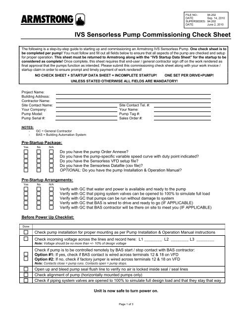
<strong>IVS</strong> <strong>Sensorless</strong> <strong>Pump</strong> <strong>Commissioning</strong> <strong>Check</strong> Sheet<br />
The following is a step-by-step guide to starting up and commissioning an <strong>Armstrong</strong> <strong>IVS</strong> <strong>Sensorless</strong> <strong>Pump</strong>. One check sheet is to<br />
be completed per pump! You must follow and fill out all fields below to ensure that all aspects of the pump are checked and setup<br />
for proper operation. This sheet must be returned to <strong>Armstrong</strong> along with the “<strong>IVS</strong> Startup Data Sheet” for the startup to be<br />
considered as complete! Once complete, this sheet requires that end-user / general contractor sign off on the work rendered as<br />
final approval that the pumps function as intended. Please submit this commissioning check sheet along with your work invoice /<br />
startup claim in order to ensure prompt and timely payment of work rendered!<br />
NO CHECK SHEET + STARTUP DATA SHEET = INCOMPLETE STARTUP!<br />
UNLESS STATED OTHERWISE ALL FIELDS ARE MANDATORY!<br />
ONE SET PER DRIVE+PUMP!<br />
Project Name:<br />
Building Address:<br />
Contractor Name:<br />
Site Contact Name: Site Contact Tel. #:<br />
Your Company:<br />
Your Name:<br />
<strong>Pump</strong> Model: <strong>Pump</strong> Tag #:<br />
<strong>Pump</strong> Serial #: Sales Order #:<br />
NOTES:<br />
- GC = General Contractor<br />
- BAS = Building Automation System<br />
Pre-Startup Package:<br />
Yes No N/A<br />
Do you have the pump Order Annexe<br />
Do you have the pump-specific variable speed curve with duty point indicated<br />
Do you have the <strong>Sensorless</strong> VFD setup file<br />
Do you have the <strong>Sensorless</strong> Datafile (csv file)<br />
OPTIONAL: Do you have the pump Installation & Operation Manual<br />
Pre-Startup Arrangements:<br />
Yes No N/A<br />
Verify with GC that water and power is available and ready to the pump<br />
Verify with GC that piping system valves can be opened to 100% to simulate full load<br />
Verify with GC that pumps can be run without damage to system<br />
Verify with GC that BAS is wired to drive and ready to go (IF APPLICABLE)<br />
Verify with GC that BAS contractor will be there on site to meet you (IF APPLICABLE)<br />
Before Power Up <strong>Check</strong>list:<br />
Done<br />
<strong>Check</strong> pump installation for proper mounting as per <strong>Pump</strong> Installation & Operation Manual instructions<br />
<strong>Check</strong> incoming voltage across the lines and record here: L1 ________ L2 ________ L3 ________<br />
Note: Voltage should be no more than +/- 10% of design voltage<br />
<strong>Check</strong> if pump is to be controlled remotely by BAS start / stop contact with BAS contractor:<br />
Option #1: If yes, check if BAS contact is wired across terminals 12 & 18 on VFD<br />
Option #2: If no, check if factory jumper is wired across terminals 12 & 18 on VFD<br />
Note: Contacts close = pump runs. Contacts open = pump stops.<br />
Open up and bleed pump seal flush line to verify no air is locked inside seal / seal lines<br />
<strong>Check</strong> alignment of pump (horizontally mounted pumps only)<br />
<strong>Check</strong> if piping system valves are opened to 100% to simulate full design load and that they stay that way<br />
Unit is now safe to turn power on.<br />
Page 1 of 3
Startup <strong>Check</strong>list:<br />
Done<br />
Verify <strong>IVS</strong> drive has completed proper bootup sequence<br />
Verify <strong>IVS</strong> drive is in the OFF mode (if not – place in OFF mode)<br />
Note: If this is a Dual Arm, make sure both <strong>IVS</strong> drives are in OFF!<br />
<strong>Check</strong> parameter 20-69.0 through 20-69.9 to verify if <strong>Sensorless</strong> data is programmed (it will show pump<br />
size, serial number, etc.)<br />
Put pump in HAND mode and run at 15Hz and looking from the top of the motor down, verify motor<br />
rotation as per the sticker on the motor (should be clockwise from top of the motor looking down)<br />
Open up and bleed pump seal flush line again to verify no air has travelled into seal / seal lines<br />
Change parameter 0-22 (default value is option 1610 – “Power [kW]”) to option 1654 “Feedback 1 [Unit]”<br />
to display <strong>Sensorless</strong> pressure readout on the top right corner of screen<br />
FOR DUAL ARMS: Close and secure the flapper valve so that it isolates the pump you are not using<br />
Close the discharge valve at the immediate outlet of the pump to deadhead pump<br />
With pump in HAND mode, increase the speed of the pump to the design speed as per the duty curve in<br />
your startup package. Eg: If your duty speed is 1550 RPM and you have a 1740 RPM, 60Hz motor, you<br />
will need to run at: 1550/1740 x 60Hz = 53.4 Hz<br />
Record the readout from suction and discharge gauges (include units)<br />
SUCTION = DISCHARGE =<br />
Verify the pump dP on deadhead (discharge valve is shut) is the same as shown on the duty curve<br />
Record VFD <strong>Sensorless</strong> pressure readout (include units)<br />
SENSORLESS PRESSURE =<br />
Verify that VFD <strong>Sensorless</strong> pressure readout is within +/- 5% compared to gauge readout<br />
Change parameter 0-22 back to option 1610 – “Power [kW]”<br />
Put pump into AUTO mode. The pump should maintain the no-flow pressure as per parameter 22-87<br />
Record VFD <strong>Sensorless</strong> pressure readout when pump is ramped down to no flow speed.<br />
Reopen discharge valve to 100% open. The pump should now ramp up to design flow and head.<br />
When pump is stabilized, record pump speed, <strong>Sensorless</strong> pressure, <strong>Sensorless</strong> flow on startup data sheet<br />
Reopen discharge valve to 100% open. The pump should now ramp up to pressure setpoint in the drive<br />
on parameter 20-21<br />
If the pump goes to full speed and does not hit the pressure setpoint, this is most likely because the<br />
system is oversized and has less resistance than designed for.<br />
Option #1: Work with general contractor and engineer to determine whether more flow and less head is<br />
acceptable. If this is, change parameter 20-21 to the new pressure setpoint, parameter 22-87 to a value<br />
that is 40% of the new setpoint and parameter 22-89 to the new flow based on the pressure setpoint<br />
according to the duty curve. RECORD THESE VALUES ON THE STARTUP DATA SHEET.<br />
Option #2: If available, try to balance the system using an <strong>Armstrong</strong> FlowTrex Valve on discharge of the<br />
pump to increase backpressure and put the pump back on the design curve<br />
Notes Regarding Dual Arm <strong>Pump</strong>s:<br />
If parameter # 5-31 on <strong>Pump</strong> #1 / Master is set to “Running / No Warning” and if both pumps are set to AUTO<br />
mode, putting one of the pumps in OFF mode will start the other pump up.<br />
If pump overlap is required when switching duty / standby pumps, go to SETUP #2 on both pumps and increase<br />
the ramp down time on parameter # 3-42. Default time is 60 seconds.<br />
<strong>Check</strong>ing for resonance:<br />
If you notice piping or accessories attached to the pump are vibrating at a specific frequency / speed of the pump, you<br />
can adjust the <strong>IVS</strong> drive to bypass this frequency by giving it a range of frequencies it needs to skip.<br />
Set the beginning of the range in parameter # 4-61 “Bypass Speed From” and the end of the range on parameter # 4-<br />
62 “Bypass Speed To”. RECORD THESE VALUES IN THE STARTUP DATA SHEET.<br />
Keep in mind that the drive does not “jump” past this range. It will just not stay within it (it will still move through it).<br />
Page 2 of 3
PID Loop Autotuning:<br />
Done<br />
Place the pump in OFF mode<br />
Verify all system valves are at 100% or a 100% load situation is recreated and nothing will change during<br />
this tuning.<br />
Change parameter 0-22 (default value is option 1610 – “Power [kW]”) to option 1654 “Feedback 1 [Unit]”<br />
to display <strong>Sensorless</strong> pressure readout on the top right corner of screen<br />
Record parameter 20-93 “PID Proportional Gain” in the Startup Data Sheet<br />
Record parameter 20-94 “PID Integral Time” in the Startup Data Sheet<br />
Verify parameter 20-95 “PID Differentiation Time” is set to “OFF”<br />
Go to parameter 20-79 “PID Auto Tuning” and change this to “ENABLE”. Follow the on-screen<br />
instructions.<br />
When the screen asks you to select a run speed where to auto tune the VFD to, use the<br />
UP/DOWN/LEFT/RIGHT keys to enter a speed where the <strong>Sensorless</strong> pressure readout (on the top right<br />
corner of the screen) is the same as the desired setpoint in parameter 20-21<br />
Press OK to begin the auto tune procedure (this can take 2-5 minutes)<br />
Press OK when auto tune is complete to accept new PID loop tuning<br />
Record NEW value in parameter 20-93 “PID Proportional Gain” in the Startup Data Sheet<br />
Record NEW value in parameter 20-94 “PID Integral Time” in the Startup Data Sheet<br />
Verify parameter 20-95 “PID Differentiation Time” is set to “OFF”<br />
Change parameter 0-22 back to option 1610 – “Power [kW]”<br />
Place the pump back into AUTO mode and then open / close discharge isolation valves to test new pump<br />
ramp up / down speeds. If acceptable, move on.<br />
BAS / BMS Communications: Yes – Type: ________________ No<br />
If the BAS/BMS is communicating to the drive via Modbus, Metasys or FLN:<br />
<strong>Check</strong> parameter # 8-30 and change it accordingly to the BAS / BMS comm. Type<br />
<strong>Check</strong> parameter # 8-31, 8-32 and 8-33 and change the address, baud rate and parity/stop bits in accordance to<br />
the BAS/BMS contractor instructions<br />
If the BAS/BMS is communicating to the drive via Lonworks or BACNet RTU, the drive is factory up already and good<br />
to go.<br />
SIGNOFF:<br />
By signing off on this startup checklist, both parties hereby accept that the equipment listed in this checklist has been<br />
properly verified to be fully operational and functioning as per the sales order for the equipment listed.<br />
Startup Technician Name (Please print):<br />
Startup Technician Signature:<br />
Customer Name (Please print):<br />
Customer Signature:<br />
Date (mm/dd/yyyy):<br />
/ / / /<br />
Date (mm/dd/yyyy):<br />
Submit complete documents to <strong>Armstrong</strong> via fax at 416-759-9101 or via email at warrantyclaims@armlink.com.<br />
S. A. <strong>Armstrong</strong> Limited <strong>Armstrong</strong> <strong>Pump</strong>s Inc. <strong>Armstrong</strong> Integrated Limited<br />
23 Bertrand Avenue 93 East Avenue Wenlock Way<br />
Toronto, Ontario North Tonawanda, New York Manchester<br />
Canada, M1L 2P3 U.S.A. 14120-6594 United Kingdom, M12 5JL<br />
T: 416-755-2291 T: 716-693-8813 T: +44 (0) 8444 145 145<br />
F: 416-759-9101 F: 716-693-8970 F: +44 (0) 8444 145 146 © S.A. <strong>Armstrong</strong> Limited 2010<br />
Page 3 of 3<br />
For <strong>Armstrong</strong> locations worldwide, please visit www.armstrongintegrated.com