10 Gigabit to 1 Gigabit Ethernet Converter (XG2G) - Cadence
10 Gigabit to 1 Gigabit Ethernet Converter (XG2G) - Cadence
10 Gigabit to 1 Gigabit Ethernet Converter (XG2G) - Cadence

You also want an ePaper? Increase the reach of your titles
YUMPU automatically turns print PDFs into web optimized ePapers that Google loves.
Technical <strong>10</strong> <strong>Gigabit</strong> Data <strong>to</strong> Sheet 1 <strong>Gigabit</strong> <strong>Ethernet</strong><br />
<strong>Converter</strong> (<strong>XG2G</strong>)<br />
Technical Data Sheet<br />
Part Number:<br />
T-CS-ET-0023-<strong>10</strong>0<br />
Document Number: I-IPA01-0213-USR Rev 06<br />
March 2011<br />
i
<strong>10</strong> <strong>Gigabit</strong> <strong>to</strong> 1 <strong>Gigabit</strong> <strong>Ethernet</strong> <strong>Converter</strong> (<strong>XG2G</strong>)<br />
©2004-2011 <strong>Cadence</strong> Design Systems, Inc. All rights reserved<br />
Proprietary Notice<br />
In the U.S. and numerous other countries, <strong>Cadence</strong> and the <strong>Cadence</strong> logo are registered<br />
trademarks and <strong>Cadence</strong> Design Foundry is a trademark of <strong>Cadence</strong> Design Systems, Inc.<br />
All other products or services mentioned herein may be trademarks of their respective<br />
owners.<br />
Neither the whole nor any part of the information contained in, or the product described in<br />
this document may be adapted or reproduced in any material form except with the prior<br />
written permission of the copyright owner.<br />
The product described in this document is subject <strong>to</strong> continuous developments and<br />
improvements and is supplied "AS IS". All warranties implied or expressed including but not<br />
limited <strong>to</strong> implied warranties or merchantability, or fitness for purpose, are excluded.<br />
<strong>Cadence</strong> Design Foundry, Inc shall not be liable for any loss or damage arising from the use<br />
of any information in this document, or any error or omission in such information, or any<br />
incorrect use of the product. <strong>Cadence</strong> Design Foundry products are not authorized for use as<br />
critical components in life support devices or systems without the express written approval of<br />
an authorised officer of <strong>Cadence</strong> Design Foundry, Inc. As used herein:<br />
1. Life support devices or systems are devices of systems that are (a) intended for surgical<br />
implant in<strong>to</strong> the body or (b) support or sustain life, and whose failure <strong>to</strong> perform, when<br />
properly used in accordance with instructions for use provided in the labeling, can be<br />
reasonably expected <strong>to</strong> result in a significant injury <strong>to</strong> the user.<br />
2. A critical component is any component of a life support device or system or system<br />
whose failure <strong>to</strong> perform can reasonably be expected <strong>to</strong> cause the failure of the life<br />
support device or system, or <strong>to</strong> affect its safety or effectiveness.<br />
Document No: I-IPA01-0213-USR Rev 06, March 2011<br />
© 2004-2011 <strong>Cadence</strong> Design Systems, Inc. Page ii
<strong>XG2G</strong> Technical Data Sheet<br />
Features<br />
• Converts between XGMII and GMII interfaces <strong>to</strong> allow a <strong>10</strong> Gig <strong>Ethernet</strong> MAC <strong>to</strong><br />
operate in a gigabit environment.<br />
• Also converts between XGMII and MII interfaces <strong>to</strong> allow a <strong>10</strong> Gig <strong>Ethernet</strong> MAC <strong>to</strong><br />
operate in a <strong>10</strong>/<strong>10</strong>0M environment.<br />
• Interfaces <strong>to</strong> demultiplexed IEEE 802.3 XGMII (uses 64 bit wide data sampled on<br />
single clock edge rather than 32 bit wide data sampled on both edges of the clock).<br />
• Interfaces <strong>to</strong> standard IEEE 802.3 GMII or IEEE 802.3 MII.<br />
• Supports <strong>10</strong>, <strong>10</strong>0 and <strong>10</strong>00 Megabit per second speeds of operation.<br />
• Also supports <strong>10</strong>0 Megabit per second SGMII operation (where every GMII data byte<br />
is repeated ten times).<br />
• Supports transport of 802.3az low power idle indication.<br />
Description<br />
The <strong>XG2G</strong> wrapper allows a <strong>10</strong> Gig MAC <strong>to</strong> operate at <strong>10</strong>, <strong>10</strong>0 and <strong>10</strong>00Mb/s data rates in<br />
addition <strong>to</strong> <strong>10</strong> Gb/s. The <strong>XG2G</strong> can operate in either GMII mode or MII mode. Using the<br />
<strong>XG2G</strong> in GMII mode a <strong>10</strong>G <strong>Ethernet</strong> MAC, clocked at 15.625MHz, can be connected <strong>to</strong> a 1G<br />
<strong>Ethernet</strong> Physical Layer using GMII clocked at 125MHz. In MII mode connection can be<br />
made <strong>to</strong> a <strong>10</strong>/<strong>10</strong>0 PHY using MII. The <strong>XG2G</strong> performs all the conversions required <strong>to</strong> map<br />
XGMII signalling in<strong>to</strong> GMII/MII signalling and vice versa. The <strong>XG2G</strong> performs error handling<br />
<strong>to</strong> ensure errors are detected and handled correctly.<br />
It also supports a <strong>10</strong>0Mb/s SGMII mode of operation where the <strong>10</strong>G <strong>Ethernet</strong> MAC is<br />
clocked at 1.5625MHz. In this mode each byte on the 125MHz GMII interface is repeated ten<br />
times in accordance with the SGMII specification. This increases the number of symbols in<br />
each frame by a fac<strong>to</strong>r of ten. The XAUI CTC has been shown still <strong>to</strong> be effective in <strong>10</strong>0Mb/s<br />
mode with a <strong>10</strong>0 ppm difference between the recovered and local clock.<br />
Operation<br />
The <strong>XG2G</strong> operates au<strong>to</strong>nomously. It does not require an external input <strong>to</strong> restart it in error<br />
conditions.<br />
The transmit path transfers the data (64 bits) from the MAC clock (tx_slow_clk) <strong>to</strong> the<br />
GMII/MII clock (tx_fast_clk). The data is then serialised (by byte in GMII mode or by a 4-bit<br />
nibble in MII mode) and mapped in<strong>to</strong> the GMII/MII packet format (SOP converted <strong>to</strong><br />
preamble and EOP converted <strong>to</strong> idle and gmii_tx_en and gmii_tx_er set accordingly).<br />
The <strong>XG2G</strong> also ensures a minimum Inter-Packet Gap (IPG) of 96 bits on the GMII/MII. This<br />
requires the buffering of data from the XGMII and a guaranteed average IPG on the XGMII of<br />
12 symbols with a minimum IPG of 8 symbols. If the XGMII IPG does not meet these<br />
requirements then the <strong>XG2G</strong> transmit buffer will overflow and the packet in progress is<br />
terminated<br />
In GMII mode the ratio between the slow clocks and fast clock is 1:8 while in MII mode it is<br />
1:16. In <strong>10</strong>0 Megabit per second SGMII mode the ratio is 1:80.<br />
The receive path takes the data from the 1G/<strong>10</strong>0M Physical Interface and transforms it in<strong>to</strong><br />
XGMII formatted packets. Any packet which does not start with gmii_rxd == SFD (Start of<br />
Document No: I-IPA01-0213-USR Rev 06, March 2011<br />
© 2004-2011 <strong>Cadence</strong> Design Systems, Inc. Page 3
<strong>XG2G</strong> Technical Data Sheet<br />
Frame Delimiter), gmii_rx_dv == 1 and gmii_rx_er == 0 is not transformed and the data is<br />
dropped. The <strong>XG2G</strong> internally reconstructs the preamble and ensures that incoming<br />
GMII/MII frames that suffer preamble erosion are not rejected by the receiving <strong>10</strong>G MAC.<br />
The reconstruction process prepends preamble symbols (0x55) on<strong>to</strong> frames that have short<br />
preamble (it also strips any preamble in excess of seven bytes). The process is<br />
non-destructive in GMII mode, so non-standard preamble is preserved.<br />
In MII mode the <strong>XG2G</strong> performs nibble <strong>to</strong> byte (RX) and byte <strong>to</strong> nibble (TX) conversion and<br />
re-uses the GMII data path logic in order <strong>to</strong> translate MII frames in<strong>to</strong> XGMII and vice versa.<br />
The GMII data path logic in this case is timed <strong>to</strong> every second fast clock, because it needs<br />
1:8 clock ratio between the slow and the fast clock domain.<br />
The nibble-byte and byte-nibble conversion logic is timed on every fast clock (16 times the<br />
slow clock rate). This logic takes care of SFD recognition and alignment, which is necessary<br />
because the number of nibbles (odd or even) forming the preamble is unknown. The<br />
preamble (if any) in MII mode is effectively lost, and reconstructed fully along the GMII data<br />
path logic within the <strong>XG2G</strong>.<br />
The <strong>XG2G</strong> handles an excess nibble condition on the receive path in MII mode in the<br />
following way. If the excess nibble is marked as error (gmii_rx_er is asserted high), the<br />
<strong>XG2G</strong> rounds the nibble <strong>to</strong> a full octet and converts it <strong>to</strong> an error symbol on the XGMII. Thus<br />
the MAC would be notified for a symbol error. If the excess nibble is not marked as error<br />
(gmii_rx_er is not asserted and remains low) the <strong>XG2G</strong> would truncate the frame, essentially<br />
discarding the excess nibble. The MAC would accept the frame only if its CRC is correct.<br />
The <strong>XG2G</strong> transports 802.3az LPI indication. XGMII normal idle (any byte of xgmii_txd[63:0]<br />
== 0x07 with the corresponding bit of xgmii_txc[7:0] == 1) is converted <strong>to</strong> GMII/MII idle<br />
(gmii_txd
<strong>XG2G</strong> Technical Data Sheet<br />
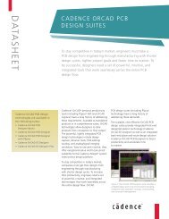
Block Diagram<br />
Clock Domains<br />
÷ 8 (GMII)<br />
or<br />
÷ 16 (MII)<br />
tx_fast_clk 125MHz - GMII<br />
25MHz - MII<br />
<strong>10</strong>G MAC TX Path<br />
xg2g<br />
TX Slow<br />
Phase Buffer<br />
TX <strong>to</strong><br />
GMII<br />
GMII <strong>to</strong> MII<br />
(byte <strong>to</strong> nibble)<br />
<strong>10</strong>G MAC RX Path<br />
xg2g<br />
RX Slow<br />
Phase Buffer<br />
GMII<br />
<strong>to</strong> RX<br />
MII <strong>to</strong> GMII<br />
(nibble <strong>to</strong> byte,<br />
SFD alignment,<br />
Excess nibble<br />
condition<br />
handling)<br />
÷ 8 (GMII)<br />
or<br />
÷ 16 (MII)<br />
rx_fast_clk 125MHz - GMII<br />
25MHz - MII<br />
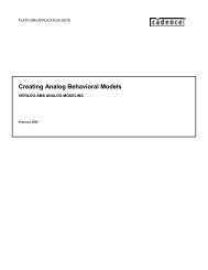
Transmit Datapath<br />
15.625MHz Transmit Clock div 8<br />
(GMII), or<br />
1.5625MHz Transmit Clock div 16<br />
(MII)<br />
Slow Clock<br />
sync genera<strong>to</strong>r<br />
125MHz Transmit Clock (GMII), or<br />
25MHz Transmit Clodk (MII)<br />
Data pops<br />
control logic<br />
(every 8th<br />
clock cycle)<br />
buffer depth is 3<br />
Cycle through data<br />
and insert sufficient<br />
IPG. As the IPG is<br />
inserted a byte at a<br />
time this is the<br />
mode least likely <strong>to</strong><br />
cause buffer<br />
problems<br />
XGMII Data<br />
Stream<br />
64 bit Data<br />
and<br />
8 bit Control<br />
S<strong>to</strong>re only data<br />
as IPG is<br />
inserted later<br />
Data pass through,<br />
SOP/EOP translation,<br />
or IPG Genera<strong>to</strong>r<br />
GMII or MII<br />
data stream<br />
IPG counter <strong>to</strong> ensure<br />
minimum IPG is always<br />
provided<br />
Document No: I-IPA01-0213-USR Rev 06, March 2011<br />
© 2004-2011 <strong>Cadence</strong> Design Systems, Inc. Page 5
<strong>XG2G</strong> Technical Data Sheet<br />
Receive Datapath<br />
125MHz Receive Clock (GMII),<br />
or<br />
25MHz Receive Clock (MII)<br />
15.625MHz Receive Clock div 8<br />
(GMII), or<br />
1.5625MHz Receive Clock div 16<br />
(MII)<br />
Cyclical<br />
Ordering<br />
Data push<br />
control logic<br />
(every 8th clock<br />
cycle)<br />
Slow Clock<br />
sync genera<strong>to</strong>r<br />
7<br />
-3<br />
GMII or MII<br />
data stream<br />
Preamble reconstruction<br />
SOP/EOP<br />
Detection<br />
and<br />
conversion<br />
6<br />
5<br />
4<br />
3<br />
2<br />
1<br />
-2<br />
-1<br />
0<br />
-3<br />
-2<br />
-1<br />
Data<br />
ordering<br />
control<br />
logic<br />
SOP<br />
64 bit Data<br />
and<br />
8 bit Control<br />
XGMII Data<br />
Stream<br />
0<br />
0<br />
SOP<br />
idle<br />
change<br />
for<br />
reseting<br />
SOP<br />
position<br />
Samples<br />
Data<br />
every<br />
clock<br />
cycle<br />
Document No: I-IPA01-0213-USR Rev 06, March 2011<br />
© 2004-2011 <strong>Cadence</strong> Design Systems, Inc. Page 6
<strong>XG2G</strong> Technical Data Sheet<br />
Signal Interfaces<br />
The <strong>XG2G</strong> includes the following signal interfaces:<br />
• <strong>XG2G</strong> specific clock and reset signals<br />
• XGMII (demultiplexed)<br />
• GMII<br />
• GMII/MII mode select<br />
• <strong>10</strong>0 Megabit SGMII mode select<br />
Clock Domains<br />
The <strong>XG2G</strong> contains 4 clock domains. Frequency is shown for GMII/MII mode of operation.<br />
1) Low Speed Transmit Domain tx_slow_clk (15.625MHz 1.5625MHz 0.15625MHz)<br />
2) High Speed transmit Domain tx_fast_clk (125MHz 25MHz 2.5MHz)<br />
3) Low Speed Receive Domain rx_slow_clk (15.625MHz 1.5625MHz 0.15625MHz)<br />
4) High Speed Receive Domain rx_fast_clk (125MHz 25MHz 2.5MHz)<br />
Clock domain (1) must be derived from clock domain (2): via division by 8 (GMII) or 16 (MII).<br />
Clock domain (3) must be derived from clock domain (4): via division by 8 (GMII) or 16 (MII).<br />
Signal Name Direction Function<br />
tx_fast_clk Input High speed GMII/MII transmit clock<br />
(125MHz/25MHz/2.5MHz)<br />
txf_rst_n Input Active low tx_fast_clk domain reset. This signal should<br />
be asserted low asynchronously, and deasserted high<br />
synchronously with tx_fast_clk.<br />
tx_slow_clk Input Slow speed XGMII transmit clock (15.625MHz/1.5625MHz/<br />
0.15625MHz)<br />
txs_rst_n Input Active low tx_slow_clk domain reset. This signal should<br />
be asserted low asynchronously, and deasserted high<br />
synchronously with tx_slow_clk.<br />
rx_fast_clk Input High speed GMII/MII receive clock (125MHz/25MHz/2.5MHz)<br />
rxf_rst_n Input Active low rx_fast_clk domain reset. This signal should<br />
be asserted low asynchronously, and deasserted high<br />
synchronously with rx_fast_clk.<br />
rx_slow_clk Input Slow speed XGMII receive clock (15.625MHz/1.5625MHz/ /<br />
0.15625MHz)<br />
rxs_rst_n Input Active low rx_slow_clk domain reset. This signal should<br />
be asserted low asynchronously, and deasserted high<br />
synchronously with rx_slow_clk.<br />
Document No: I-IPA01-0213-USR Rev 06, March 2011<br />
© 2004-2011 <strong>Cadence</strong> Design Systems, Inc. Page 7
<strong>XG2G</strong> Technical Data Sheet<br />
XGMII (demultiplexed) Signals<br />
The XGMII is non-DDR so 64 bits of data and 8 bits of control are transferred on the rising<br />
edge of the XGMII clock.<br />
Signal Name Direction Function<br />
xgmii_txd[63:0] Input 8 bytes of data <strong>to</strong> be transmitted over the GMII<br />
xgmii_txc[7:0] Input 8 control bits (one per byte of xgmii_txd) defining data or<br />
control information for the remainder<br />
xgmii_rxd[63:0] Output 8 bytes of data received from the GMII<br />
xgmii_rxc[7:0] Output 8 control bits (one per byte of xgmii_rxd) defining data or<br />
control information for the remainder<br />
GMII/MII Signals<br />
The GMII meets the requirements set in IEEE 802.3. In MII mode only bits 3 down<strong>to</strong> 0 are<br />
used from the data buses, gmii_rxd[7:4] should not be left unconnected however.<br />
Signal Name Direction Function<br />
gmii_txd[7:0] Output Data <strong>to</strong> be transmitted by the physical layer<br />
gmii_tx_en Output Flag indicating valid data on gmii_txd.<br />
gmii_tx_er Output Flag indicating an error on gmii_txd<br />
gmii_rxd[7:0] Input Data received from the physical layer<br />
gmii_rx_dv Input Flag indicating valid data on gmii_rxd<br />
gmii_rx_er Input Flag indicating an error on gmii_rxd<br />
GMII/MII Mode Select Signal<br />
This signal sets the mode of operation of the <strong>XG2G</strong>, i.e. GMII or MII. It is considered a static<br />
control signal and should not be changed during normal operation of the device. The <strong>XG2G</strong><br />
relies on a particular clock ratio between the fast and slow clock domains. In GMII mode this<br />
ratio must be 8, whereas in MII mode this ratio must be 16.<br />
Signal Name Direction Function<br />
mii_mode Input 0 – GMII mode of operation; 1 – MII mode of operation<br />
SGMII <strong>10</strong>0 Megabit Mode Select Signal<br />
This signal sets the <strong>10</strong>0 Mbps SGMII mode of operation. It is considered a static control<br />
signal and should not be changed during normal operation of the device. The <strong>XG2G</strong> relies on<br />
a particular clock ratio between the fast and slow clock domains. In SGMII <strong>10</strong>0M mode this<br />
ratio must be 80. The mii_mode input must be low when sgmii_mode_<strong>10</strong>0m is asserted.<br />
When SGMII <strong>10</strong>0M mode is selected the GMII clocks run at 125MHz and the XGMII clocks at<br />
1.5625MHz. Each GMII data byte is repeated ten times resulting in an effective frame length<br />
increase of a fac<strong>to</strong>r of ten. This puts an extra burden on any clock <strong>to</strong>lerance correction<br />
circuitry in the receive path.<br />
Signal Name Direction Function<br />
sgmii_mode_<strong>10</strong>0m Input 1 – <strong>10</strong>0 Meg SGMII operation; 0 – normal operation<br />
Document No: I-IPA01-0213-USR Rev 06, March 2011<br />
© 2004-2011 <strong>Cadence</strong> Design Systems, Inc. Page 8
<strong>XG2G</strong> Technical Data Sheet<br />
Programming Interface<br />
This device does not require programming.<br />
Physical Estimates<br />
Gate count<br />
9,600 Gates – NAND2 equivalents<br />
FF count 880<br />
Pin count 175<br />
Power consumption 1mW typical for TSMC 0.13G<br />
Verification<br />
All our IP modules are verified <strong>to</strong> one of the following levels:<br />
• Gold IP has been <strong>to</strong> target silicon.<br />
• Silver IP has been <strong>to</strong> silicon in FPGA.<br />
• Bronze IP has been verified in simulation with logical timing closure.<br />
• In development IP has not yet been verified.<br />
Please contact the IPGallery (ipgallery@cadence.com) for the latest verification<br />
information.<br />
Deliverables<br />
The full IP package comes complete with:<br />
• Verilog HDL<br />
• <strong>Cadence</strong> RTL Compiler synthesis scripts with SDC constraints<br />
• Verilog testbench<br />
• <strong>XG2G</strong> User’s Guide with IP integration and synthesis instructions.<br />
Document No: I-IPA01-0213-USR Rev 06, March 2011<br />
© 2004-2011 <strong>Cadence</strong> Design Systems, Inc. Page 9