Installation Instructions - Vivid Racing
Installation Instructions - Vivid Racing
Installation Instructions - Vivid Racing

Create successful ePaper yourself
Turn your PDF publications into a flip-book with our unique Google optimized e-Paper software.
21. Torque the factory pivot bolts to the crossmember to 96 ft<br />
lbs on 1988-1990 and 120 ft lbs on 1991-1998 models.<br />
Toque the LCA pivot bolt to 125 ft lbs.<br />
22. Locate the new extended brake line kit FTS1500-9.<br />
Remove the banjo bolt securing the brake line to the<br />
caliper. Separate the hard line section from the rubber<br />
brake line at the frame. Remove the clip holding the rubber<br />
brake line to the frame tab and set aside. Insert the new<br />
brake line into the frame mount tab and reinstall the clip.<br />
Using the supplied crush washers attach the end of the<br />
brake line with the banjo fitting to the caliper. Be sure<br />
there is a crush washer on each side of the banjo fitting and<br />
the old washer is not still attached to the bolt or caliper. Do<br />
not over tighten the banjo bolt. Attach the factory hard line<br />
to the upper fitting on the new brake line. Tighten the<br />
upper fitting on the new brake line. You will now need to<br />
bleed the brakes per the factory shop manual.<br />
23. Reinstall the factory ABS / Dust Shield to the lift spindle<br />
using the factory hardware. The ABS wire will be<br />
positioned under the tie rod end routed up the backside of<br />
the control arm. Reinstall the brake rotor onto the lift<br />
spindle using the factory hardware. REPACK THE<br />
WHEEL BEARINGS WITH HEAVY DUTY WHEEL<br />
BEARING GREASE AT THIS TIME. Reinstall the<br />
brake caliper onto the spindle, use thread locking<br />
compound on the caliper bracket bolts and torque 1988-<br />
1991 models to 28ft/lbs and 1992-1998 models to 38 ft. lbs.<br />
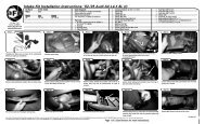
Using two of the supplied adel clamps attach the brake line<br />
and the ABS line to the back side of the spindle. SEE<br />
PHOTO BELOW.<br />
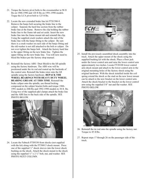
25. Install the previously assembled shock assembly into the<br />
truck. Attach the upper mount of the shock using the<br />
supplied bushing kit with the shock. Place a floor jack<br />
under the lower control arm and raise the lower control arm<br />
approximately two inches. Locate FT20188 lower control<br />
arm shock mount and attach to the lower control arm in the<br />
original mounting holes of the factory shock using the<br />
original hardware. With the shock installed inside the coil<br />
spring extend the shock so the stud on the new lower mount<br />
can be attach to the new bracket on the lower control arm.<br />
Attach the shock bracket to the bracket on the lower control<br />
arm using the supplied 3/8” nut and flat washer. SEE<br />
PHOTO BELOW.<br />
26. Reinstall the tie rod onto the spindle using the factory nut.<br />
Torque to 45 ft/lbs.<br />
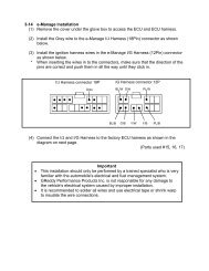
24. Locate the Fabtech FTS9330 front shocks (not supplied<br />
with the kit) along with the FT50013 shock mount. Press<br />
one of the supplied ½” shock sleeves into the lower shock<br />
bushing on the shock. Attach the shock mount to the shock<br />
using the supplied ½” x 2 ¾” bolt, nut, and washer. SEE<br />
PHOTO NEXT COLUMN.<br />
27. Repeat steps 17 through 26 on the passenger side of the<br />
truck.