Thermally developing flow and heat transfer in rectangular ...
Thermally developing flow and heat transfer in rectangular ...
Thermally developing flow and heat transfer in rectangular ...

Create successful ePaper yourself
Turn your PDF publications into a flip-book with our unique Google optimized e-Paper software.
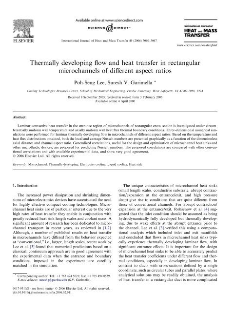
International Journal of Heat <strong>and</strong> Mass Transfer 49 (2006) 3060–3067<br />
www.elsevier.com/locate/ijhmt<br />
<strong>Thermally</strong> <strong>develop<strong>in</strong>g</strong> <strong>flow</strong> <strong>and</strong> <strong>heat</strong> <strong>transfer</strong> <strong>in</strong> <strong>rectangular</strong><br />
microchannels of different aspect ratios<br />
Poh-Seng Lee, Suresh V. Garimella *<br />
Cool<strong>in</strong>g Technologies Research Center, School of Mechanical Eng<strong>in</strong>eer<strong>in</strong>g, Purdue University, West Lafayette, IN 47907-2088, USA<br />
Received 8 September 2005; received <strong>in</strong> revised form 3 February 2006<br />
Available onl<strong>in</strong>e 4 April 2006<br />
Abstract<br />
Lam<strong>in</strong>ar convective <strong>heat</strong> <strong>transfer</strong> <strong>in</strong> the entrance region of microchannels of <strong>rectangular</strong> cross-section is <strong>in</strong>vestigated under circumferentially<br />
uniform wall temperature <strong>and</strong> axially uniform wall <strong>heat</strong> flux thermal boundary conditions. Three-dimensional numerical simulations<br />
were performed for lam<strong>in</strong>ar thermally <strong>develop<strong>in</strong>g</strong> <strong>flow</strong> <strong>in</strong> microchannels of different aspect ratios. Based on the temperature <strong>and</strong><br />
<strong>heat</strong> flux distributions obta<strong>in</strong>ed, both the local <strong>and</strong> average Nusselt numbers are presented graphically as a function of the dimensionless<br />
axial distance <strong>and</strong> channel aspect ratio. Generalized correlations, useful for the design <strong>and</strong> optimization of microchannel <strong>heat</strong> s<strong>in</strong>ks <strong>and</strong><br />
other microfluidic devices, are proposed for predict<strong>in</strong>g Nusselt numbers. The proposed correlations are compared with other conventional<br />
correlations <strong>and</strong> with available experimental data, <strong>and</strong> show very good agreement.<br />
Ó 2006 Elsevier Ltd. All rights reserved.<br />
Keywords: Microchannel; <strong>Thermally</strong> <strong>develop<strong>in</strong>g</strong>; Electronics cool<strong>in</strong>g; Liquid cool<strong>in</strong>g; Heat s<strong>in</strong>k<br />
1. Introduction<br />
The <strong>in</strong>creased power dissipation <strong>and</strong> shr<strong>in</strong>k<strong>in</strong>g dimensions<br />
of microelectronics devices have accentuated the need<br />
for highly effective compact cool<strong>in</strong>g technologies. Microchannel<br />
<strong>heat</strong> s<strong>in</strong>ks are of particular <strong>in</strong>terest due to the very<br />
high rates of <strong>heat</strong> <strong>transfer</strong> they enable <strong>in</strong> conjunction with<br />
greatly reduced <strong>heat</strong> s<strong>in</strong>k length scales <strong>and</strong> coolant mass. A<br />
significant amount of research has been dedicated to microchannel<br />
transport <strong>in</strong> recent years, as reviewed <strong>in</strong> [1,2].<br />
Although, a number of published results on <strong>heat</strong> <strong>transfer</strong><br />
<strong>in</strong> microchannels have differed from the behavior expected<br />
at ‘‘conventional,’’ i.e., larger, length scales, recent work by<br />
Lee et al. [3] found that numerical predictions based on a<br />
classical, cont<strong>in</strong>uum approach are <strong>in</strong> good agreement with<br />
the experimental data when the entrance <strong>and</strong> boundary<br />
conditions imposed <strong>in</strong> the experiment are carefully<br />
matched <strong>in</strong> the simulation.<br />
* Correspond<strong>in</strong>g author. Tel.: +1 765 494 5621; fax: +1 765 494 0539.<br />
E-mail address: sureshg@purdue.edu (S.V. Garimella).<br />
The unique characteristics of microchannel <strong>heat</strong> s<strong>in</strong>ks<br />
(small length scales, conductive substrate, abrupt contraction/expansion<br />
at the entrance/exit, <strong>and</strong> high pressure<br />
drop) give rise to conditions that are quite different from<br />
those of conventional channels. For abrupt contraction/<br />
expansion at the entrance/exit, Rohsenow et al. [4] suggested<br />
that the <strong>in</strong>let condition should be assumed as be<strong>in</strong>g<br />
hydrodynamically fully developed but thermally <strong>develop<strong>in</strong>g</strong>,<br />
due to wake effects at the abrupt entrance prior to<br />
the channel. Lee et al. [3] verified this us<strong>in</strong>g a computational<br />
analysis which <strong>in</strong>cluded <strong>in</strong>let <strong>and</strong> exit manifolds<br />
<strong>and</strong> concluded that <strong>flow</strong>s <strong>in</strong> microchannel <strong>heat</strong> s<strong>in</strong>ks typically<br />
experience thermally <strong>develop<strong>in</strong>g</strong> lam<strong>in</strong>ar <strong>flow</strong>, with<br />
significant entrance effects. It is important for the design<br />
of microchannel <strong>heat</strong> s<strong>in</strong>ks to be able to accurately predict<br />
the <strong>heat</strong> <strong>transfer</strong> coefficients under different <strong>flow</strong> <strong>and</strong> thermal<br />
conditions, especially <strong>in</strong> <strong>develop<strong>in</strong>g</strong> lam<strong>in</strong>ar <strong>flow</strong>. In<br />
contrast to ducts with cross-sections def<strong>in</strong>ed by a s<strong>in</strong>gle<br />
coord<strong>in</strong>ate, such as circular tubes <strong>and</strong> parallel plates, where<br />
analytical solutions may be readily obta<strong>in</strong>ed, the analysis<br />
of <strong>heat</strong> <strong>transfer</strong> <strong>in</strong> a <strong>rectangular</strong> duct is more complicated<br />
0017-9310/$ - see front matter Ó 2006 Elsevier Ltd. All rights reserved.<br />
doi:10.1016/j.ij<strong>heat</strong>mass<strong>transfer</strong>.2006.02.011
P.-S. Lee, S.V. Garimella / International Journal of Heat <strong>and</strong> Mass Transfer 49 (2006) 3060–3067 3061<br />
Nomenclature<br />
a channel width, lm<br />
b channel height, lm<br />
c p specific <strong>heat</strong>, kJ/kg °C<br />
D h hydraulic diameter, lm<br />
h convective <strong>heat</strong> <strong>transfer</strong> coefficient, W/m 2 °C<br />
k thermal conductivity, W/m °C<br />
l channel length, mm<br />
_m mass <strong>flow</strong> rate, kg/s<br />
n <strong>in</strong>dex<br />
Nu Nusselt number (Nu = hD h /k)<br />
p pressure, N/m 2<br />
Pr Pr<strong>and</strong>tl number (Pr = lc p /k)<br />
q 00 <strong>heat</strong> flux, W/m 2<br />
R 2 correlation coefficient<br />
Re channel Reynolds Number (Re = quD h /l)<br />
T temperature, °C<br />
u velocity, m/s<br />
x x-coord<strong>in</strong>ate, mm<br />
y y-coord<strong>in</strong>ate, mm<br />
z z-coord<strong>in</strong>ate (axial distance), mm<br />
thermal entrance length, mm<br />
dimensionless axial distance (z = z/ReD h Pr)<br />
z th<br />
dimensionless thermal entrance length<br />
ðz th ¼ z th=ReD h PrÞ<br />
z th<br />
z <br />
Greek symbols<br />
a channel aspect ratio (a = b/a)<br />
d thickness of the th<strong>in</strong> microchannel wall, lm<br />
q density of water, kg/m 3<br />
l dynamic viscosity, Ns/m 2<br />
1 fully developed<br />
Subscripts<br />
ave average<br />
f fluid<br />
fd fully developed <strong>flow</strong><br />
m mean<br />
z local<br />
w wall<br />
<strong>and</strong> most studies have employed numerical approaches<br />
[5,6].<br />
Accurate prediction of <strong>heat</strong> <strong>transfer</strong> coefficients also<br />
requires the correct thermal boundary conditions to be<br />
faithfully simulated. In applications where microchannel<br />
<strong>heat</strong> s<strong>in</strong>ks are used, a uniform <strong>heat</strong> flux is usually applied<br />
to the base of the <strong>heat</strong> s<strong>in</strong>k substrate, which is often made<br />
of a conductive material such as silicon, copper or alum<strong>in</strong>um<br />
to reduce overall thermal resistances. Three-dimensional<br />
conjugate <strong>heat</strong> <strong>transfer</strong> thus takes place with<strong>in</strong> the<br />
<strong>heat</strong> s<strong>in</strong>k, lead<strong>in</strong>g to the redistribution of <strong>heat</strong> flux <strong>and</strong><br />
temperature along the channel walls. Though three-dimensional<br />
conjugate <strong>heat</strong> <strong>transfer</strong> analyses have been shown to<br />
provide satisfactory simulations of experimental conditions<br />
[3,7], they are computationally expensive <strong>and</strong> case-specific,<br />
<strong>and</strong> cannot be generalized to a wide range of microchannel<br />
configurations. To simplify the full three-dimensional conjugate<br />
analysis, the computational doma<strong>in</strong> has typically<br />
been restricted to <strong>in</strong>clude only the fluid region, with one<br />
of the follow<strong>in</strong>g alternative thermal boundary conditions<br />
applied to the channel walls: H1 (circumferentially constant<br />
wall temperature <strong>and</strong> axially constant wall <strong>heat</strong> flux),<br />
H2 (uniform wall <strong>heat</strong> flux, both axially <strong>and</strong> circumferentially),<br />
<strong>and</strong> T (uniform wall temperature, both axially <strong>and</strong><br />
circumferentially) [8]. While all the details of the actual<br />
thermal problem are not faithfully represented by means<br />
of these simplifications, such approaches are more computationally<br />
economical s<strong>in</strong>ce conduction <strong>in</strong> the substrate is<br />
not <strong>in</strong>cluded <strong>in</strong> the calculation procedure. Importantly,<br />
the results of such analyses can be generalized to microchannels<br />
of different dimensions, de-coupled from details<br />
of the substrate.<br />
Lee et al. [3] conducted a detailed, three-dimensional<br />
conjugate <strong>heat</strong> <strong>transfer</strong> analysis for the copper microchannel<br />
<strong>heat</strong> s<strong>in</strong>k used <strong>in</strong> their work (with a uniform <strong>heat</strong> flux<br />
imposed on the bottom wall of the substrate). They compared<br />
the results from their analysis to those obta<strong>in</strong>ed from<br />
simplified analyses for a microchannel us<strong>in</strong>g the H1, H2<br />
<strong>and</strong> T boundary conditions on the channel wall. With the<br />
three-dimensional conjugate <strong>heat</strong> <strong>transfer</strong> model, a computational<br />
grid of 50 · 160 · 100 cells had to be used, whereas<br />
for the simplified analyses only an eighth of the grid size<br />
(20 · 50 · 100 cells) was required. Predictions from the<br />
H1 thermal boundary condition were found to be <strong>in</strong> the<br />
best agreement with the full three-dimensional conjugate<br />
analysis, deviat<strong>in</strong>g by less than 1.3%. They concluded that<br />
the H1 thermal boundary condition is the most appropriate<br />
for simplified analyses, when full conjugate analyses are<br />
not affordable. The H1 thermal boundary condition is<br />
common <strong>in</strong> eng<strong>in</strong>eer<strong>in</strong>g problems such as electric resistance<br />
<strong>heat</strong><strong>in</strong>g, nuclear <strong>heat</strong><strong>in</strong>g, counter<strong>flow</strong> <strong>heat</strong> exchangers hav<strong>in</strong>g<br />
nearly identical fluid capacity rates, all with highly conductive<br />
wall materials [9].<br />
Wibulswas [5] solved the thermal entrance length problem<br />
with the H1 boundary condition; fluid axial conduction<br />
<strong>and</strong> viscous dissipation were neglected <strong>and</strong> it was<br />
assumed that no <strong>heat</strong> sources were present <strong>in</strong> the doma<strong>in</strong>.<br />
Aparecido <strong>and</strong> Cotta [6] solved the problem of thermally<br />
<strong>develop<strong>in</strong>g</strong> <strong>flow</strong> <strong>in</strong> square ducts for the T boundary condition.<br />
However, both these sets of results were limited to a<br />
small range of channel aspect ratios (a = 1–4), <strong>and</strong> were<br />
also restricted by the available computational resources<br />
of the time. With the <strong>in</strong>creased power of the modern computer,<br />
much improved computational fluid dynamics
3062 P.-S. Lee, S.V. Garimella / International Journal of Heat <strong>and</strong> Mass Transfer 49 (2006) 3060–3067<br />
(CFD) computations can be performed with high accuracy<br />
<strong>and</strong> flexibility.<br />
In the present work, lam<strong>in</strong>ar <strong>flow</strong> <strong>and</strong> <strong>heat</strong> <strong>transfer</strong> <strong>in</strong><br />
the thermal entrance region of <strong>rectangular</strong> ducts with<br />
aspect ratios rang<strong>in</strong>g from 1 to 10 is <strong>in</strong>vestigated for thermally<br />
<strong>develop<strong>in</strong>g</strong> <strong>flow</strong> with the H1 thermal boundary condition.<br />
A f<strong>in</strong>ite volume approach is employed to obta<strong>in</strong> the<br />
temperature <strong>and</strong> <strong>heat</strong> flux distributions on the channel<br />
walls. The local <strong>and</strong> average Nusselt numbers <strong>in</strong> the<br />
entrance region are numerically calculated as functions of<br />
the dimensionless axial distance <strong>and</strong> channel aspect ratio.<br />
Generalized correlations for both the local <strong>and</strong> average<br />
Nusselt numbers <strong>in</strong> the thermal entrance region are proposed.<br />
The results are compared to predictions from correlations<br />
for conventional channels as well as with<br />
experimental data for microchannels, <strong>and</strong> good agreement<br />
is noted. The proposed correlations are easy to use, provide<br />
detailed <strong>heat</strong> <strong>transfer</strong> coefficient predictions <strong>in</strong> the entrance<br />
region of microchannels, <strong>and</strong> cover a wide parameter<br />
range.<br />
2. Mathematical formulation<br />
The follow<strong>in</strong>g assumptions are made to model the <strong>heat</strong><br />
<strong>transfer</strong> <strong>in</strong> the <strong>rectangular</strong> channel:<br />
(1) steady state,<br />
(2) <strong>in</strong>compressible fluid,<br />
(3) lam<strong>in</strong>ar <strong>flow</strong>,<br />
(4) constant fluid properties,<br />
(5) negligible axial conduction <strong>and</strong> viscous dissipation,<br />
<strong>and</strong><br />
(6) negligible radiative <strong>and</strong> natural convective <strong>heat</strong> <strong>transfer</strong><br />
from the microchannel <strong>heat</strong> s<strong>in</strong>k.<br />
The dimensions of the microchannels considered <strong>in</strong> this<br />
work are listed <strong>in</strong> Table 1. To achieve the H1 boundary<br />
condition, a very th<strong>in</strong> <strong>and</strong> highly conductive wall (but with<br />
no axial conduction) is <strong>in</strong>cluded <strong>in</strong> the model. The width<br />
(a) <strong>and</strong> axial length (l) of the channel <strong>in</strong> the computational<br />
model are held constant at 200 lm <strong>and</strong> 120 mm, respectively,<br />
while the height (b) of the channel is varied. The<br />
aspect ratio of the <strong>rectangular</strong> channel <strong>and</strong> its hydraulic<br />
diameter are def<strong>in</strong>ed as<br />
a ¼ b <strong>and</strong> D h ¼ 2ab<br />
ð1Þ<br />
a<br />
a þ b<br />
Fig. 1 shows a schematic diagram of the microchannel<br />
cross-section considered. Only a quarter of the microchannel<br />
was <strong>in</strong>cluded <strong>in</strong> the computational doma<strong>in</strong>, <strong>in</strong> view of<br />
the symmetry conditions.<br />
The govern<strong>in</strong>g equations for mass, momentum <strong>and</strong><br />
energy are solved with boundary conditions as follows.<br />
The velocity is zero on all wall boundaries, <strong>and</strong> as the <strong>flow</strong><br />
is assumed to be hydrodynamically fully developed, the follow<strong>in</strong>g<br />
exact analytical solution by Marco <strong>and</strong> Han [10] is<br />
used as the fully developed <strong>in</strong>let velocity profile:<br />
uðx; y; 0Þ¼ 16<br />
p 3<br />
vðx; y; 0Þ¼0<br />
wðx; y; 0Þ¼0<br />
X1<br />
<br />
dp ðb=2Þ<br />
2<br />
dz l<br />
n¼1;3;...<br />
ðn 1Þ=2 <br />
ð 1Þ<br />
1<br />
n 3<br />
9<br />
<br />
coshðnpy=bÞ<br />
<br />
cos npx >=<br />
coshðnpa=2bÞ b<br />
>;<br />
ð2Þ<br />
where the pressure gradient dp/dz is given <strong>in</strong> terms of the<br />
mean fluid velocity, u m ,by<br />
u m ¼ 1 " 2 <br />
dp ðb=2Þ 192 b X 1<br />
1<br />
<br />
1<br />
3 dz l p 5 a n tanh npa <br />
#<br />
5 2b<br />
n¼1;3;...<br />
An out<strong>flow</strong> boundary condition is specified at the channel<br />
outlet. A uniform <strong>heat</strong> flux is applied to all the external<br />
boundaries of the th<strong>in</strong> wall region while the liquid at the<br />
<strong>in</strong>let is given a uniform temperature profile.<br />
ð3Þ<br />
Table 1<br />
Dimensions of the microchannels <strong>in</strong>vestigated<br />
a a (lm) b (lm) D h (lm) L (mm) Mesh (quarter<br />
doma<strong>in</strong>)<br />
1 200 200 200 120 10 · 10 · 400<br />
2 200 400 267 120 10 · 20 · 400<br />
3 200 600 300 120 10 · 30 · 400<br />
4 200 800 320 120 10 · 40 · 400<br />
5 200 1000 333 120 10 · 50 · 400<br />
6 200 1200 343 120 10 · 60 · 400<br />
7 200 1400 350 120 10 · 70 · 400<br />
8 200 1600 356 120 10 · 80 · 400<br />
9 200 1800 360 120 10 · 90 · 400<br />
10 200 2000 364 120 10 · 100 · 400<br />
δ<br />
a<br />
Fig. 1. Microchannel with th<strong>in</strong> conductive wall. The computational<br />
doma<strong>in</strong> chosen from symmetry conditions is <strong>in</strong>dicated with dashed l<strong>in</strong>es.<br />
b
P.-S. Lee, S.V. Garimella / International Journal of Heat <strong>and</strong> Mass Transfer 49 (2006) 3060–3067 3063<br />
Symmetry boundaries are used to reduce the extent of<br />
the computational model to a symmetric quarter-doma<strong>in</strong>.<br />
There is no convective flux across a symmetry plane, so<br />
that the normal velocity component at the symmetry plane<br />
is thus zero. There is also no diffusion flux across the symmetry<br />
plane, render<strong>in</strong>g the normal gradients of all <strong>flow</strong><br />
variables to be zero at the symmetry plane.<br />
2.1. Solution method<br />
The cont<strong>in</strong>uity equation <strong>and</strong> the Navier–Stokes equations<br />
<strong>in</strong> their steady, <strong>in</strong>compressible form, along with the<br />
associated boundary conditions were solved us<strong>in</strong>g the general-purpose<br />
f<strong>in</strong>ite-volume based computational fluid<br />
dynamics (CFD) software package, FLUENT [11]. An axially<br />
constant wall <strong>heat</strong> flux of 50 W/cm 2 with circumferentially<br />
constant wall temperature, i.e., the H1 thermal<br />
boundary condition, was applied on all four walls. This<br />
boundary condition has been shown by Lee et al. [3] to closely<br />
approximate the full three-dimensional conjugate <strong>heat</strong><br />
<strong>transfer</strong> analysis with uniform <strong>heat</strong> flux applied to the bottom<br />
of the substrate as typically encountered <strong>in</strong> power electronics.<br />
Water enters the microchannels with a fully<br />
developed velocity profile at a temperature of 300 K. Only<br />
<strong>flow</strong> rates <strong>in</strong> the lam<strong>in</strong>ar regime were considered. The st<strong>and</strong>ard<br />
scheme was used for pressure discretization. The<br />
SIMPLE algorithm was employed for velocity–pressure<br />
coupl<strong>in</strong>g <strong>in</strong> the multi-grid solution procedure. The momentum<br />
<strong>and</strong> energy equations were solved with a first-order<br />
upw<strong>in</strong>d scheme.<br />
The entire doma<strong>in</strong> was meshed us<strong>in</strong>g hexahedral elements.<br />
For the microchannel with aspect ratio of five, for<br />
example, a computational grid of 10 · 50 · 400 cells (for<br />
quarter channel) was used. The channel width <strong>and</strong> height<br />
were meshed with a uniform grid while the channel length<br />
was meshed with a double successive ratio of 1.02. The<br />
meshes used for the different aspect ratios are <strong>in</strong>cluded <strong>in</strong><br />
Table 1.<br />
The local <strong>heat</strong> flux <strong>and</strong> local temperature distributions<br />
are obta<strong>in</strong>ed from the numerical simulations. With these<br />
quantities, the local convective <strong>heat</strong> <strong>transfer</strong> coefficient,<br />
h(z), can be evaluated us<strong>in</strong>g the follow<strong>in</strong>g equation:<br />
T m ðzÞ ¼T <strong>in</strong> þ 1 X<br />
q 00 ðx; y; zÞdAðx; y; zÞ<br />
_mC p<br />
x;y;z<br />
ð7Þ<br />
The local Nusselt number, Nu(z), can then be calculated<br />
us<strong>in</strong>g<br />
NuðzÞ ¼ D h<br />
k f<br />
hðzÞ ð8Þ<br />
The average Nusselt number, Nu ave (z), can similarly be<br />
computed as<br />
Nu ave ðzÞ ¼ D h 1<br />
P<br />
k f x;y;zdAðx; y; zÞ<br />
P<br />
x;y;z<br />
<br />
q00 ðx; y; zÞdAðx; y; zÞ<br />
P<br />
x;y;z ½T wðx; y; zÞ T m ðzÞŠdAðx; y; zÞ<br />
2.2. Grid-<strong>in</strong>dependence<br />
The meshes tabulated <strong>in</strong> Table 1 for the different channel<br />
aspect ratios were verified to result <strong>in</strong> grid-<strong>in</strong>dependent<br />
results. As an example, local Nusselt numbers of 6.21, 6.15,<br />
<strong>and</strong> 6.11 were obta<strong>in</strong>ed for a channel aspect ratio of 5 with<br />
mesh sizes of 5 · 25 · 200, 10 · 50 · 400 <strong>and</strong> 15 · 75 · 600,<br />
respectively, at z = 60 mm when Re = 1100. The local<br />
Nusselt number changed by 1.7% from the first to the<br />
second mesh, <strong>and</strong> only by 0.7% upon further ref<strong>in</strong>ement<br />
to the f<strong>in</strong>est grid. Hence the <strong>in</strong>termediate (10 · 50 · 400)<br />
grid was chosen. This grid-<strong>in</strong>dependence is also illustrated<br />
graphically <strong>in</strong> Fig. 2. Grid-<strong>in</strong>dependence was similarly<br />
established for the meshes selected for the other channel<br />
aspect ratios.<br />
20<br />
15<br />
5x25x200<br />
10x50x400<br />
15x75x600<br />
ð9Þ<br />
hðzÞ ¼ 1<br />
AðzÞ<br />
P<br />
x;y ½T wðx; y; zÞ<br />
qðzÞ<br />
T m ðzÞŠdAðx; y; zÞ<br />
ð4Þ<br />
Nu z<br />
where A(z) <strong>and</strong> q(z) are the total local <strong>heat</strong> <strong>transfer</strong> area<br />
<strong>and</strong> total local <strong>heat</strong> <strong>in</strong>put, respectively, as def<strong>in</strong>ed below<br />
10<br />
AðzÞ ¼ X x;y<br />
dAðx; y; zÞ<br />
ð5Þ<br />
qðzÞ ¼ X x;y<br />
q 00 ðx; y; zÞdAðx; y; zÞ<br />
In Eq. (4), T w (x,y,z) is the local wall temperature <strong>and</strong><br />
T m (z) is local fluid bulk-mean temperature given by<br />
ð6Þ<br />
5<br />
0 50 100<br />
z (mm)<br />
Fig. 2. Variation of local Nusselt number with axial distance for each of<br />
the different grids considered.
3064 P.-S. Lee, S.V. Garimella / International Journal of Heat <strong>and</strong> Mass Transfer 49 (2006) 3060–3067<br />
3. Results <strong>and</strong> discussion<br />
3.1. Local <strong>and</strong> average Nusselt numbers<br />
Fig. 3 shows the local Nusselt number as a function of<br />
dimensionless axial distance, z * = z/(Re PrD h ) <strong>and</strong> aspect<br />
ratio (a). As expected due to the growth of the thermal<br />
boundary layer, the Nusselt number is very high at the<br />
beg<strong>in</strong>n<strong>in</strong>g of the entrance region, but rapidly decreases<br />
<strong>and</strong> asymptotically approaches the fully developed values,<br />
given by the formula [8],<br />
<br />
Nu 1 ¼ 8:235 1<br />
2:0421<br />
þ 3:0853 2:4765<br />
þ 1:0578 <br />
0:1861<br />
a a 2 a 3 a 4 a 5<br />
ð10Þ<br />
An <strong>in</strong>terest<strong>in</strong>g feature characteristic of <strong>rectangular</strong> channels<br />
is that the local <strong>heat</strong>-<strong>transfer</strong> conductance varies<br />
around the periphery <strong>and</strong> approaches zero at the square<br />
corners. This implies that the <strong>heat</strong> flux goes to zero at the<br />
corners [12]. Sv<strong>in</strong>o <strong>and</strong> Siegel [13] <strong>in</strong>vestigated the effect<br />
of unequal <strong>heat</strong> addition on adjacent sides of <strong>rectangular</strong><br />
channels <strong>and</strong> found that poor convection due to low velocities<br />
<strong>in</strong> the corners <strong>and</strong> along the narrow wall causes peak<br />
temperatures to occur at the corners. Also, lower peak temperatures<br />
occur when only the longer sides are <strong>heat</strong>ed. This<br />
is reflected <strong>in</strong> the <strong>in</strong>crease <strong>in</strong> local Nusselt number <strong>in</strong> the<br />
microchannel at a larger aspect ratio, s<strong>in</strong>ce the relative<br />
importance of the narrow walls <strong>and</strong> corners dim<strong>in</strong>ishes<br />
with <strong>in</strong>creas<strong>in</strong>g aspect ratio.<br />
The dimensionless thermal entrance length, z th , def<strong>in</strong>ed<br />
as the distance required over which the local Nusselt number,<br />
Nu z , drops to 1.05 times the fully developed value,<br />
Nu 1 , can be determ<strong>in</strong>ed from the results. Fig. 4 shows<br />
these values as a function of the channel aspect ratio. A larger<br />
aspect ratio channel is observed to have a shorter<br />
Nu z<br />
25<br />
20<br />
15<br />
10<br />
5<br />
α = 10<br />
α =9<br />
α =8<br />
α =7<br />
α =6<br />
α =5<br />
α =4<br />
α =3<br />
α =2<br />
α =1<br />
0<br />
0 0.02 0.04 0.06 0.08<br />
z*<br />
Fig. 3. Local Nusselt number as a function of dimensionless length <strong>and</strong><br />
aspect ratio.<br />
z th<br />
*<br />
0.07<br />
0.06<br />
0.05<br />
0.04<br />
0.03<br />
0.02<br />
0.01<br />
1 2 3 4 5 6 7 8 9 10<br />
α<br />
Fig. 4. Dimensionless thermal entrance length as a function of the channel<br />
aspect ratio. The curve-fit <strong>in</strong> the plot represents Eq. (11).<br />
dimensionless thermal entrance length. The follow<strong>in</strong>g relationship<br />
was curve-fit to the results with a correlation coefficient<br />
(R 2 )of1:<br />
z th ¼ 1:275 10 6 a 6 þ 4:709 10 5 a 5 6:902 10 4 a 4<br />
þ 5:014 10 3 a 3<br />
þ 5:691 10 2<br />
1:769 10 2 a 2 þ 1:845 10 2 a<br />
ð11Þ<br />
This correlation can be used to demarcate the <strong>develop<strong>in</strong>g</strong><br />
regime from the fully developed regime. For accurate prediction<br />
of the <strong>heat</strong> <strong>transfer</strong> performance of a microchannel<br />
<strong>heat</strong> s<strong>in</strong>k, the entrance effects need to be taken <strong>in</strong>to account<br />
<strong>in</strong> the <strong>develop<strong>in</strong>g</strong> section, beyond which, the fully developed<br />
analysis is valid.<br />
The average Nusselt number is shown <strong>in</strong> Fig. 5 as a<br />
function of dimensionless axial distance <strong>and</strong> aspect ratio.<br />
As <strong>in</strong> the case of the local Nusselt number, the average<br />
value starts high <strong>and</strong> decreases rapidly with downstream<br />
distance.<br />
3.2. Nusselt number correlations<br />
The follow<strong>in</strong>g generalized correlation for local Nusselt<br />
number was obta<strong>in</strong>ed as a function of axial distance <strong>and</strong><br />
channel aspect ratio from a regression analysis with a<br />
residual tolerance of 1 · 10 10 applied to 4000 computed<br />
values:<br />
1<br />
Nu z ¼<br />
C 1 ðz Þ C 2<br />
þ C 4 ; for 1 6 a 6 10; z < z th<br />
þ C 3<br />
<strong>in</strong> which<br />
ð12Þ
P.-S. Lee, S.V. Garimella / International Journal of Heat <strong>and</strong> Mass Transfer 49 (2006) 3060–3067 3065<br />
25<br />
30<br />
Nu ave<br />
20<br />
15<br />
α = 10<br />
α =9<br />
α =8<br />
α =7<br />
α =6<br />
α =5<br />
α =4<br />
α =3<br />
α =2<br />
α =1<br />
25<br />
20<br />
Nu z - Proposed Correlation<br />
Nu ave<br />
- Proposed Correlation<br />
Nu z<br />
- Wibulswas [5]<br />
Nu ave - Wibulswas [5]<br />
10<br />
Nu<br />
15<br />
5<br />
10<br />
0<br />
0 0.02 0.04 0.06 0.08<br />
z*<br />
5<br />
Fig. 5. Average Nusselt number as a function of dimensionless length <strong>and</strong><br />
0<br />
0 0.01 0.02 0.03 0.04 0.05<br />
aspect ratio. z*<br />
Fig. 6. Comparison of present work with that of Wibulswas [5] for a =4.<br />
C 1 ¼ 3:122 10 3 a 3 þ 2:435 10 2 a 2 þ 2:143 10 1 a þ 7:325<br />
C 2 ¼ 6:412 10 1<br />
C 3 ¼ 1:589 10 4 a 2 2:603 10 3 a þ 2:444 10 2 ; <strong>and</strong><br />
C 4 ¼ 7:148 1:328 10 1 =a þ 1:515 10 1 =a 2 5:936=a 3<br />
The fitted correlation has a very small average residual of<br />
2.697 · 10 13 <strong>and</strong> an excellent correlation coefficient (R 2 )<br />
of 0.999. This correlation is applicable when the <strong>flow</strong> is<br />
thermally <strong>develop<strong>in</strong>g</strong>, i.e., when z < z th<br />
from Eq. (11). Beyond<br />
z th<br />
, the <strong>flow</strong> can be assumed to be fully developed,<br />
<strong>and</strong> Eq. (10) should be used <strong>in</strong>stead.<br />
A generalized correlation of very similar form was<br />
obta<strong>in</strong>ed for the average Nusselt number as well:<br />
1<br />
Nu ave ¼<br />
C 1 ðx Þ C 2<br />
þ C 4 ; for 1 6 a 6 10; z < z th<br />
þ C 3<br />
where<br />
ð13Þ<br />
C 1 ¼ 2:757 10 3 a 3 þ 3:274 10 2 a 2 7:464 10 5 a þ 4:476<br />
C 2 ¼ 6:391 10 1<br />
C 3 ¼ 1:604 10 4 a 2 2:622 10 3 a þ 2:568 10 2 ; <strong>and</strong><br />
C 4 ¼ 7:301 1:311 10 1 =a þ 1:519 10 1 =a 2 6:094=a 3<br />
The fitted correlation aga<strong>in</strong> has a very small average residual<br />
of 9.684 · 10 13 <strong>and</strong> an excellent correlation coefficient<br />
(R 2 ) of 0.999.<br />
3.3. Comparison with exist<strong>in</strong>g results for conventional<br />
channels<br />
The numerical work of Wibulswas [5] perhaps most closely<br />
resembles the geometry (<strong>rectangular</strong> cross-section) <strong>and</strong><br />
nature of the <strong>flow</strong> (thermally <strong>develop<strong>in</strong>g</strong>, with H1 boundary<br />
condition) considered <strong>in</strong> the present study. Predictions<br />
from the correlations proposed based on the results from<br />
the present study are compared to those of Wibulswas <strong>in</strong><br />
Fig. 6, for a channel aspect ratio of four. While the agreement<br />
is, <strong>in</strong> general, quite good, the deviations between the<br />
two sets of results may be attributed to the very coarse<br />
mesh used <strong>in</strong> [5]. Also, Wibulswas reported very few data<br />
po<strong>in</strong>ts near the channel entrance. In addition, the present<br />
work considers a much wider range of channel aspect<br />
ratios, <strong>and</strong> presents generalized correlations unlike the limited<br />
data available <strong>in</strong> [5].<br />
Perk<strong>in</strong>s et al. [14] proposed the follow<strong>in</strong>g correlation<br />
based on their experimental measurements of local Nusselt<br />
number for a square duct:<br />
Nu z ¼½0:277 0:152 expð 38:6z ÞŠ 1 ð14Þ<br />
The proposed correlations from the present study agree<br />
well with predictions from Eq. (14), as shown <strong>in</strong> Fig. 7, except<br />
<strong>in</strong> the region close to the channel <strong>in</strong>let. Experimental<br />
data <strong>in</strong> this region were sparse, <strong>and</strong> therefore, the deviation<br />
<strong>in</strong> this region is not surpris<strong>in</strong>g.<br />
Ch<strong>and</strong>rupatla <strong>and</strong> Sastri [15] numerically analyzed the<br />
thermal entrance length problem for a square duct with<br />
the H1, H2 <strong>and</strong> T boundary conditions. While they used<br />
f<strong>in</strong>er grids than those of Wibulswas [5], <strong>and</strong> their results<br />
agree closely with the proposed correlation as shown <strong>in</strong><br />
Fig. 7, limited data were reported <strong>in</strong> the region close<br />
to the channel entrance. Lee et al. [3] deduced the dimensionless<br />
entrance lengths <strong>in</strong> past experimental studies on<br />
microchannel <strong>heat</strong> s<strong>in</strong>ks <strong>and</strong> observed that the majority<br />
of these studies encounter thermally <strong>develop<strong>in</strong>g</strong> state<br />
(0.003 6 z * 6 0.056). As such, resolv<strong>in</strong>g the <strong>heat</strong> <strong>transfer</strong><br />
<strong>in</strong> the entrance region is very important for the accurate<br />
prediction of microchannel <strong>heat</strong> s<strong>in</strong>k performance.
3066 P.-S. Lee, S.V. Garimella / International Journal of Heat <strong>and</strong> Mass Transfer 49 (2006) 3060–3067<br />
Nu z<br />
30<br />
25<br />
20<br />
15<br />
Proposed correlation<br />
Perk<strong>in</strong>s et al. [14]<br />
Ch<strong>and</strong>rupatla <strong>and</strong> Sastri [15]<br />
It may be noted that the large aspect ratio (a > 4) channels<br />
considered <strong>in</strong> this study are desirable due to the<br />
improvement <strong>in</strong> <strong>heat</strong> <strong>transfer</strong> coefficient with <strong>in</strong>creas<strong>in</strong>g<br />
aspect ratio. These deeper channels are readily fabricated<br />
by deep reactive ion etch<strong>in</strong>g (DRIE). Very limited <strong>in</strong>formation<br />
was available for the larger aspect ratios <strong>in</strong> the literature,<br />
<strong>and</strong> the correlations proposed here are important for<br />
the design <strong>and</strong> optimization of microchannel <strong>heat</strong> s<strong>in</strong>ks.<br />
3.4. Comparison with experimental data for microchannels<br />
10<br />
5<br />
0<br />
0 0.02 0.04 0.06 0.08<br />
z*<br />
Fig. 7. Comparison of present work with that of Perk<strong>in</strong>s et al. [14] <strong>and</strong><br />
Ch<strong>and</strong>rupatla <strong>and</strong> Sastri [15] for a =1.<br />
The proposed correlation for average Nusselt number<br />
was compared aga<strong>in</strong>st experimental results obta<strong>in</strong>ed for<br />
microchannels <strong>in</strong> [3]. The experiments undertook a systematic<br />
<strong>in</strong>vestigation of s<strong>in</strong>gle-phase lam<strong>in</strong>ar <strong>heat</strong> <strong>transfer</strong> <strong>in</strong><br />
<strong>rectangular</strong> microchannels of widths rang<strong>in</strong>g from 194 to<br />
534 lm, with the channel depth be<strong>in</strong>g nom<strong>in</strong>ally five times<br />
the width. The test pieces were made of copper, <strong>and</strong> deionized<br />
water was used as the work<strong>in</strong>g fluid. In the experiments,<br />
only three walls were <strong>heat</strong>ed, with the top wall<br />
be<strong>in</strong>g made of an <strong>in</strong>sulat<strong>in</strong>g material. The results from<br />
30<br />
30<br />
Nu ave Nu ave<br />
a<br />
25<br />
20<br />
15<br />
10<br />
5<br />
30<br />
25<br />
20<br />
15<br />
10<br />
w = 194 μm, H = 884 μm<br />
(D h<br />
= 318 μm)<br />
500 1000 1500<br />
Re<br />
w = 300 μm, H = 1520 μm<br />
(D h<br />
= 501 μm)<br />
Experiment [3]<br />
Proposed correlation<br />
Experiment [3]<br />
Proposed correlation<br />
Nu ave<br />
b<br />
Nu ave<br />
25<br />
20<br />
15<br />
10<br />
5<br />
30<br />
25<br />
20<br />
15<br />
10<br />
w = 229 μm, H = 1250 μm<br />
(D h<br />
=387μm)<br />
Experiment [3]<br />
Proposed correlation<br />
500 1000 1500<br />
Re<br />
w = 534 μm, H = 2910 μm<br />
(D h<br />
= 902 μm)<br />
Experiment [3]<br />
Proposed correlation<br />
5<br />
5<br />
c<br />
500 1000 1500<br />
Re<br />
d<br />
500 1000 1500<br />
Re<br />
Fig. 8. Comparison of proposed correlation with experimental results of Lee et al. [3].
P.-S. Lee, S.V. Garimella / International Journal of Heat <strong>and</strong> Mass Transfer 49 (2006) 3060–3067 3067<br />
the present work, which considers <strong>heat</strong> <strong>transfer</strong> from all<br />
four sides of the <strong>rectangular</strong> channels, were adapted for<br />
comparison with the experiments us<strong>in</strong>g the correction factor<br />
proposed by Phillips [16]:<br />
Nu z;3 ¼ Nu z ðNu 1;3 =Nu 1 Þ<br />
ð15Þ<br />
This equation assumes that the ratio of <strong>develop<strong>in</strong>g</strong> Nusselt<br />
numbers for the three- <strong>and</strong> four-sided <strong>heat</strong><strong>in</strong>g cases is identical<br />
to the value <strong>in</strong> fully developed <strong>flow</strong>. The fully developed<br />
Nusselt number for four-sided <strong>heat</strong><strong>in</strong>g is given <strong>in</strong><br />
Eq. (10) while that for the three-sided <strong>heat</strong><strong>in</strong>g case can be<br />
approximated by the follow<strong>in</strong>g formula [8]:<br />
<br />
Nu 1;3 ¼ 8:235 1<br />
1:883<br />
þ 3:767 5:814<br />
þ 5:361 <br />
2:0<br />
a a 2 a 3 a 4 a 5<br />
ð16Þ<br />
Fig. 8 shows the comparison for four different sets of<br />
experiments with microchannels of different dimensions.<br />
The agreement is very satisfactory, suggest<strong>in</strong>g that the proposed<br />
correlations based on a classical, cont<strong>in</strong>uum approach<br />
may be employed <strong>in</strong> predict<strong>in</strong>g <strong>heat</strong> <strong>transfer</strong><br />
coefficients <strong>in</strong> microchannel <strong>heat</strong> s<strong>in</strong>ks.<br />
The development of these generalized Nusselt number<br />
correlations could significantly aid <strong>in</strong> the design of microchannel<br />
<strong>heat</strong> s<strong>in</strong>ks as this allows accurate predictions of<br />
their thermal performance without the need for full threedimensional<br />
conjugate <strong>heat</strong> <strong>transfer</strong> analyses.<br />
4. Conclusions<br />
Local <strong>and</strong> average Nusselt numbers <strong>in</strong> the lam<strong>in</strong>ar <strong>flow</strong><br />
of a Newtonian fluid through <strong>rectangular</strong> microchannels is<br />
<strong>in</strong>vestigated. Microchannel <strong>heat</strong> s<strong>in</strong>ks are found to be best<br />
represented by the so-called H1 thermal boundary condition.<br />
Numerical simulations based on the f<strong>in</strong>ite volume<br />
method were conducted to predict steady, lam<strong>in</strong>ar <strong>heat</strong><br />
<strong>transfer</strong> coefficients <strong>in</strong> hydrodynamically developed but<br />
thermally <strong>develop<strong>in</strong>g</strong> <strong>flow</strong>. Generalized correlations for<br />
both the local <strong>and</strong> average Nusselt numbers <strong>in</strong> the thermal<br />
entrance region are proposed. Predictions from these correlations<br />
compare very favorably with previous computational<br />
<strong>and</strong> experimental results for conventional channels,<br />
as well as with experimental results for microchannel <strong>heat</strong><br />
s<strong>in</strong>ks. The proposed correlations allow accurate predictions<br />
of the thermal performance of microchannel <strong>heat</strong> s<strong>in</strong>ks.<br />
Acknowledgements<br />
The authors acknowledge the f<strong>in</strong>ancial support from<br />
members of the Cool<strong>in</strong>g Technologies Research Center, a<br />
National Science Foundation Industry/University Cooperative<br />
Research Center at Purdue University. Professor<br />
Jayathi Murthy is thanked for helpful discussions.<br />
References<br />
[1] C.B. Sobhan, S.V. Garimella, A comparative analysis of studies on<br />
<strong>heat</strong> <strong>transfer</strong> <strong>and</strong> fluid <strong>flow</strong> <strong>in</strong> microchannels, Microscale Thermophys.<br />
Eng. 5 (2001) 293–311.<br />
[2] S.V. Garimella, C.B. Sobhan, Transport <strong>in</strong> microchannels – A critical<br />
review, Annu. Rev. Heat Transfer 13 (2003) 1–50.<br />
[3] P.S. Lee, S.V. Garimella, D. Liu, Investigation of <strong>heat</strong> <strong>transfer</strong> <strong>in</strong><br />
<strong>rectangular</strong> microchannels, Int. J. Heat Mass Transfer 48 (2005)<br />
1688–1704.<br />
[4] W.M. Rohsenow, J.P. Hartnett, E.N. Ganic, H<strong>and</strong>book of Heat<br />
Transfer Applications, McGraw-Hill, New York, 1985.<br />
[5] P. Wibulswas, Lam<strong>in</strong>ar-<strong>flow</strong> <strong>heat</strong>-<strong>transfer</strong> <strong>in</strong> non-circular ducts, PhD<br />
thesis, University of London, 1966.<br />
[6] J.B. Aparecido, R.M. Cotta, <strong>Thermally</strong> <strong>develop<strong>in</strong>g</strong> lam<strong>in</strong>ar <strong>flow</strong><br />
<strong>in</strong>side <strong>rectangular</strong> ducts, Int. J. Heat Mass Transfer 33 (1990) 341–<br />
347.<br />
[7] W. Qu, I. Mudawar, Experimental <strong>and</strong> numerical study of pressure<br />
drop <strong>and</strong> <strong>heat</strong> <strong>transfer</strong> <strong>in</strong> a s<strong>in</strong>gle-phase micro-channel <strong>heat</strong> s<strong>in</strong>k, Int.<br />
J. Heat Mass Transfer 45 (2002) 2549–2565.<br />
[8] R.K. Shah, A.L. London, Lam<strong>in</strong>ar <strong>flow</strong> forced convection <strong>in</strong> ducts,<br />
Adv. Heat Transfer (Suppl. I) (1978).<br />
[9] S. Kakac, R.K. Shah, W. Aung, H<strong>and</strong>book of S<strong>in</strong>gle-Phase Convective<br />
Heat Transfer, 1987.<br />
[10] S.M. Marco, L.S. Han, A note on limit<strong>in</strong>g lam<strong>in</strong>ar Nusselt number <strong>in</strong><br />
ducts with constant temperature gradient by analogy to th<strong>in</strong>-plate<br />
theory, Trans. ASME 77 (1995) 625–630.<br />
[11] FLUENT 6 User’s Guide, Lebanon, NH, Fluent Inc., 2000.<br />
[12] W.M. Kays, M.E. Crawford, Convective Heat <strong>and</strong> Mass Transfer,<br />
third ed., 1993, pp. 125.<br />
[13] J.M. Sv<strong>in</strong>o, R. Siegel, Lam<strong>in</strong>ar forced convection <strong>in</strong> <strong>rectangular</strong><br />
channels with unequal <strong>heat</strong> addition on adjacent sides, Int. J. Heat<br />
Mass Transfer 16 (1964) 733–741.<br />
[14] K.R. Perk<strong>in</strong>s, K.W. Shade, D.M. McEligot, Heated lam<strong>in</strong>ariz<strong>in</strong>g gas<br />
<strong>flow</strong> <strong>in</strong> a square duct, Int. J. Heat Mass Transfer 16 (1973) 897–916.<br />
[15] A.R. Ch<strong>and</strong>rupatla, V.M.L. Sastri, Lam<strong>in</strong>ar forced convection <strong>heat</strong><br />
<strong>transfer</strong> of a non-Newtonian fluid <strong>in</strong> a square duct, Int. J. Heat Mass<br />
Transfer 20 (1977) 1315–1324.<br />
[16] R.J. Phillips, Microchannel Heat S<strong>in</strong>ks, PhD thesis, Massachusetts<br />
Institute of Technology, 1987.