L01044 - MBC10101 User's Guide - Anaheim Automation
L01044 - MBC10101 User's Guide - Anaheim Automation
L01044 - MBC10101 User's Guide - Anaheim Automation

Create successful ePaper yourself
Turn your PDF publications into a flip-book with our unique Google optimized e-Paper software.
<strong>MBC10101</strong><br />
Bipolar Microstep Driver<br />
User’s <strong>Guide</strong><br />
ANAHEIM AUTOMATION, INC<br />
910 East Orangefair Lane, <strong>Anaheim</strong>, CA 92801<br />
e-mail: info@anaheimautomation.com<br />
(714) 992-6990 fax: (714) 992-0471<br />
website: www.anaheimautomation.com<br />
#L010144 February 2004
<strong>MBC10101</strong> Microstep Driver Features<br />
Introduction<br />
• Size (4.250"L x 3.500"W x 0.935"H)<br />
• Output Current 10.0 Amps Peak<br />
• Built in short circuit and mis-wire shut down<br />
• Fixed Step Resolution of 2000 steps per revolution<br />
• No Minimum Inductance<br />
• Optical Isolation of Control Inputs<br />
• Motor ON/OFF input<br />
The <strong>MBC10101</strong> Microstep Motor Driver has an output current capability of 1.5 Amps minimum to 10.0<br />
Amps maximum (Peak Rating). The <strong>MBC10101</strong> driver operates from a DC voltage of 20-80 Volts. The<br />
inputs are optically isolated with a minimum sourcing of 1.0 mA per input (+3.5VDC minimum to +8.6VDC<br />
maximum). The clock input is set to receive either positive or negative edge clocks with a maximum<br />
frequency of 100KHz. The <strong>MBC10101</strong> driver offers direction control, motor current ON/OFF capabilities,<br />
and built in short circuit and mis-wire shutdown. The Reduce Current Enabled automatically reduces<br />
motor current to 70% of set value after the last step is made (1sec delay). The driver has built-in features<br />
to indicate power on (Green LED) and Clocks being received (Yellow LED). The <strong>MBC10101</strong> has a step<br />
resolution of 2000 steps per revolution and the bipolar drive configuration handles 4, 6, and 8 lead motors.<br />
Optically Isolated Input Pin Descriptions<br />
The inputs on the <strong>MBC10101</strong> are optically isolated with the anode (+) and cathode (-) both brought out to<br />
the user. With no current going through the opto-diode the input is considered high. To enable the input<br />
a minimum of 1.0 mA needs to be sourced or sinked through the opto-diode. This is done simply by<br />
placing a voltage of +3.5 to +8.6 VDC across the two inputs of the opto-diode. If sourcing current into the<br />
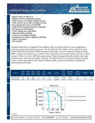
inputs, then all three cathodes (-) should be tied together and grounded as shown in Figure 3. If sinking<br />
current, then all three anodes (+) should be tied together to the +voltage as shown in Figure 4.<br />
To enable an input, apply a DC voltage source of +5VDC to +8.6VDC across the inputs. The Anodes (+)<br />
are pins 7, 9, and 11 and the Cathodes (-) are pins 8, 10, and 12.<br />
Connecting the Step Motor<br />
Phase 1 and 3 of the Step Motor is connected between pins 3 and 4 on the terminal block connector.<br />
Phase 2 and 4 of the Step Motor is connected between pins 5 and 6 on the terminal block connector.<br />
Refer to Figures 3 & 4 for TYPICAL APPLICATION HOOK-UP.<br />
NOTE: The physical direction of the motor with respect to the direction input will depend on the connection<br />
of the motor windings. To reverse the direction of the motor with respect to the direction input, swap the<br />
wires on Phase 1 and Phase 3.<br />
WARNING: Do not connect or disconnect motor wires while power is applied! This driver does not<br />
protect itself if the motor is disconnected while powered.<br />
#L010144 February 2004
12 Pin Terminal Block Description<br />
P<br />
in<br />
#<br />
Descriptio<br />
n<br />
1 G<br />
round<br />
:<br />
Return path for driver voltag e<br />
2 D C IN<br />
:<br />
Input voltage for the driver (20-80VDC)<br />
3 P<br />
hase<br />
A<br />
:<br />
Phase 1 of the Step Motor<br />
4 P<br />
hase<br />
A<br />
:<br />
Phase 3 of the Step Motor<br />
5 P<br />
hase<br />
B<br />
:<br />
Phase 2 of the Step Motor<br />
6 P<br />
hase<br />
B<br />
:<br />
Phase 4 of the Step Motor<br />
7 O N/OFF<br />
Anode<br />
(+)<br />
: This isolated input is used to enable and disable the output section of the driver.<br />
When HIGH (open) the outputs are enabled. However, this input does not inhibit the step clock.<br />
8 ON/OFF<br />
Cathode<br />
(-<br />
)<br />
9 D<br />
irection<br />
Anode (+)<br />
:<br />
This isolated input is used to change the direction of the motor. Physical direction<br />
also depends on the connection of the motor windings.<br />
10<br />
Direction<br />
Cathode<br />
(-<br />
)<br />
11<br />
1<br />
S<br />
tep<br />
Clock<br />
Input<br />
Anode<br />
(+)<br />
: A positive going edge on this isolated input advances the motor one<br />
increment. The size of the increment is dependent on the Microstep Select Inputs of Switch 1.<br />
12<br />
Step<br />
Clock<br />
Input<br />
Cathode<br />
(-<br />
)<br />
Power Supply Requirements<br />
Table 2: Pin descriptions for terminal block<br />
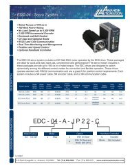
It is recommended that the <strong>MBC10101</strong> be powered by the PSA80V4A or the PSAM48V3.2A. The PSA80V4A<br />
is a 80 Volt, 4 Amp power supply that will take either 110 VAC or 220 VAC inputs and deliver 320 Watts.<br />
The PSAM48V3.2A is a 48 Volt, 3.2 Amp power supply with a universal input to accept input voltages in<br />
the range of 95 - 265VAC and deliver 150Watts.<br />
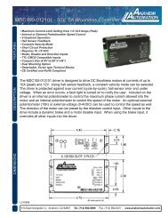
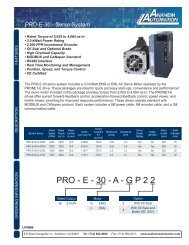
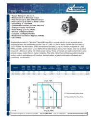
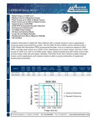
Power Supply Drawings for PSA80V4A and PSAM48V3.2A<br />
Figure 1: Dimensions for PSA80V4A<br />
Figure 2: Dimensions for PSAM48V3.2A<br />
#L010144 February 2004
Absolute Maximum Ratings<br />
Input Voltage: 80 VDC<br />
Output Current: 10.0 AMPS PEAK<br />
Max Plate Temperature: 70° C<br />
Storage Temperature: 0° to +50° C<br />
Electrical Specifications<br />
I<br />
tem<br />
Mn<br />
i<br />
Tp<br />
y<br />
M<br />
a<br />
x<br />
Unit<br />
s<br />
Setting the Output Current<br />
I nput<br />
Voltage<br />
(Power)<br />
20<br />
80<br />
80<br />
VDC<br />
P hase<br />
Output<br />
Current<br />
1.<br />
1 7 . 1 A (RMS)<br />
P hase<br />
Output<br />
Current<br />
1.<br />
5 10.<br />
0 A (PEAK)<br />
I nput<br />
Voltage<br />
(Inputs)<br />
3.<br />
5 8.<br />
6 VDC<br />
C lock<br />
Frequency<br />
0 100<br />
kHz<br />
C hopping<br />
Frequency<br />
47<br />
50<br />
53<br />
kHz<br />
O peration<br />
Temperature<br />
e 0 70<br />
C<br />
Table 3: <strong>MBC10101</strong> electrical specifications<br />
WARNING: Do not set the current setting above the step motors rated current. When using a<br />
higher current setting into a motor, the motor will overheat and burnup. Should this occur, the<br />
driver will also be damaged.<br />
The output current on the <strong>MBC10101</strong> is set by an onboard potentiometer. This potentiometer determines<br />
the per phase peak output current of the driver. The relationship between the output current and the<br />
potentiometer value is as follows:<br />
P<br />
eak<br />
Current<br />
P<br />
otentiometer<br />
Settin<br />
g<br />
P<br />
eak<br />
Curren<br />
t<br />
Potentiometer<br />
Settin<br />
g<br />
1 .5A<br />
0%<br />
7 .0A<br />
60%<br />
2 .3A<br />
10%<br />
7 .9A<br />
70%<br />
3 .1A<br />
20%<br />
8 .7A<br />
80%<br />
4 .0A<br />
30%<br />
9 .6A<br />
90%<br />
5 .0A<br />
40%<br />
10A<br />
100%<br />
6 .0A<br />
50%<br />
--<br />
--<br />
Table 4: Potentiometer values with respect to the output current<br />
Refer to Table 5 for specific motor current settings.<br />
Reducing Output Current<br />
Reducing the output current is accomplished automatically and occurs approximately 1 second after the<br />
last positive going edge of the step clock input. The amount of current per phase in the reduction mode is<br />
approximately 70% of the set current. When the current reduction circuit is activated, the current reduction<br />
resistor is paralleled with the current adjustment potentiometer. This lowers the total resistance value, and<br />
thus lowers the per phase output current.<br />
#L010144 February 2004
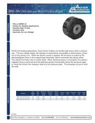
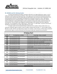
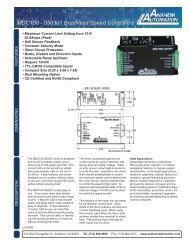
Hook Up Drawings<br />
Figure 3: Hook up for current sourcing inputs<br />
Figure 4: Hook up for current sinking inputs<br />
Dimension Drawing<br />
Figure 5: <strong>MBC10101</strong> dimensions<br />
#L010144 February 2004
Motor Selection<br />
The <strong>MBC10101</strong> is a Bipolar Microstep Driver that is compatible with both Bipolar and Unipolar Motor<br />
Configurations, (i.e. 8 and 4 lead motors, and 6 lead center tapped motors).<br />
Step motors with low current ratings and high inductance will perform better at low speeds, providing<br />
higher low-end torque. Motors with high current ratings and low inductance will perform better at higher<br />
speeds, providing more high-end torque. Higher voltages will cause the current to flow faster through the<br />
motor coils. This in turn means higher step rates can be achieved. Care should be taken not to exceed the<br />
maximum voltage of the driver.<br />
Since the <strong>MBC10101</strong> is a constant current source, it is not necessary to use a motor that is rated at the<br />
same voltage as the supply voltage. What is important is that the <strong>MBC10101</strong> is set to the appropriate<br />
current level based on the motor being used. Refer to the following chart for setting the current potentiometer<br />
based on the current code in the part number of the motor. Examples of motor part numbers are<br />
shown below. <strong>Anaheim</strong> <strong>Automation</strong> offers a comprehensive line of step motors in 14, 17, 23, 34 and 42<br />
frame sizes. Contact the factory to verify motor compatibility with the <strong>MBC10101</strong>.<br />
Step Motor Current Setting <strong>Guide</strong><br />
Motor Example<br />
Motor Current<br />
Number Code<br />
Unipolar<br />
Rating<br />
Series Peak<br />
Rating<br />
Parallel Peak<br />
Rating<br />
Series<br />
Current<br />
Setting<br />
Parallel<br />
Current<br />
Setting<br />
23D102S 02<br />
1.0A<br />
1.0A<br />
2.0A<br />
----<br />
5%<br />
23L303D-LW8<br />
03<br />
1.5A<br />
1.5A<br />
3 .0A<br />
0 %<br />
20%<br />
34N104S-LW8<br />
04<br />
2.0A<br />
2.0A<br />
4 .0A<br />
5 %<br />
30%<br />
23L4005D-LW8<br />
05<br />
2.5A<br />
2.5A<br />
5 .0A<br />
10%<br />
40%<br />
34A106B 06<br />
3.0A<br />
3.0A<br />
6 .0A<br />
20%<br />
50%<br />
34N207S-LW8<br />
07<br />
3.5A<br />
3.5A<br />
7 .0A<br />
25%<br />
60%<br />
34K108S-LW8<br />
08<br />
4.0A<br />
4.0A<br />
8 .0A<br />
30%<br />
70%<br />
42N209S-CB<br />
09<br />
4.5A<br />
4.5A<br />
9 .0A<br />
35%<br />
85%<br />
23L310S-LW8<br />
10<br />
5.0A<br />
5.0A<br />
10.0A<br />
40%<br />
100%<br />
34D311D 11<br />
5.5A<br />
5.5A<br />
11.0A<br />
45%<br />
100%<br />
42K112S-CB<br />
12<br />
6.0A<br />
6.0A<br />
12.0A<br />
50%<br />
100%<br />
34D213S 13<br />
6.5A<br />
6.5A<br />
13.0A<br />
55%<br />
100%<br />
34N314S-LW8<br />
14<br />
7.0A<br />
7.0A<br />
14.0A<br />
60%<br />
100%<br />
42N115D-CB<br />
15<br />
7.5A<br />
7.5A<br />
15.0A<br />
65%<br />
----<br />
34K416S-LW8<br />
16<br />
8.0A<br />
8.0A<br />
16.0A<br />
70%<br />
----<br />
42D119D 19<br />
9.5A<br />
9.5A<br />
19.0A<br />
90%<br />
----<br />
42N322S-CB<br />
22<br />
11.0A<br />
11.0A<br />
22.0A<br />
100%<br />
----<br />
42D225S 25<br />
12.5A<br />
12.5A<br />
25.0A<br />
100%<br />
----<br />
Table 5: Table selection for <strong>Anaheim</strong> <strong>Automation</strong> motor current settings.<br />
<strong>Anaheim</strong> <strong>Automation</strong> offers motor cable, making hook-ups quick and easy!<br />
Contact the factory or visit our website for more motor and cable offerings.<br />
#L010144 February 2004
Determining Output Current<br />
The output current for the motor used when microstepping is determined differently from that of a full/half<br />
step unipolar driver. In the <strong>MBC10101</strong>, a sine/cosine output function is used in rotating the motor. The<br />
output current for a given motor is determined by the motors current rating and the wiring configuration of<br />
the motor. There is a current adjustment potentiometer used to set the output current of the <strong>MBC10101</strong>.<br />
This sets the peak output current of the sine/cosine waves. The specified motor current (which is the<br />
unipolar value) is multiplied by a factor of 1.0, 1.4, or 2.0 depending on the motor configuration (series,<br />
half-coil, or parallel).<br />
WARNING: Do not set the current setting above the step motors rated current. When using a<br />
higher current setting into a motor, the motor will overheat and burnup. Should this occur, the<br />
driver will also be damaged.<br />
Step Motor Configurations<br />
Step motors can be configured as 4, 6, or 8 leads. Each configuration requires different currents. Refer to<br />
the lead configurations and the procedures to determine their output current.<br />
WARNING! Step motors will run hot even when configured correctly. Damage may occur to the motor if<br />
a higher than specified current is used. Most specified motor currents are maximum values. Care<br />
should be taken to not exceed these ratings.<br />
6 Lead Motors<br />
When configuring a 6 lead motor in a half-coil configuration (connected from one end of the coil to the<br />
center tap), multiply the specified per Phase (or unipolar) current rating by 1.4 to determine the current<br />
setting potentiometer value. This configuration will provide more torque at higher speeds when compared<br />
to the series configuration.<br />
When configuring the motor in a series configuration (connected from end to end with the<br />
center tap floating) use the specified per Phase (or unipolar) current rating to determine the<br />
current setting potentiometer value.<br />
#L010144 February 2004
4 Lead Motors<br />
Multiply the specified series motor current by 1.4 to determine the current adjustment potentiometer<br />
value. Four Lead Motors are usually rated with their appropriate series current, as opposed to the Phase<br />
Current, which is the rating for 6 and 8 lead motors.<br />
8 Lead Motors<br />
Series Connection: When configuring the motor windings in series, use the per Phase (or unipolar)<br />
current rating to determine the current setting potentiometer value.<br />
Parallel Connection: When configuring the motor windings in parallel, multiply the per Phase (or unipolar)<br />
current rating by 2.0 to determine the current setting potentiometer value.<br />
NOTE: After the current has been determined, according to the motor connections above, use Table 3 to<br />
choose the proper setting for the current setting potentiometer.<br />
ANAHEIM AUTOMATION, INC<br />
#L010144 February 2004