Application of Lighter-Than-Air Platforms for Power Beaming ...
Application of Lighter-Than-Air Platforms for Power Beaming ...
Application of Lighter-Than-Air Platforms for Power Beaming ...

You also want an ePaper? Increase the reach of your titles
YUMPU automatically turns print PDFs into web optimized ePapers that Google loves.
<strong>Application</strong> <strong>of</strong> <strong>Lighter</strong>-<strong>Than</strong>-<strong>Air</strong> <strong>Plat<strong>for</strong>ms</strong> <strong>for</strong><br />
<strong>Power</strong> <strong>Beaming</strong>, Generation and Communications<br />
Rajkumar Pant<br />
Department <strong>of</strong> Aerospace Engineering<br />
Indian Institute <strong>of</strong> Technology<br />
Mumbai, India<br />
Email: name@xyz.com<br />
Narayanan Komerath<br />
School <strong>of</strong> Aerospace Engineering<br />
Georgia Institute <strong>of</strong> Technology<br />
Atlanta, USA<br />
Email: komerath@gatech.edu<br />
Aravinda Kar<br />
College <strong>of</strong> Optics and Photonics<br />
University <strong>of</strong> Central Florida<br />
Orlando, USA<br />
Email: akar@creol.ucf.edu<br />
Abstract—Retail power beaming using millimeter waves <strong>of</strong>fers<br />
a rapid way to bring electric power to areas such as rural<br />
India where the terrestrial wired grid lags the demand <strong>for</strong> communications,<br />
connectivity and other services. Synergy between<br />
infrastructure development <strong>for</strong> communications and <strong>for</strong> power<br />
allows local, regional and global power exchange. This helps to<br />
bring renewable power generation devices <strong>of</strong> all scales into a<br />
seamless grid including space-based, stratospheric, low-altitude,<br />
and surface infrastructure. This paper presents a conceptual<br />
study <strong>of</strong> how lighter-than-air plat<strong>for</strong>ms (LTA) including uninhabited,<br />
remoted controlled or autonomous aerostats and airships,<br />
may be used <strong>for</strong> the above purpose. The paper highlights the<br />
synergistic application <strong>of</strong> LTA systems to the delivery <strong>of</strong> power,<br />
generation <strong>of</strong> a small amount <strong>of</strong> power, and provision <strong>of</strong> low-cost<br />
communications systems in remote areas. Significant experience<br />
has already been accumulated in using LTA systems in India<br />
<strong>for</strong> various purposes. Wind patterns drive the optimum altitude<br />
<strong>for</strong> a self-propelled LTA above 21,000 m, suitable <strong>for</strong> large<br />
stratospheric plat<strong>for</strong>ms. Altitudes above 4000 m would enable a<br />
tethered LTA to convey millimeter wave power through a waveguide<br />
integrated into the tether, tunneling through the high-loss<br />
regions <strong>of</strong> the atmosphere. The millimeter wave power beaming<br />
application requires demonstration <strong>of</strong> the projected antenna mass<br />
and other parameters. Tethered aerostats, autonomous powered<br />
airships and very high altitude plat<strong>for</strong>ms all <strong>of</strong>fer excellent<br />
opportunities. Initial sizing explorations show feasible solution<br />
spaces.<br />
Index Terms—aerostat, airship, LTA, stratospheric plat<strong>for</strong>m,<br />
optimization, millimeter wave;antenna;retail power beaming;<br />
waveguide<br />
I. BACKGROUND AND INTRODUCTION<br />
<strong>Lighter</strong>-than-<strong>Air</strong> (LTA) systems use buoyancy <strong>of</strong> a gas <strong>of</strong><br />
low molecular weight than air to come to equilibrium at a<br />
selected altitude. Hence they are able to operate even in the<br />
absence <strong>of</strong> relative motion between the plat<strong>for</strong>m and ambient<br />
air. Though LTA systems suffer from operational limitations,<br />
they have some unique capabilities, which can make them a<br />
plat<strong>for</strong>m <strong>of</strong> choice <strong>for</strong> certain applications.<br />
The most commonly known LTA plat<strong>for</strong>ms are hot-air<br />
or gas-filled balloons. Lacking effective means <strong>of</strong> steering,<br />
they are <strong>of</strong> limited use. Aerostats and airships are more<br />
capable LTA plat<strong>for</strong>ms. Aerostats are aerodynamically shaped<br />
tethered balloons mounted with fins <strong>for</strong> stability. <strong>Air</strong>ships are<br />
untethered. Onboard propulsion and control systems enable<br />
them to handle changes in ambient wind much better, and<br />
hence they can relocate and fly around.<br />
Both Aerostats and airships can act as high-altitude<br />
plat<strong>for</strong>ms <strong>for</strong> several scientific and commercial applications.<br />
They find worldwide use <strong>for</strong> long endurance aerial<br />
observation, imaging and communications, and as aerial<br />
advertisement signs. They have excellent green credentials,<br />
since their fuel consumption and power requirements are a<br />
small fraction <strong>of</strong> that <strong>of</strong> any other aerial vehicle <strong>for</strong> these<br />
applications.<br />
A. Summary <strong>of</strong> <strong>Application</strong>s<br />
Aerostats have been actively applied to various problems.<br />
These include aerial imaging [1]–[3], remote sensing [4], radar<br />
[5] visual and infrared monitoring <strong>of</strong> international borders [6],<br />
[7], airspace and movement on the ground , traffic monitoring<br />
and control [8], synthetic aperture astronomical telescopes<br />
[9]–[11], relaying electromagnetic signals [12], generation <strong>of</strong><br />
wind power [13] from the jet stream, and collection <strong>of</strong> solar<br />
power from above the cloud layer. Williams [14] proposes<br />
power generation from aerodynamic kites, but many <strong>of</strong> the<br />
application lessons may be applied and scaled up to use<br />
aerostats which can guarantee lift<strong>of</strong>f from the ground and<br />
endurance regardless <strong>of</strong> ground-level or upper-level winds.<br />
B. Relevance to Retail <strong>Power</strong> <strong>Beaming</strong><br />
When the issues in power beaming are examined, two things<br />
become clear. The first is that diffraction-limited antenna size<br />
becomes unacceptably large <strong>for</strong> rural receivers, at frequencies<br />
below 100GHz. Where low frequencies are used, antennae<br />
are sized to receive no more than the central main lobe <strong>of</strong><br />
the beam, thus losing roughly 14 % <strong>of</strong> the arriving power<br />
just through spillage. The second point is that above 10GHz,<br />
horizontal power beaming at low altitudes incurs extreme<br />
losses, and is impractical beyond 1 or 2 kilometers. For these<br />
reasons, Ref. [15] argues <strong>for</strong> adoption <strong>of</strong> the 200-225GHz band<br />
<strong>for</strong> beaming vertically through the atmosphere and a couple <strong>of</strong><br />
thousand kilometers into Space, with a lower waveband such<br />
as 100GHz <strong>for</strong> horizontal transmission over short distances.<br />
In their proposed architecture <strong>for</strong> rural power beaming in
India, local wired grids would be used within a village and its<br />
immediate surroundings. Lower-frequency wireless beaming<br />
would be used over short distances where the antenna size and<br />
transmission loss are not prohibitive, if justified by a trade<strong>of</strong>f<br />
with the immediate costs and the opportunity costs <strong>of</strong> installing<br />
a wired grid <strong>for</strong> that purpose. They argue that a wired grid will<br />
follow, dictated by the economics <strong>of</strong> power cost, once the local<br />
economy picks up using wireless power <strong>for</strong> the startup phase.<br />
To deliver power over distances <strong>of</strong> several tens <strong>of</strong> kilometers,<br />
they propose high-altitude (stratospheric) plat<strong>for</strong>ms, accompanied<br />
by lower-altitude aerostats. These enable the power<br />
to be beamed vertically up and down, minimizing distance<br />
transmitted through the moist, dense, lower troposphere, and<br />
then horizontal line-<strong>of</strong>-sight beaming through the clear, dry,<br />
low-density upper atmosphere using 220GHz beaming. Their<br />
interest stems from considering the retail power beaming end<br />
<strong>of</strong> a comprehensive Space <strong>Power</strong> Grid architecture, enabling<br />
renewable power plants around the world to exchange power<br />
through and between Space satellites [16] to reach across the<br />
planet. They have considered several <strong>of</strong> the difficult issues in<br />
millimeter wave power beaming in earlier work [17].<br />
Dessanti et al [18]have recently considered the startup phase <strong>of</strong><br />
a space solar power (SSP) using the Space <strong>Power</strong> Grid, with<br />
India and the USA as the first participating nations. While<br />
there are obviously difficult obstacles in making millimeter<br />
wave power generators and receivers <strong>for</strong> such high-power<br />
applications, and in transmitting such power efficiency, the<br />
conversation in power beaming and Space Solar <strong>Power</strong> has<br />
clearly shifted to the regime <strong>of</strong> millimeter waves. As pointed<br />
out above, LTA plat<strong>for</strong>ms at several levels provide key enablers<br />
<strong>for</strong> power beaming. The rest <strong>of</strong> this paper accordingly<br />
considers the issues in building and applying such an approach<br />
to the Indian rural electrification problem.<br />
II. PROGRAM ON AIRSHIP DESIGN AND DEVELOPMENT IN<br />
INDIA<br />
Around a decade ago, studies related to operation and<br />
design and development <strong>of</strong> airships <strong>for</strong> India were initiated<br />
at IIT Bombay through the launch <strong>of</strong> a Program on <strong>Air</strong>ship<br />
Design and Development (PADD). The principal mandate<br />
<strong>of</strong> PADD was to generate a detailed project definition<br />
report <strong>for</strong> design and development <strong>of</strong> airships to transportat<br />
goods and passengers over mountainous terrains, while<br />
operating under hot-and-high conditions. Another mandate<br />
was to establish the techno-economic feasibility <strong>for</strong> leasing<br />
some airships and gaining operational experience in India [19].<br />
As part <strong>of</strong> this project, the baseline specifications <strong>of</strong> a<br />
Demo <strong>Air</strong>ship (with payload capacity <strong>of</strong> 100 kg) and a<br />
PaxCargo <strong>Air</strong>ship (with payload capacity <strong>of</strong> 1500 kg) <strong>for</strong><br />
operation at an altitude <strong>of</strong> 3500 m AMSL under ISA+15<br />
deg. conditions were obtained through conceptual design<br />
and sizing studies. These studies involved development <strong>of</strong> a<br />
methodology <strong>for</strong> initial sizing and sensitivity analysis [20],<br />
estimation <strong>of</strong> stresses on the envelope material, estimation<br />
<strong>of</strong> aerodynamic, stability and control characteristics, and<br />
dynamic modeling <strong>of</strong> these airships. Through these studies,<br />
the key sizing parameters and their sensitivities to the payload<br />
available and/or the envelope size were established, and<br />
critical design features, work packages and major tasks<br />
were identified. Some design features that could greatly<br />
enhance the operational capability and safety <strong>of</strong> airships over<br />
mountainous terrain were also identified and studied.<br />
After completion <strong>of</strong> this study, an LTA Systems laboratory<br />
was set-up at IIT Bombay, where many subsequent studies and<br />
projects were carried out to further the design and development<br />
<strong>of</strong> LTA systems <strong>for</strong> various applications in India. These studies<br />
include design development and field prototype testing <strong>of</strong><br />
indoor remotely controlled airships <strong>for</strong> neural network control<br />
hardware implementation [20], aerostats as plat<strong>for</strong>ms <strong>for</strong> lowcost<br />
re-locatable wireless communications systems [21], [22],<br />
outdoor remotely controlled airships <strong>for</strong> product promotion<br />
[1], aerial river ferry using superheated steam-filled balloons<br />
[23], and aerostats <strong>for</strong> snow cover evaluation [24].<br />
III. AEROSTATS FOR LAST MILE WIRELESS<br />
COMMUNICATIONS<br />
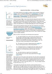
Figure 1 is a conceptual sketch <strong>of</strong> a low-cost re-locatable<br />
wireless communications system, from [21], in which a<br />
fixed tower is replaced by a tethered aerostat on which a<br />
communications antenna is mounted. Such a system can bring<br />
the rural areas in India into the mainstream by providing<br />
them last mile connectivity, especially when other modes <strong>of</strong><br />
communications are severely hampered.<br />
The technical feasibility <strong>of</strong> this system <strong>for</strong> voice and data<br />
communication over a radius <strong>of</strong> 7.5 km was established by the<br />
design, fabrication and field trials <strong>of</strong> two working prototypes<br />
[21]. A recent study [22] concluded that the total cost <strong>of</strong> this<br />
innovative solution <strong>for</strong> providing internet access to rural areas<br />
is nearly half <strong>of</strong> the tower based system, over a life cycle <strong>of</strong><br />
three years. An additional advantage <strong>of</strong> this system is that it<br />
is easily be re-furbished and re-located, which makes it more<br />
adaptable to changes in technology and needs.<br />
IV. SIZING OF PROTOTYPE AND FULL-SCALE AIRSHIP<br />
FOR POWER GENERATION<br />
The concept <strong>of</strong> stratospheric airships is still quite novel,<br />
and no such system is currently under actual deployment<br />
anywhere in the globe. Several authors have considered such<br />
systems. Brown [25] considered such plat<strong>for</strong>ms as part <strong>of</strong> his<br />
exploration <strong>of</strong> options <strong>for</strong> wireless beaming. Djuknic [26]<br />
cited wind velocity pr<strong>of</strong>ile data acquired and transmitted by<br />
the US National Aeronautics and Space Administration High<br />
Resolution Doppler Imager (HRDI) using a high-altitude<br />
plat<strong>for</strong>m. Rehmet et al. [27] provided sizing methodology<br />
<strong>for</strong> high altitude plat<strong>for</strong>ms. Thornton et al [28] described the<br />
European HeliNet program to use high-altitude plat<strong>for</strong>ms in<br />
wireless broadband communications.
TABLE I<br />
OPERATING REQUIREMENTS OF AIRSHIP FOR POWER GENERATION<br />
Parameter Units Value<br />
Floating Altitude km 20<br />
Mission Speed m/s 25<br />
Envelope Slenderness ratio [Length/Diameter] N/A 7.64<br />
Off standard Temperature degrees C ISA+20<br />
Discharging time hours 8<br />
Average Irradiance W/m 2 213.76<br />
Solar Cell Efficiency % 20<br />
Energy Density <strong>of</strong> Regenerative Fuel Cells W.h/kg 429<br />
TABLE II<br />
KEY PARAMETERS AND MASS BREAKDOWN FOR PROTOTYPE AND FULL<br />
SCALE AIRSHIP<br />
Fig. 1. Aerostat based wireless communications system. From [21]<br />
Tozer and Grace [29] considered such plat<strong>for</strong>ms <strong>for</strong><br />
wireless communications. They cited commercial high<br />
altitude plat<strong>for</strong>m programs, and the PWI tethered aerostat<br />
program in Brazil as examples <strong>of</strong> contemporary programs<br />
(in 2001). Advances in solar-powered airplanes such as the<br />
NASA Solar Pathfinder, and in the area <strong>of</strong> solar-augmented<br />
ship power, indicate growing interest in solutions that will<br />
enable substantial solar power generation from high-altitude<br />
plat<strong>for</strong>ms that are immune to clouds and rain. On-station<br />
endurance as long as 5 years is being advertised by<br />
developers. The reliability <strong>of</strong> wireless links may not live<br />
up to the 99.99 % availability criterion, however, unlike<br />
spacecraft, these plat<strong>for</strong>ms can be brought to the ground<br />
<strong>for</strong> repair and maintenance. They cite energy storage as a<br />
likely issue. Antonini [30] describe stratospheric relays <strong>for</strong><br />
communications from and to satellites. They consider two<br />
HAP-satellite integrated concept <strong>for</strong> both radio and optical<br />
links. One <strong>of</strong> the advantages cited is in helping to augment<br />
the terrestrial telephone infrastructure.<br />
For the power-beaming application, it will be necessary<br />
to first create a model-scale prototype airship to prove the<br />
concept, and then to develop a full scale version <strong>of</strong> the same.<br />
The airship to be used <strong>for</strong> power generation purposes would<br />
be positioned in stratosphere, in an altitude band <strong>of</strong> 17-21<br />
km AMSL, in which the ambient wind direction undergoes an<br />
inversion and thus a zero-gradient region, thus reducing the<br />
onboard power required <strong>for</strong> station-keeping. A methodology<br />
<strong>for</strong> sizing <strong>of</strong> an airship <strong>of</strong> ellipsoid envelope shape given the<br />
set <strong>of</strong> operating requirements was developed by Gawale and<br />
Pant [31], based on the general scheme suggested by Rehmet<br />
et al [27]. Sizing <strong>of</strong> an airship was carried out <strong>for</strong> the operating<br />
requirements specified in Table I.<br />
As mentioned by Tozer [29], not all the parameters scale<br />
linearly, and hence it will be necessary to build some full-scale<br />
prototypes to understand all the issues <strong>of</strong> full-scale operations.<br />
Parameter Units Prototype Full Scale %change<br />
Envelope Volume m 3 38939 97538 150<br />
Envelope Area m 2 8822 16271 84<br />
Envelope Length m 161 219 36<br />
Envelope Diameter m 21 29 36<br />
Net Disposable Lift kg 2920 7316 150<br />
Surface <strong>for</strong> Solar Cells m2 1417 2495 76<br />
Thrust Required N 1093 1924 76<br />
<strong>Power</strong> Required kW 28 73 158<br />
Propulsion mass kg 633 1128 78<br />
Structure Mass kg 2237 4187 87<br />
Take Off Empty Mass kg 2870 5316 85<br />
It is assumed that the prototype airship would be required to<br />
hover at an altitude <strong>of</strong> 20 km AMSL and beam a small amount<br />
<strong>of</strong> power to a ground based receiver. Assuming an antenna <strong>of</strong><br />
25 m diameter weighing 0.1 per m 2 , and approximately 20<br />
kg weight <strong>of</strong> other on-board equipment, the required payload<br />
capacity is approximately 50 kg. It is also assumed that a<br />
solar regenerative fuel cell system would be installed on the<br />
airship to meet its own power requirements, and an excess<br />
capacity <strong>of</strong> 1 kW. For the full scale system however, an<br />
antenna <strong>of</strong> 150 m diameter and 225 kg weight <strong>of</strong> other onboard<br />
equipment and excess power generation capability <strong>of</strong> 25<br />
kW is assumed. The last four parameters listed in Table 1 are<br />
related to solar power system; the values <strong>of</strong> these parameters<br />
are appropriate <strong>for</strong> operating conditions in India, which are<br />
quoted in [32]. Table II lists the key output parameters and<br />
the mass breakdown <strong>for</strong> the two airships, with Hydrogen as the<br />
LTA gas. It can be seen that the percentage change in airship<br />
dimensions, power required, and component weights is much<br />
smaller in proportion to the change in payload and excess<br />
power generation capability <strong>of</strong> the airship, which illustrates<br />
the fact that airships become much more efficient as their<br />
size is increased. On the issue <strong>of</strong> whether ground antenna<br />
need be steerable, Tozer [29] points out that if the circular<br />
position error due to airship drift is less than the antenna<br />
beamwidth, steerable antennae may not be necessary, and<br />
communications could be maintained by increasing gain. This<br />
is not an acceptable solution <strong>for</strong> power beaming as it will entail<br />
large losses. Whether the right solution is to require every<br />
receiving antenna on the ground to be steerable, or to build<br />
some pointing capability into the plat<strong>for</strong>m, must be considered
TABLE III<br />
OPERATING REQUIREMENTS OF AN AEROSTAT FOR POWER BEAMING<br />
Fig. 2.<br />
Sensitivity <strong>of</strong> envelope volume to ambient wind speeds<br />
Parameter Units Value<br />
Onboard payload mass kg 200<br />
Floating Altitude km 5<br />
Ambient wind Speed m/s 15<br />
Envelope Slenderness ratio [Length/Diameter] NA 3.05<br />
Off standard Temperature degrees ISA+20<br />
Diurnal temperature variation degrees +/- 10<br />
Time on station be<strong>for</strong>e envelope top-up months 4<br />
Envelope material specific mass kg/m2 0.21<br />
Helium leakage rate lit/ m 2 / day 2.5<br />
Tether specific Mass kg/m 0.25<br />
TABLE IV<br />
KEY PARAMETERS AND MASS BREAKDOWN OF AN AEROSTAT FOR POWER<br />
BEAMING<br />
Fig. 3.<br />
Sensitivity <strong>of</strong> envelope volume to operating altitude<br />
Parameter Units Value<br />
Envelope Volume m 3 4111<br />
Envelope Surface Area m 2 1413<br />
Envelope Length m 43<br />
Envelope Diameter m 14<br />
Net Disposable Lift kg 2596<br />
Tether length m 5500<br />
Envelope group Mass kg 353<br />
Elastic Strip mass kg 98<br />
Fin Assembly Mass kg 141<br />
Tether Mass kg 1545<br />
Gross Take Off Empty Mass kg 2137<br />
in detail later as part <strong>of</strong> the architecture design.<br />
V. SENSITIVITY ANALYSES<br />
Sensitivity analyses were carried out to understand the<br />
interdependency <strong>of</strong> key design parameters and to identify<br />
the design drivers i.e., the parameters to which the airship<br />
per<strong>for</strong>mance at the required operating conditions is most<br />
sensitive. Figure 2 illustrates the exponential increase in the<br />
envelope volume with increase in ambient wind speed that<br />
the airship is expected to handle. The increase in size <strong>of</strong> the<br />
envelope if Helium is used instead <strong>of</strong> Hydrogen is also quite<br />
apparent.<br />
Figure 3 illustrates the sensitivity <strong>of</strong> envelope volume to the<br />
operating altitude. It can be seen that the optimum operating<br />
altitude in India is around 21km AMSL. The envelope volume<br />
is larger at lower altitudes than this due to higher ambient wind<br />
velocities, which increase the powerplant size and weight.<br />
Envelope volume is also larger at higher altitude than this,<br />
due to loss in buoyancy <strong>of</strong> the LTA gas.<br />
VI. SIZING OF AN AEROSTAT FOR POWER BEAMING<br />
It is not enough to generate the power using a stratospheric<br />
airship; it is also required to beam this power down to the<br />
ground. A tethered aerostat deployed at an altitude <strong>of</strong> 5<br />
km AMSL could be used <strong>for</strong> this purpose; this operating<br />
height will ensure that the size and weight <strong>of</strong> the onboard<br />
equipment needed <strong>for</strong> this purpose will be quite manageable.<br />
The aerostat altitude may be brought down to 4 km to 5<br />
km with tethered aerostats. The mass per unit length <strong>of</strong> the<br />
tether would probably dictate the optimum altitude in this case.<br />
A methodology <strong>for</strong> sizing <strong>of</strong> a tethered aerostat system<br />
<strong>for</strong> high altitude applications has been developed by Raina<br />
et al. [24]. Using this methodology, an aerostat system was<br />
sized <strong>for</strong> the operating requirements listed in Table III. The<br />
aerostat envelope was assumed to be <strong>of</strong> GNVR pr<strong>of</strong>ile with<br />
three inflatable fins in inverter Y layout. It was assumed that<br />
a total on-board payload carrying capacity <strong>of</strong> 200 kg would<br />
suffice to meet the weight <strong>of</strong> the power beaming equipment. It<br />
was also assumed that the aerostat would be required to stay<br />
afloat <strong>for</strong> a continuous deployment period <strong>of</strong> 4 months in a<br />
year be<strong>for</strong>e the need to top up the gas that would have leaked<br />
out from the envelope.<br />
VII. MILLIMETER WAVEGUIDE REQUIREMENTS AND<br />
SIZING<br />
Given that modern tethers have diameter well over 25<br />
mm and already convey small amounts <strong>of</strong> electrical power<br />
and communication signals, one could consider whether a<br />
tether could be made, that incorporates a waveguide <strong>for</strong><br />
Megawatt-level transmission <strong>of</strong> millimeter wave power.
Below we consider some sizing numbers when using<br />
waveguides to transfer power between aerostats and ground<br />
stations. For 220 GHz frequency, the wavelength is 1.36<br />
mm. A waveguide <strong>of</strong> length/breadth ratio 2 is assumed. The<br />
length ’a’ <strong>of</strong> the rectangular hollow waveguide cross-section<br />
corresponding to half the wavelength is then 0.68 mm, and<br />
the breadth 0.34 mm. The wall thickness is assumed to be 2<br />
% <strong>of</strong> the half-breadth, which becomes 34 microns <strong>for</strong> each<br />
waveguide duct. These parameters give a wall mass <strong>of</strong> 0.5<br />
grams per meter <strong>of</strong> waveguide length. The maximum power<br />
that can be transmitted per waveguide without risking air<br />
breakdown [33], can be derived <strong>for</strong> this case to be 4.835<br />
kW. With a safety factor <strong>of</strong> 2, transmission is limited to 2.42<br />
kW. Higher power density and hence lower system mass<br />
may be achieved by using rare gases or vacuum rather than<br />
low-density, dry air as the waveguide medium. This and<br />
other refinements are left to detailed design. Above, we have<br />
assumed 1-atmosphere air as the medium in calculating the<br />
breakdown power level. By evacuating the waveguide down<br />
to a very low pressure, the breakdown power level could<br />
be substantially increased, however the waveguide mass and<br />
operational complexity may increase due to the evacuation<br />
requirement.<br />
If each aerostat is to handle 5 MW <strong>of</strong> power, and be<br />
tied with 4 tethers, then each tether must have a bundle <strong>of</strong><br />
roughly 517 waveguides. These will occupy a cross-section<br />
area with an effective diameter <strong>of</strong> roughly 25.2 millimeters,<br />
not inconsistent with the diameter <strong>of</strong> present-day tethers [34].<br />
We see that aerostats must be spaced no more than 13.35km<br />
apart. We will assume nominally that they are spaced 10 km<br />
apart. This implies that if each were to deliver 5MW, we<br />
could bring essential electric power to a set <strong>of</strong> perhaps 10<br />
villages. At first sight these numbers look reasonable <strong>for</strong> a<br />
region which has never enjoyed access to the electric power<br />
grid.<br />
The waveguide metal mass in the tether is then 0.281<br />
kg per meter <strong>of</strong> tether, compared to the present day tether<br />
technology <strong>of</strong> roughly 0.3 kg per tether. If the average tether<br />
length is 6000 m in order to allow an aerostat altitude above<br />
ground level <strong>of</strong> 5000 meters, then the waveguide mass in each<br />
tether is nearly 1700 kg. How these waveguides are to be<br />
incorporated into tethers is again a matter <strong>for</strong> detailed design.<br />
The wordwide market <strong>for</strong> tethered power exchange aerostats<br />
may become large enough that waveguide-integrated tethers<br />
may become mass-produced commodities. The waveguides<br />
themselves can certainly carry some tension, being made<br />
<strong>of</strong> steel. Whether they can support their own weight, and<br />
provide extra tensile strength, remains to be calculated.<br />
Requirements <strong>for</strong> waveguides can be developed from<br />
the above considerations. Since the beam path in this case<br />
is straight, one absolute upper bound on attenuation is<br />
the attenuation <strong>of</strong> moist air. There is no point in having<br />
a waveguide to a tethered aerostat, that achieves less<br />
transmission than what a beam through moist air would<br />
achieve. A receiving antenna on the aerostat can be designed<br />
<strong>for</strong> substantially less weight penalty than a waveguide through<br />
a tether. An evacuated tube waveguide should be able to<br />
achieve nearly the propagation effectiveness <strong>of</strong> the dry upper<br />
atmosphere, but the wall thickness required to support 1<br />
atmosphere <strong>of</strong> pressure difference may pose a large weight<br />
penalty. A better alternative may be to fill the waveguide with<br />
a suitable dry gas that transmits the specific chosen frequency<br />
well. These issues and opportunities remain to be investigated.<br />
The possibility <strong>of</strong> sending power with minimal losses<br />
through tethers opens the way to an aerostat-based rural<br />
beamed power architecture and addresses some <strong>of</strong> the difficulties<br />
identified in Komerath et al [15]. The waveguide<br />
enables efficient transmission at 220 GHz vertically through<br />
moist, dense atmospheric conditions, thus greatly reducing<br />
the weather objection to millimeter wave architectures. In<br />
addition, the horizontal transmission loss per kilometer is very<br />
low above 4000 m, so that there is no need to go down to<br />
100 GHz <strong>for</strong> this purpose. The entire architecture can then be<br />
focused on 220 GHz. By 220 GHz, we imply that the best<br />
choice <strong>of</strong> wavelength around this window will be chosen in<br />
detailed design. The antennae and transmitters can then be<br />
designed to optimize efficiency <strong>for</strong> just the one wavelength,<br />
enabling resonant architectures with very high efficiency.<br />
VIII. CONCLUSIONS<br />
An initial study has been conducted on the parameter<br />
values needed to design lighter than air plat<strong>for</strong>ms to transfer<br />
millimeter wave beamed power between ground stations. Both<br />
tethered and self-powered airships have been considered. The<br />
initial estimates <strong>of</strong> the size and mass <strong>of</strong> tethered aerostats<br />
are well within the parameter range <strong>of</strong> present concepts or<br />
operating plat<strong>for</strong>ms. An operating altitude <strong>of</strong> more than 4000<br />
m above mean sea level enables going well above the moist<br />
and dense parts <strong>of</strong> the atmosphere, and above the monsoon<br />
cloud layer in India. This permits efficient millimeter wave<br />
beaming between aerostats, and stationing these aerostats at<br />
substantial distances to serve the rural market.<br />
The possibility <strong>of</strong> incorporating an evacuated waveguide<br />
into the tether <strong>of</strong> an aerostat has been considered. The<br />
geometric size becomes small enough to fit within modern<br />
tether cross-section envelopes. With 4 tethers <strong>of</strong> no more than<br />
present tether size, 5 MW could be transmitted to or from<br />
an aerostat using waveguide bundles inside each <strong>of</strong> 4 tethers,<br />
even assuming air-filled rather than evacuated tethers.<br />
Thus to a first approximation we see that the conceptual design<br />
<strong>for</strong> synergistic power beaming and communications using<br />
aerostats, is viable. Substantial challenges remain in achieving<br />
the projected parameters <strong>for</strong> the design <strong>of</strong> the antenna system,<br />
and in pointing and station-keeping to sufficient accuracy. The<br />
attitude control and shaping <strong>of</strong> the aerostats to optimize the<br />
design, taking into account wind <strong>for</strong>ces and antenna shape
equirements, remains as one <strong>of</strong> the important issues to be<br />
considered. The issue <strong>of</strong> heating due to the large amount<br />
<strong>of</strong> power being transacted, as well as the opportunities <strong>for</strong><br />
gathering solar power using the same aerostats and the proper<br />
use <strong>for</strong> such power, also remain to be considered. However,<br />
the paper shows that aerostats can play a viable and vital role<br />
in a beamed power architecture.<br />
ACKNOWLEDGMENT<br />
Participation in this conference is enabled by the NASA<br />
EXTROVERT initiative to develop resources <strong>for</strong> crossdisciplinary<br />
innovation. Mr. Tony Springer is the technical<br />
monitor.<br />
REFERENCES<br />
[1] A. Gawale, A. A. Raina, R. S. Pant, and Y. P. Jahagirdar, “Design<br />
fabrication and operation <strong>of</strong> low cost remotely controlled airships in<br />
india,” in Proceedings <strong>of</strong> AIAA’s 8th Aviation Technology Integration<br />
and Operations (ATIO) Conference, no. AIAA-2008-8853, Anchorage,<br />
Alaska, September 2008.<br />
[2] A. Kanoria, “Comparison <strong>of</strong> blowby characteristics <strong>of</strong> conventional and<br />
winged aerostats,” Communications in Aerospace Systems Design and<br />
Engineering, vol. 1, no. 1, 2010.<br />
[3] A. Raina, A. Gawale, and R. Pant, “Design, fabrication and field testing<br />
<strong>of</strong> aerostat system,” in National Seminar on Strategic <strong>Application</strong>s<br />
<strong>of</strong> <strong>Lighter</strong>-<strong>Than</strong>-<strong>Air</strong> (LTA) Vehicles at Higher Altitudes, Snow and<br />
Avalanche Study Establishment, Manali, India, 2007, pp. 12–13.<br />
[4] L. Vierling, M. Fersdahl, X. Chen, Z. Li, and P. Zimmerman, “The<br />
short wave aerostat-mounted imager (swami): A novel plat<strong>for</strong>m <strong>for</strong><br />
acquiring remotely sensed data from a tethered balloon,” Remote sensing<br />
<strong>of</strong> environment, vol. 103, no. 3, pp. 255–264, 2006.<br />
[5] C. Chang-sheng and Z. Pan-feng, “Analysis <strong>of</strong> tethered aerostat borne<br />
radar system,” Radar Science and Technology, vol. 6, 2007.<br />
[6] A. Rajani, R. Pant, and K. Sudhakar, “Dynamic stability analysis <strong>of</strong> a<br />
tethered aerostat,” Journal <strong>of</strong> aircraft, vol. 47, no. 5, pp. 1531–1538,<br />
2010.<br />
[7] C. Ram and R. Pant, “Multidisciplinary shape optimization <strong>of</strong> aerostat<br />
envelopes,” Journal <strong>of</strong> aircraft, vol. 47, no. 3, pp. 1073–1076, 2010.<br />
[8] S. Peterson, “The small aerostat system: Field tested, highly mobile<br />
and adaptable,” in AIAA 5th Aviation, Technology, Integration, and<br />
Operations Conference (ATIO), Arlington, Virginia, no. AIAA Paper<br />
2005-7444, September 2005.<br />
[9] F. Deschenes and M. Nahon, “Design improvements <strong>for</strong> a multitethered<br />
aerostat system,” in 2005 AIAA Atmospheric Flight Mechanics<br />
Conference and Exhibit; San Francisco, CA. American Institute <strong>of</strong><br />
Aeronautics and Astronautics, 1801 Alexander Bell Drive, Suite 500,<br />
Reston, VA, 20191-4344, USA,, 2005, pp. 1–12.<br />
[10] C. Lambert, A. Saunders, C. Craw<strong>for</strong>d, and M. Nahon, “Design <strong>of</strong> a<br />
one-third scale multi-tethered aerostat system <strong>for</strong> precise positioning <strong>of</strong><br />
a radio telescope receiver,” in CASI Flight Mechanics and Operations<br />
Symposium, 2003.<br />
[11] J. Fitzsimmons, B. Veidt, and P. Dewdney, “Steady-state analysis <strong>of</strong><br />
the multi-tethered aerostat plat<strong>for</strong>m <strong>for</strong> the large adaptive reflector<br />
telescope,” in Proceedings <strong>of</strong> SPIE, vol. 4015, 2000, p. 476.<br />
[12] S. Relekar and R. Pant, “<strong>Air</strong>ships as a low cost alternative to communication<br />
satellites,” in National Conference on LTA Technologies. Agra:<br />
Aerial Delivery Research and Development Establishment, October<br />
2002.<br />
[13] B. Lansdorp and P. Williams, “The laddermill-innovative wind energy<br />
from high altitudes in holland and australia,” in Wind <strong>Power</strong>, 2006.<br />
[14] P. Williams, B. Lansdorp, and W. Ockels, “Optimal crosswind towing<br />
and power generation with tethered kites,” Journal <strong>of</strong> Guidance Control<br />
and Dynamics, vol. 31, no. 1, pp. 81–93, 2008.<br />
[15] N. Komerath and G. Chowdhary, “Retail beamed power <strong>for</strong> a micro<br />
renewable energy architecture: Survey,” Proceedings <strong>of</strong> the ISED 2010<br />
Conference, Bhubhaneshwar, India, December 2010.<br />
[16] N. Komerath and P. Komerath, “Implications <strong>of</strong> inter-satellite power<br />
beaming using a space power grid,” in IEEE Aerospace Conference, no.<br />
Paper P1696, Big Sky, MT, March 2011.<br />
[17] N. Komerath, V. Venkat, and J. Fernandez, “Near millimeter wave issues<br />
<strong>for</strong> a space power grid,” in Proceedings <strong>of</strong> IASSPES2009, Huntsville,<br />
AL, USA, March 2009.<br />
[18] B. Dessanti, N. Picon, C. Rios, S. Shah, and N. Komerath, “A US-India<br />
power exchange towards a space power grid,” in Proceedings <strong>of</strong> ISDC<br />
2011. Huntsville, AL, USA: National Space Society, May 2011.<br />
[19] R. Pant, “Program on airship design and development,” Website<br />
<strong>of</strong> the Indian Institute <strong>of</strong> Technology, Mumbai. [Online]. Available:<br />
http://www.aero.iitb.ac.in/ ∼ airships<br />
[20] R. Sangole, S. Agashe, K. Palshikar, and G. Nakanekar, “Design, fabrication<br />
and testing <strong>of</strong> remotely controlled indoor airship employed <strong>for</strong><br />
neural networks hardware experimentation,” Master’s thesis, Mechanical<br />
Engineering Department, PVG College <strong>of</strong> Engineering, University <strong>of</strong><br />
Pune, India, 2006.<br />
[21] V. Gawande, R. A. A., P. Bilaye, R. S. Pant, and U. B. Desai, “Design<br />
and fabrication <strong>of</strong> an aerostat <strong>for</strong> wireless communication in remote<br />
areas,” in Proceedings <strong>of</strong> AIAA’s 7th Aviation, Technology, Integration,<br />
and Operations (ATIO) Conference and 17th <strong>Lighter</strong>-<strong>Than</strong>-<strong>Air</strong> Systems<br />
Technology Conference, no. AIAA-2007-7832, Belfast, Northern Ireland,<br />
UK, September 2007.<br />
[22] P. Bilaye, V. Gawande, U. Desai, A. Raina, and R. Pant, “Low cost<br />
wireless internet access <strong>for</strong> rural areas using tethered aerostats,” in<br />
Industrial and In<strong>for</strong>mation Systems, 2008. ICIIS 2008. IEEE Region<br />
10 and the Third international Conference on. IEEE, 2008, pp. 1–5.<br />
[23] S. Banerjee, A. Raina, and R. Pant, “Low cost trans-river aerial-ferry<br />
using a novel lta system,” in Proceedings <strong>of</strong> the 8th Aviation Technology<br />
Integration and Operations (ATIO) Conference, Anchorage, Alaska, no.<br />
AIAA-2008-8851. American Institute <strong>of</strong> Aeronautics and Astronautics,<br />
2008.<br />
[24] A. Raina, K. M. Bhandari, and R. S. Pant, “Conceptual design <strong>of</strong> a<br />
high altitude aerostat <strong>for</strong> study <strong>of</strong> snow pattern,” in Proceedings <strong>of</strong><br />
International Symposium on Snow and Avalanches (ISSA-09). Manali,<br />
India: SASE, April 2009.<br />
[25] W. Brown, “The history <strong>of</strong> power transmission by radio waves,” Microwave<br />
Theory and Techniques, IEEE Transactions on, vol. 32, no. 9,<br />
pp. 1230–1242, 1984.<br />
[26] G. Djuknic, J. Freidenfelds, and Y. Okunev, “Establishing wireless<br />
communications services via high-altitude aeronautical plat<strong>for</strong>ms: a<br />
concept whose time has come” Communications Magazine, IEEE,<br />
vol. 35, no. 9, pp. 128–135, 1997.<br />
[27] M. A. Rehmet, H. Kroplin, B., F. Epperlein, R. Kornmann, and R. Schubert,<br />
“Recent developments on high altitude plat<strong>for</strong>ms,” in Proceedings<br />
<strong>of</strong> the 3rd International <strong>Air</strong>ship Convention and Exhibition, no. Paper<br />
B-8, Friedrichshafen, Germany, July 2000.<br />
[28] J. Thornton, D. Grace, C. Spillard, T. Konefal, and T. Tozer, “Broadband<br />
communications from a high-altitude plat<strong>for</strong>m: the european helinet programme,”<br />
Electronics & Communication Engineering Journal, vol. 13,<br />
no. 3, pp. 138–144, 2001.<br />
[29] T. Tozer and D. Grace, “High-altitude plat<strong>for</strong>ms <strong>for</strong> wireless communications,”<br />
Electronics & Communication Engineering Journal, vol. 13,<br />
no. 3, pp. 127–137, 2001.<br />
[30] M. Antonini, E. Cianca, A. De Luise, M. Pratesi, and M. Ruggieri,<br />
“Stratospheric relay: potentialities <strong>of</strong> new satellite-high altitude plat<strong>for</strong>ms<br />
integrated scenarios,” in Aerospace Conference, 2003. Proceedings.<br />
2003 IEEE, vol. 3. IEEE, 2003, pp. 3 1211–3 1219.<br />
[31] A. Gawale and R. Pant, “A methodology <strong>for</strong> initial sizing and sensitivity<br />
analyses <strong>of</strong> stratospheric airship as a plat<strong>for</strong>m <strong>for</strong> pseudolite based<br />
precision navigation system,” in Proceedings <strong>of</strong> 16th <strong>Lighter</strong>-than-<strong>Air</strong><br />
and Balloon Systems Conference AIAA Conference, no. AIAA 2005-<br />
7489, Arlington, Virginia, USA, September 2005.<br />
[32] A. P. Tyagi, “Solar radiant energy in india,” MNRE Monograph, Pune,<br />
IMD,, 2009.<br />
[33] Y. Baeyens, “<strong>Power</strong> capacity <strong>of</strong> waveguides,” in E4318-Microwave<br />
Circuit Design Course Notes, no. Lecture 4. Columbia University,<br />
Spring 2005.<br />
[34] anon. (2011) What is a tether [Online]. Available: http://www.ticomlp.<br />
com
![p density of fluid, kg/m3 [Greek letter rho] V mean velocity of fluid, m ...](https://img.yumpu.com/50595898/1/184x260/p-density-of-fluid-kg-m3-greek-letter-rho-v-mean-velocity-of-fluid-m-.jpg?quality=85)