Subsonic Airflow Effects - Airfoils and Wings
Subsonic Airflow Effects - Airfoils and Wings
Subsonic Airflow Effects - Airfoils and Wings

You also want an ePaper? Increase the reach of your titles
YUMPU automatically turns print PDFs into web optimized ePapers that Google loves.
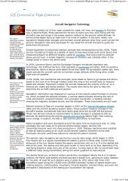
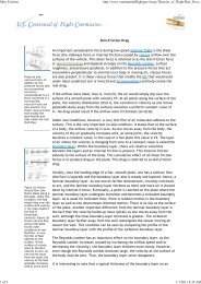
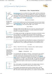
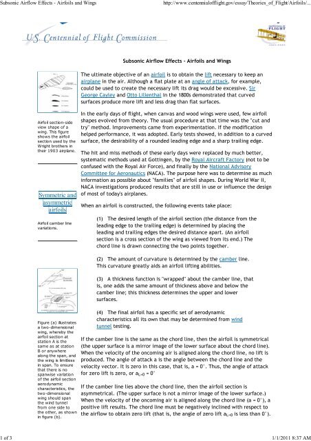
<strong>Subsonic</strong> <strong>Airflow</strong> <strong>Effects</strong> - <strong>Airfoils</strong> <strong>and</strong> <strong>Wings</strong>http://www.centennialofflight.gov/essay/Theories_of_Flight/<strong>Airfoils</strong>/...1 of 3 1/1/2011 8:37 AM<strong>Subsonic</strong> <strong>Airflow</strong> <strong>Effects</strong> - <strong>Airfoils</strong> <strong>and</strong> <strong>Wings</strong>The ultimate objective of an airfoil is to obtain the lift necessary to keep anairplane in the air. Although a flat plate at an angle of attack, for example,could be used to create the necessary lift its drag would be excessive. SirGeorge Cayley <strong>and</strong> Otto Lilienthal in the 1800s demonstrated that curvedsurfaces produce more lift <strong>and</strong> less drag than flat surfaces.Airfoil section-sideview shape of awing. This figureshows the airfoilsection used by theWright brothers intheir 1903 airplane.Symmetric <strong>and</strong>asymmetricairfoilsAirfoil camber linevariations.In the early days of flight, when canvas <strong>and</strong> wood wings were used, few airfoilshapes evolved from theory. The usual procedure at that time was the "cut <strong>and</strong>try" method. Improvements came from experimentation. If the modificationhelped performance, it was adopted. Early tests showed, in addition to a curvedsurface, the desirability of a rounded leading edge <strong>and</strong> a sharp trailing edge.The hit <strong>and</strong> miss methods of these early days were replaced by much better,systematic methods used at Gottingen, by the Royal Aircraft Factory (not to beconfused with the Royal Air Force), <strong>and</strong> finally by the National AdvisoryCommittee for Aeronautics (NACA). The purpose here was to determine as muchinformation as possible about "families" of airfoil shapes. During World War II,NACA investigations produced results that are still in use or influence the designof most of today's airplanes.When an airfoil is constructed, the following events take place:(1) The desired length of the airfoil section (the distance from theleading edge to the trailing edge) is determined by placing theleading <strong>and</strong> trailing edges the desired distance apart. (An airfoilsection is a cross section of the wing as viewed from its end.) Thechord line is drawn connecting the two points together.(2) The amount of curvature is determined by the camber line.This curvature greatly aids an airfoil lifting abilities.(3) A thickness function is "wrapped" about the camber line, thatis, one adds the same amount of thickness above <strong>and</strong> below thecamber line; this thickness determines the upper <strong>and</strong> lowersurfaces.Figure (a) illustratesa two-dimensionalwing, whereby theairfoil section atstation A is thesame as at stationB or anywherealong the span, <strong>and</strong>the wing is limitlessin span. To ensurethat there is nospanwise variationof the airfoil sectionaerodynamiccharacteristics, thetwo-dimensionalwing should spanthe wind tunnelfrom one side tothe other, as shownin figure (b).(4) The final airfoil has a specific set of aerodynamiccharacteristics all its own that may be determined from windtunnel testing.If the camber line is the same as the chord line, then the airfoil is symmetrical(the upper surface is a mirror image of the lower surface about the chord line).When the velocity of the oncoming air is aligned along the chord line, no lift isproduced. The angle of attack a is the angle between the chord line <strong>and</strong> thevelocity vector. It is zero in this case, that is, a = 0°. Thus, the angle of attackfor zero lift is zero, or a L=0 = 0°If the camber line lies above the chord line, then the airfoil section isasymmetrical. (The upper surface is not a mirror image of the lower surface.)When the velocity of the oncoming air is aligned along the chord line (a = 0°), apositive lift results. The chord line must be negatively inclined with respect tothe airflow to obtain zero lift (that is, the angle of zero lift a L=0 is less than 0°).
<strong>Subsonic</strong> <strong>Airflow</strong> <strong>Effects</strong> - <strong>Airfoils</strong> <strong>and</strong> <strong>Wings</strong>http://www.centennialofflight.gov/essay/Theories_of_Flight/<strong>Airfoils</strong>/...2 of 3 1/1/2011 8:37 AMIn a similar manner, negative camber yields an asymmetrical airfoil where theangle of zero lift a L=0 is greater than 0°.A two-dimensional wing is a wing that has no variation of aerodynamiccharacteristics anywhere along its span <strong>and</strong> is limitless (infinite) in span. (Thewingspan is the length of the wing from the fuselage to the wingtip.) The goal ofsuch a wing is to prevent air from flowing around the wingtips <strong>and</strong> causingthree-dimensional effects.Figure (a) showsairflow about anairfoil with nocirculation. Figure(b) showscirculation aroundan airfoil. These twoflows exist togetherto give the totalflow pattern foundwith a real fluid,shown in figure (c).Of course, no wing is infinite in length but a close simulation may be obtainedby ensuring that the model of the airfoil section, when placed in the wind tunnelfor measurements, spans the wind tunnel from one wall to the other. In thiscase (except for minor tunnel-wall effects that can be corrected for), the wingbehaves two dimensionally, that is, the airfoil section's aerodynamiccharacteristics are uniform for the entire span of the airfoil.The airflow about an airfoil may be viewed as consisting of two superimposedpatterns—one is the free-stream motion of the air about the airfoil <strong>and</strong> theother is a circulatory flow, or circulation, around the airfoil. These two flowscoexist to give the total flow pattern. The question is, if the free-stream flow isprescribed or set, can the circulation, represented by G be of any value? Aphysical condition provides the answer. The flow about the pointed trailing edgecannot turn a sharp corner without the velocity becoming infinite. As this is notpossible in real airflow conditions, the flow instead leaves the trailing edgetangentially <strong>and</strong> smoothly. This is the Kutta condition <strong>and</strong> it sets the requiredvalue of G so that the rear stagnation point moves to the trailing edge. TheKutta- Joukowsky theorem relates the circulation to the section lift by theequation:l = r ¥ V ¥ G (20)wherelr ¥V ¥Glift/unit span of two-dimensionalwing.free-stream air density.free-stream velocity.circulation strength.Thus, the circulation strength G is set by a necessary physical condition, <strong>and</strong> thelift l is uniquely determined. For a perfect fluid (one with no skin-friction orpressure drag), the drag per unit length is zero. However, in a viscous airflow,one must include skin-friction drag <strong>and</strong> pressure drag along with the resultingloss of lift—Adapted from Talay, Theodore A. Introduction to the Aerodynamics of Flight.SP-367, Scientific <strong>and</strong> Technical Information Office, National Aeronautics <strong>and</strong>Space Administration, Washington, D.C. 1975. Available athttp://history.nasa.gov/SP-367/cover367.htmFor Further Reading:Anderson, Jr., John D. A History of Aerodynamics. Cambridge, Engl<strong>and</strong>:Cambridge University Press, 1997.Jacobs, Eastman N., Ward, Kenneth E., <strong>and</strong> Pinkerton, Robert. TheCharacteristics of 78 Related Airfoil Sections From Tests in the Variable-DensityWind Tunnel. National Advisory Committee on Aeronautics (NACA) Technical
<strong>Subsonic</strong> <strong>Airflow</strong> <strong>Effects</strong> - <strong>Airfoils</strong> <strong>and</strong> <strong>Wings</strong>http://www.centennialofflight.gov/essay/Theories_of_Flight/<strong>Airfoils</strong>/...3 of 3 1/1/2011 8:37 AMReport 460, 1933. Available at http://ntrs.nasa.gov/archive/nasa/casi.ntrs.nasa.gov/19930091108_1993091108.pdf.Vincenti, Walter G. What Engineers Know <strong>and</strong> How They Know It. Baltimore: TheJohns Hopkins University Press, 1990.Wegener, Peter P. What Makes Airplanes Fly? New York: Springer-Verlag, 1991.EducationalOrganizationInternationalTechnology EducationAssociationInternationalTechnology EducationAssociationNational Council ofTeachers ofMathematicsNational Council ofTeachers ofMathematicsSt<strong>and</strong>ard Designation(where applicableSt<strong>and</strong>ard 2St<strong>and</strong>ard 8N/AN/AContent of St<strong>and</strong>ardStudents will develop anunderst<strong>and</strong>ing of the coreconcepts of technology.Students will develop anunderst<strong>and</strong>ing of theattributes of design.Instructional programsfrom prekindergartenthrough grade 12 shouldenable all students tounderst<strong>and</strong> measurableattributes of objects <strong>and</strong>the units, systems, <strong>and</strong>processesof measurementInstructional programsfrom prekindergartenthrough grade 12 shouldenable all students tounderst<strong>and</strong> numbers,ways of representingnumbers, relationshipsamong numbers, <strong>and</strong>number systems.Home | About Us | Calendar | Wright Brothers History | History of Flight | Sights & Sounds | Licensed Products | Education | Links | Sitemap
![p density of fluid, kg/m3 [Greek letter rho] V mean velocity of fluid, m ...](https://img.yumpu.com/50595898/1/184x260/p-density-of-fluid-kg-m3-greek-letter-rho-v-mean-velocity-of-fluid-m-.jpg?quality=85)