(Performance \226 Class 1 Airplane Motions)
(Performance \226 Class 1 Airplane Motions)
(Performance \226 Class 1 Airplane Motions)

Create successful ePaper yourself
Turn your PDF publications into a flip-book with our unique Google optimized e-Paper software.
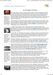
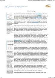
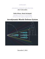
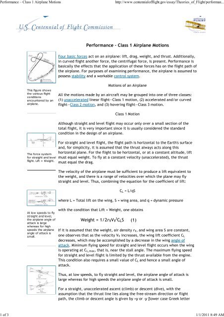
<strong>Performance</strong> – <strong>Class</strong> 1 <strong>Airplane</strong> <strong>Motions</strong>http://www.centennialofflight.gov/essay/Theories_of_Flight/performan...1 of 3 1/1/2011 8:49 AM<strong>Performance</strong> – <strong>Class</strong> 1 <strong>Airplane</strong> <strong>Motions</strong>Four basic forces act on an airplane: lift, drag, weight, and thrust. Additionally,in curved flight another force, the centrifugal force, is present. <strong>Performance</strong> isbasically the effects that the application of these forces has on the flight path ofthe airplane. For purposes of examining performance, the airplane is assumed topossess stability and a workable control system.This figure showsthe various flightconditionsencountered by anairplane.<strong>Motions</strong> of an <strong>Airplane</strong>All the motions made by an aircraft may be grouped into one of three classes:(1) unaccelerated linear flight—<strong>Class</strong> 1 motion, (2) accelerated and/or curvedflight—<strong>Class</strong> 2 motion, and (3) hovering flight—<strong>Class</strong> 3 motion.<strong>Class</strong> 1 MotionAlthough straight and level flight may occur only over a small section of thetotal flight, it is very important since it is usually considered the standardcondition in the design of an airplane.The force systemfor straight and levelflight. Lift = Weight.For straight and level flight, the flight path is horizontal to the Earth's surfaceand, for simplicity, it is assumed that the thrust always acts along thishorizontal plane. For the flight to be horizontal, or at a constant altitude, liftmust equal weight. To fly at a constant velocity (unaccelerated), the thrustmust equal the drag.The velocity of the airplane must be sufficient to produce a lift equivalent tothe weight, and there is a range of velocities over which the plane may flystraight and level. Thus, combining the equation for the coefficient of lift:C L = L/qSwhere L = Total lift on the wing, S = wing area, and q = dynamic pressureAt low speeds to flystraight and level,the airplane angle ofattack is largewhereas for highspeeds the airplaneangle of attack issmall.with the condition that Lift = Weight, one obtainsWeight = 1/2r ¥ V ¥ 2 C L S (1)If it is assumed that the weight, air density r ¥ , and wing area S are constant,one observes that as the velocity V ¥ increases, the wing lift coefficient C Ldecreases, which may be accomplished by a decrease in the wing angle ofattack. Minimum flying speed for straight and level flight occurs when the wingis operating at C L,max , that is, near the stall angle. The maximum flying speedfor straight and level flight is limited by the thrust available from the engine.This condition also requires a small value of C L and hence a small angle ofattack.Thus, at low speeds, to fly straight and level, the airplane angle of attack islarge whereas for high speeds the airplane angle of attack is small.For a straight, unaccelerated ascent (climb) or descent (dive), with theassumption that the thrust line lies along the free-stream direction or flightpath, the climb or descent angle is given by +y or -y [lower case Greek letter
<strong>Performance</strong> – <strong>Class</strong> 1 <strong>Airplane</strong> <strong>Motions</strong>http://www.centennialofflight.gov/essay/Theories_of_Flight/performan...2 of 3 1/1/2011 8:49 AMFigures (a) and (b)show the forcesystems for anairplane in astraight-constantvelocity climb ordive an angle to thehorizontal directionof flight.gamma], respectively. If the forces are summed parallel and perpendicular tothe flight path, it is seen that the weight force is resolved into two components.One obtainsL = W cos y = W cos (-y ) (Climb or dive)T = D + W sin y (Climb)T = D + W sin (-y ) = D - W sin y (Dive) (1)To maintain a straight climbing (or diving) flight path, the lift equals thecomponent of weight perpendicular to the flight path.L = W cos y = W cos (-y)In the case of the climb condition to maintain a constant velocity, the thrustmust equal the drag plus a weight component retarding the forward motion ofthe airplane. In the case of the dive condition, the weight component along theflight path helps the thrust by reducing the drag component for constantvelocity.This figure showsthe force systemsfor an airplane in astraight, constantvelocity verticalclimb (straight up).The conclusion is that one must use an increased thrust to climb at constantvelocity and use less thrust to dive at constant velocity. This is analogous to thesituation of a car where one must "give it the gas" (apply more thrust) toprevent the car from slowing down in going up a hill and "let up on the gas" (useless thrust) to prevent the car from speeding up when going down a hill.It is interesting also to examine three special cases of the use of the aboveequations. First, in straight and level flight, the climb angle y is zero, hence siny = 0 and cos y = 1. This yields the previously derived conditions that Lift =Weight (L = W) and Thrust = Drag (T = D). Secondly in a vertical climb y = 90°,and hence sin y = 1 and cos y = 0. Thus, the thrust necessary to climb verticallyis equal to the drag plus the airplane weight (T = D + W). Also, for a verticalclimb, the lift equals zero (L = 0).The final condition to be discussed is gliding flight. In gliding flight, the thrustequals zero. It is therefore necessary to balance the forces of lift and drag withthe weight. Equation (2) remains unchanged but equation (1) is simplified. In aglide:L = W cosy g (2)D = W siny g (3)If one divides equation (2) by equation (3), the result is:L/D = 1/tany gIn nonmathematical language, this means that the smallest glide angle, andhence maximum gliding range, is obtained when the lift-drag ratio is themaximum. The lift-drag ratio is a measure of the aerodynamic efficiency of theairplane. Sailplanes possess the greatest lift-drag ratios with excellentaerodynamic design since they rely on air currents to keep them aloft. For aparticular airplane, the lift-drag ratio varies with the angle of attack of theairplane (not to be confused with the glide angle of the flight path). There is aparticular angle of attack for which this ratio is a maximum. This is then theangle of attack for minimum glide angle and maximum range. For any otherangle of attack, the lift-drag ratio is less and the glide angle is increased; hence,a steeper glide results. It is a natural tendency for a pilot to raise the airplane'snose (increase the angle of attack) to try to get maximum range, but unless thisgives the maximum lift-drag ratio, the descent will be steeper instead.
<strong>Performance</strong> – <strong>Class</strong> 1 <strong>Airplane</strong> <strong>Motions</strong>http://www.centennialofflight.gov/essay/Theories_of_Flight/performan...3 of 3 1/1/2011 8:49 AM—Adapted from Talay, Theodore A. Introduction to the Aerodynamics of Flight.SP-367, Scientific and Technical Information Office, National Aeronautics andSpace Administration, Washington, D.C. 1975. Available athttp://history.nasa.gov/SP-367/cover367.htmFor Further Reading:Anderson, Jr., John D. A History of Aerodynamics. Cambridge, England:Cambridge University Press, 1997.Hewitt, Paul G. Conceptual Physics. Sixth Edition. Glenview, Ill.: Scott,Foresman and Company, 1989.Smith, Hubert. The Illustrated Guide to Aerodynamics, 2 nd edition. Blue RidgeSummit, Pa.: TAB Books, 1992.Wegener, Peter P. What Makes <strong>Airplane</strong>s Fly? New York: Springer-Verlag, 1991.EducationalOrganizationInternationalTechnology EducationAssociationInternationalTechnology EducationAssociationStandard Designation(where applicableStandard 2Standard 9Content of StandardStudents will develop anunderstanding of the coreconcepts of technology.Students will develop anunderstanding ofengineering design.Home | About Us | Calendar | Wright Brothers History | History of Flight | Sights & Sounds | Licensed Products | Education | Links | Sitemap
![p density of fluid, kg/m3 [Greek letter rho] V mean velocity of fluid, m ...](https://img.yumpu.com/50595898/1/184x260/p-density-of-fluid-kg-m3-greek-letter-rho-v-mean-velocity-of-fluid-m-.jpg?quality=85)