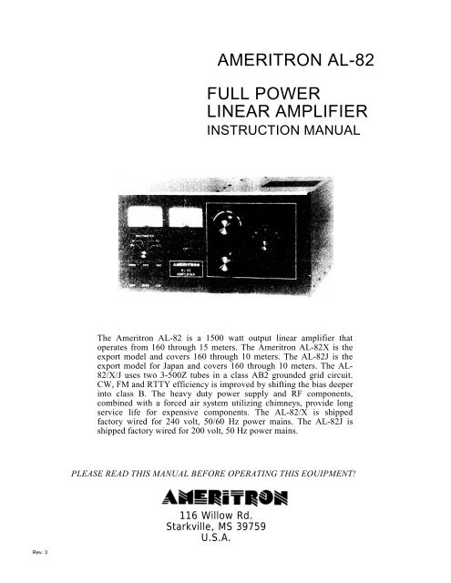
AMERITRON AL-82 FULL POWER LINEAR AMPLIFIER - Ad4c.us
AMERITRON AL-82 FULL POWER LINEAR AMPLIFIER - Ad4c.us
AMERITRON AL-82 FULL POWER LINEAR AMPLIFIER - Ad4c.us

Create successful ePaper yourself
Turn your PDF publications into a flip-book with our unique Google optimized e-Paper software.
<strong>AMERITRON</strong> <strong>AL</strong>-<strong>82</strong><br />
<strong>FULL</strong> <strong>POWER</strong><br />
<strong>LINEAR</strong> <strong>AMPLIFIER</strong><br />
INSTRUCTION MANU<strong>AL</strong><br />
The Ameritron <strong>AL</strong>-<strong>82</strong> is a 1500 watt output linear amplifier that<br />
operates from 160 through 15 meters. The Ameritron <strong>AL</strong>-<strong>82</strong>X is the<br />
export model and covers 160 through 10 meters. The <strong>AL</strong>-<strong>82</strong>J is the<br />
export model for Japan and covers 160 through 10 meters. The <strong>AL</strong>-<br />
<strong>82</strong>/X/J <strong>us</strong>es two 3-500Z tubes in a class AB2 grounded grid circuit.<br />
CW, FM and RTTY efficiency is improved by shifting the bias deeper<br />
into class B. The heavy duty power supply and RF components,<br />
combined with a forced air system utilizing chimneys, provide long<br />
service life for expensive components. The <strong>AL</strong>-<strong>82</strong>/X is shipped<br />
factory wired for 240 volt, 50/60 Hz power mains. The <strong>AL</strong>-<strong>82</strong>J is<br />
shipped factory wired for 200 volt, 50 Hz power mains.<br />
PLEASE READ THIS MANU<strong>AL</strong> BEFORE OPERATING THIS EQUIPMENT!<br />
116 Willow Rd.<br />
Starkville, MS 39759<br />
U.S.A.<br />
Rev. 3
UNPACKING INSTRUCTIONS<br />
1. Carefully remove the amplifier, transformer, and tube from their shipping cartons.<br />
Inspect each item for visible damage. If any damage occurred during shipment,<br />
notify the transportation company immediately.<br />
2. Save all packing materials in case you need to return your <strong>AL</strong>-<strong>82</strong>/X/J for factory<br />
service. The cartons have been designed to give maximum protection for this<br />
amplifier. Any units returned without proper packing may be damaged and shipping<br />
claims cannot be made. Contact the factory before returning any units.<br />
3. Remove the screws that hold the cover to the amplifier. Slide the cover back and<br />
remove it from the amplifier. Remove the package that is in the space where the<br />
transformer will be installed. This package contains two chimneys for the 3-500Zs.<br />
Follow the Tube Installation steps on page 5 to properly install the chimneys. There is a<br />
small bag that contains the f<strong>us</strong>es, f<strong>us</strong>e caps and the remainder of the chassis screws<br />
wrapped in the packing material around the anode connectors.<br />
4. Please read the GENER<strong>AL</strong> INFORMATION and SPECIFICATIONS sections<br />
before attempting to install the transformer and tube. Go to the INST<strong>AL</strong>LATION<br />
section on page 4 to begin installing the transformer and tube.<br />
5. This amplifier m<strong>us</strong>t always be disconnected from the power mains before removing<br />
the cover. See the precaution on page 10. Please read the entire manual to become<br />
familiar with the operation of the <strong>AL</strong>-<strong>82</strong>/X/J amplifier before attempting to operate this<br />
equipment.<br />
NOTE: The <strong>AL</strong>-<strong>82</strong>J is the Japanese export version of the <strong>AL</strong>-<strong>82</strong> amplifier. The <strong>AL</strong>-<br />
<strong>82</strong>J utilizes a special power transformer for <strong>us</strong>e with 200V AC, 50 Hz. The <strong>AL</strong>-<strong>82</strong>J<br />
will perform to specifications when the special transformer supplied is installed and it<br />
will cover 160 through 10 meters.
1. Inexpensive tubes: the <strong>AL</strong><strong>82</strong> <strong>us</strong>es a pair of rugged 3-<br />
500z tubes.<br />
2. Fast warm-up time: the 3-500z requires only a few<br />
seconds of warm-up time.<br />
FEATURES<br />
6. Two Illuminated Panel Meters: the <strong>AL</strong>-<strong>82</strong> has two illuminated<br />
panel meters. The Grid Current meter provides<br />
a continuo<strong>us</strong> reading of grid current and indicates proper<br />
operation of the amplifier. The other meter reads Plate<br />
Voltage (HV), Plate Current (IP), Peak RF Watts ( P O )<br />
and <strong>AL</strong>C.<br />
3. SSB/CW switch: the bias voltage is switched to provide<br />
the best linearity on SSB or the lowest dissipation on<br />
CW operation.<br />
4. <strong>AL</strong>C Indicator: the drive level is detected to provide a<br />
control voltage for the exciter. <strong>AL</strong>C prevents overdriving<br />
of the linear and reduces distortion from excessive<br />
drive power.<br />
7. Operate/Standby Switch: filament and plate voltages are<br />
maintained while allowing the amplifier to be bypassed<br />
for "barefoot'' operation.<br />
8. 12 Volt Auxiliary Jack: 12 volts at 100 mA is provide for<br />
accessories such as the ATR-15 Antenna tuner.<br />
9. XMT Indicator LED: provides a front panel indication of<br />
proper amplifier keying by the exciter during operation.<br />
5. Vernler Plate and Load Adj<strong>us</strong>tments: both tuning controls<br />
have vernler 6:1 reduction drives for smooth<br />
tuning.<br />
Caution: This amplifier m<strong>us</strong>t be disconnected from the<br />
power mains before removing the cover. See the warning on<br />
page 10.<br />
T ECHNIC<strong>AL</strong> SPECIFICATIONS <strong>AL</strong>-<strong>82</strong><br />
Input<br />
Circuit type: Pi-network, slug tuned coils<br />
maximum VSWR at resonance: 1.2:1 minimum 2:1<br />
VSWR bandwidth: 20% maximum drive power<br />
permissible: 130 watts typical drive for full power<br />
output: 100 watts<br />
Output<br />
circuit type: Pi-L, Pi<br />
1 /2 hour continuo<strong>us</strong> carrier: 1500 watts (Below 18mHZ)<br />
30 second continuo<strong>us</strong> carrier: 1800 watts pl<strong>us</strong><br />
1 /2 hour PEP two-tone test: 1800 watts<br />
30 second PEP two-tone test:1800 watts pl<strong>us</strong><br />
Power Supply<br />
circuit type: full wave bridge, capacitor input no<br />
load voltage: 3800V<br />
full load voltage: 3300V full load current: .8 amp<br />
regulation: 10% or better transformer: 32 lbs., hypersil<br />
capacitors: 26 mfd total, computer grade maximum<br />
draw at rated output: 13 amps at 240V AC -50/60 Hz<br />
Tube<br />
type (2) 3-500Z continuo<strong>us</strong> dissipation: 1000<br />
watts warm-up time: approximately 30<br />
seconds<br />
Metering: multimeter: plate current, plate voltage,<br />
drive/<strong>AL</strong>C, power output (PEP watts). Grid: grid current<br />
<strong>AL</strong>C: negative going, 0-20V, adj<strong>us</strong>table, phono jack<br />
Efficiency CW: 65% typical<br />
Efficiency SSB (envelope crest): 62% typical<br />
MARSIWARC: yes, bandswitch set to nearest amateur band<br />
Keying: requires relay closure or sinking to ground of<br />
positive (+) 12 VDC at 100 mA, phono jack<br />
RF Connectors: S0239<br />
Line Connector: NEMA 6-15P 240V style<br />
Dimensions: 18 1/2" D x 17" W x 10"H<br />
Weight: 77 lbs.<br />
Frequency Coverage: (<strong>AL</strong>-<strong>82</strong>)-1.8, 3.5, 7, 14, 18 and 21<br />
MHz. User modified models cover 24 and 28 MHz. (<strong>AL</strong>-<br />
<strong>82</strong>X/J)Export models-1.8, 3.5, 7, 14, 18, 21, 24 and 28<br />
MHz.<br />
Third Order IMD at Rated Output: -34 dB at 1500 w output
SAFETY INTERLOCK<br />
While the Amplifier's top cover is in place, the interlock switch<br />
closes to allow AC line voltage to reach the power transformer.<br />
When the top cover is removed, the interlock opens and<br />
disconnects the line voltage. This does not discharge the bank of<br />
power supply filter capacitors. Be sure to allow the filter<br />
capacitors to discharge before you touch anything inside the<br />
Amplifier. You can select the High Voltage function of the<br />
Multimeter to check the high voltage potential. Never attempt to<br />
defeat the safety interlock. WARNING- Never remove the cover<br />
of this amplifier with the unit plugged into the power line.<br />
DRIVING <strong>POWER</strong><br />
This Amplifier is designed to operate at full ratings when it is<br />
driven by an exciter that has approximately 100 watts of RF<br />
output. You can <strong>us</strong>e an exciter that has lower output power, but<br />
the Amplifier's output will be less. If you <strong>us</strong>e an exciter that<br />
delivers more than 100 watts, carefully adj<strong>us</strong>t the driving power<br />
to avoid "over drive" and the creation of spurio<strong>us</strong> signals, which<br />
create needless interference to other operators. We highly<br />
recommend that you <strong>us</strong>e a monitor scope for continuo<strong>us</strong> output<br />
monitoring. The display on an oscilloscope is the best way of<br />
determining the amplitude of the voice peaks which, if<br />
excessive, can ca<strong>us</strong>e "flat topping" and splatter.<br />
IMPORTANT: In no case should you advance the power output<br />
control of your exciter beyond the point where the Amplifier's<br />
Power Output indication ceases to increase. If you turn the<br />
control past this point, nonlinear operation may occur.<br />
FILAMENT SUPPLY<br />
The filament circuit of this amplifier satisfies all requirements<br />
of the tube manufacturer related to tube performance and life.<br />
Inr<strong>us</strong>h current is controlled by the transformer internal<br />
resistance and impedance, filament choke resistance and<br />
filament wiring resistance. To insure maximum life of the tube<br />
never replace any circuit components or wiring with substitute<br />
parts.<br />
The low voltage tap on the filament transformer primary provides<br />
the ability to operate the blower at slower speeds for<br />
reduced noise. Normal amateur operation in CW and SSB will<br />
not ca<strong>us</strong>e heat damage to components on any recommended tap.<br />
It is always advisable to <strong>us</strong>e the maximum speed (air flow) that<br />
the level of noise permits to extend component life. Wiring<br />
information for the blower is shown in the "Transformer<br />
Connections" instructions on page 6.<br />
The high voltage present on the plate choke and air variable<br />
capacitors attracts d<strong>us</strong>t and dirt out of the air stream. It is<br />
particularly important that the high voltage areas at the bottom<br />
of the plate choke and the insulators on the air variable<br />
capacitors be d<strong>us</strong>t free. These areas should be inspected every<br />
few months if the amplifier is operated in a d<strong>us</strong>ty environment.<br />
Unplug the line cord, and wait about 90 seconds until the power<br />
supply capacitors discharge. Check the HV scale for zero<br />
voltage before removing the cover. Remove the cover and<br />
connect a jumper wire from ground to the anode connection of<br />
the tubes.<br />
GENER<strong>AL</strong> INFORMATION<br />
PLATE SUPPLY<br />
The plate supply has a full wave bridge rectifier and a 1.8 KVA<br />
CCS rated tape wound hypersil transformer. Filtering is<br />
accomplished by a bank of high quality capacitors totaling 26<br />
mfd (additional capacitance will not improve supply<br />
performance). The Plate Supply will not be harmed by normal<br />
continuo<strong>us</strong> amateur operation at 1500 watt levels. Power is<br />
applied through RLY2 when the 12V DC low voltage supply is<br />
activated. A 10 ohm resistor limits the line current during the<br />
filter capacitor charge time to lower the stress on components.<br />
When the primary voltage approaches the full line value, RLY3<br />
shorts the 10 ohm resistor and applies the full line voltage to the<br />
plate transformer. The 10 ohm resistor acts as a f<strong>us</strong>e during startup<br />
if the high voltage supply has a short.<br />
EXPORT MODIFICATIONS<br />
A simple modification will allow operation on frequencies above<br />
15 meters. Instructions for this modification are available by<br />
sending a written request for "Export Modification Instructions"<br />
along with a copy of a valid amateur license. There is no charge<br />
for this information. Export models are shipped with this<br />
modification and have an "X" or "J" following the serial number.<br />
Standard frequency coverages are indicated in the chart<br />
following the tuning instructions on page 10.<br />
TECHNIC<strong>AL</strong> ASSISTANCE<br />
PERIODIC MAINTENANCE<br />
Technical assistance is available during our normal b<strong>us</strong>iness<br />
hours on weekdays. The following information is required to<br />
assist you with operational problems:<br />
1. Name and daytime phone number<br />
2. Model and Serial Number<br />
3. Date of purchase and dealer<br />
Meter readings at all stages of the tuning proceedure are very<br />
important along with a complete description of the other<br />
equipment <strong>us</strong>ed with our product.<br />
Written assistance is also available. Due to time delays in<br />
processing mail, please allow at least three weeks for a written<br />
reply<br />
<strong>AMERITRON</strong><br />
116 Willow Rd. Starkville,<br />
Ms. 39759 Telephone<br />
(601)323-<strong>82</strong>11 FAX (601)<br />
NOTE: This is a safety wire that m<strong>us</strong>t be installed when<br />
beginning service work. After service is complete, reverse the<br />
procedure to remove the safety wire. Remove the wire from the<br />
anode connection first and then from ground.<br />
Use a soft bristle br<strong>us</strong>h dipped in alcohol to clean areas mentioned<br />
previo<strong>us</strong>ly. In the event that cleaning is required at<br />
frequent intervals, place a low restriction air filter material over<br />
the air inlet holes on the left front side of the cabinet near the<br />
filter capacitors. Most hardware stores stock suitable materials<br />
that are <strong>us</strong>ed as replacement filters for window air conditioners.
The <strong>AL</strong>-<strong>82</strong> has two illuminated meters. The Grid Current meter provides<br />
a continuo<strong>us</strong> indication of the two 3-500z grid current. This excl<strong>us</strong>ive<br />
feature of Ameritron amplifiers indicates proper amplifier operation better<br />
than any other parameter. Do not exceed 300 mA on this meter during<br />
normal operation of this amplifier. The other meter reads Plate Voltage<br />
(HV), Plate Current (Ip), Peak RF Watts (PO) and <strong>AL</strong>C. These functions<br />
are selected with the Multimeter Switch.<br />
Plate Voltage (HV): Read DC Plate Voltage on the 4000 volt scale. This<br />
scale is 100 volts per division. Normal voltages are 3600 volts no load,<br />
3300 volts full load.<br />
Plate Current (Ip): Read Plate current on the 1000 mA scale. This scale is<br />
25 mA per division. The maximum operating current rating of the 3-500z<br />
is 400 mA SSB or 900<br />
mA CW.<br />
TRANSFORMER INST<strong>AL</strong>LATION<br />
Remove the cover of the amplifier. Remove the package that is in the<br />
plate transformer area. This package contains the chimneys for the <strong>AL</strong>-<br />
<strong>82</strong>. There is a small bag that contains the f<strong>us</strong>es, f<strong>us</strong>e caps and the<br />
remainder of the chassis screws wrapped in the packing material around<br />
the anode connector. Remove the top 7/16" nuts from the four<br />
transformer mounting bolts inside of the amplifier. Carefully remove the<br />
transformer from its shipping carton.<br />
METERING FUNCTIONS<br />
INST<strong>AL</strong>LATION<br />
Peak RF Watts (PO): Read Peak RF Watts on the 2000 watt scale. This<br />
scale has 50 watt divisions below 1000 watts and 100 watt divisions above<br />
1000 watts.<br />
NOTE: This circuit <strong>us</strong>es an emitter follower to charge a capacitor to<br />
the peak envelope voltage detected by the <strong>AL</strong>C/Power Board. Accurate<br />
peak envelope power readings are given when the amplifier is connected<br />
to a 50 ohm nonreactive load. If the amplifier is <strong>us</strong>ed with a mismatched<br />
load, the power meter will read higher or lower than normal by a ratio up<br />
to the value of the SWR. Potentiometer R5 on the Meter Board (50-01140-<br />
1) adj<strong>us</strong>ts the calibration of the power meter.<br />
<strong>AL</strong>C: Indicates a relative drive level (average, not PEP) that can be<br />
estimated by dividing the Peak RF Watts scale by 10.<br />
Remove the brass 1 /4" hex nuts and the top flat washer from the two 6-32<br />
screws on the rectifier board (see Fig. 1). Install the RED lead ring<br />
terminals on the screws and replace the flat washers and 1 /4" hex nuts.<br />
Position the wires so that the black insulated areas are at least 1 /4" from<br />
each other and any metal objects. Now tighten the 1 /4" hex nuts.<br />
For 240V Operation (factory wired):<br />
Place the transformer on the four 1 /4-20 mounting bolts. Use care beca<strong>us</strong>e<br />
the transformer is heavy. The side with the two high voltage secondary<br />
RED leads m<strong>us</strong>t be adjacent to the center panel(see Fig. 1). Now place a<br />
7/16" nut on each bolt (see Fig. 2). Snug the nuts down manually. Do not<br />
tighten with a ratchet wrench.<br />
The four primary leads have colored plastic insulating boots over the quick<br />
disconnect terminals. Slide these back prior to installing the leads. Install<br />
the color coded boots as follows:(see Fig. 1)NOTE: Japanese export<br />
model (<strong>AL</strong>-<strong>82</strong>J) <strong>82</strong>J) should follow the 240V operation steps to properly<br />
connect their transformer. The <strong>AL</strong>-<strong>82</strong>J is supplied with a special<br />
transformer for 200V operation.<br />
1. BLUE (Brown wire) to the top relay terminal<br />
2. YELLOW (Black/White) to the top terminal of terminal block<br />
3. CLEAR (Black wire) to the second terminal of terminal block<br />
4. RED (Brn/Wht) to the bottom terminal of terminal block<br />
Now slide the colored insulating boots back over the terminals. NOTE:<br />
The green wire is not <strong>us</strong>ed for 240V operation. There is no green wire on<br />
the <strong>AL</strong>-<strong>82</strong>J export model transformer.<br />
Important: The leads m<strong>us</strong>t be in the positions indicated by the color coded<br />
insulating boots (see Fig. 1) for 240V operation, or for 200V operation in<br />
Japan. For 220V operation, see page 5. Caution: Do not <strong>us</strong>e the 220V<br />
wiring unless the line voltage is always below 220 VAC. The Standard<br />
USA voltage is 240 VAC, not 220.
TRANSFORMER INST<strong>AL</strong>LATION<br />
For 220V connections(see Fig. 3), follow the first three<br />
steps on the 240V operation on page 4, then follow the<br />
steps below:<br />
1. Slide the RED boot back on the BRN/WHT<br />
wire<br />
2. Clip the terminal connector off the wire and<br />
slide the RED boot off.<br />
3. Remove the restraint from the GRN wire and<br />
slide the RED boot on to the wire.<br />
4. Solder the terminal connector to the GRN wire.<br />
5. Tape up the BRN/WHT wire beca<strong>us</strong>e it will not<br />
be <strong>us</strong>ed.<br />
Install the tubes, chimneys, anode. bracket and plate cap<br />
connectors as follows: (see Fig. 4)<br />
1. After removing the packing material from<br />
around the anode connectors, install the 3-<br />
500z tubes. NOTE: One of the tube pins is<br />
offset. This offset pin "keys" the tube base<br />
and socket. Install the tube by aligning the<br />
tube pins with the socket contact terminals,<br />
then seat the tube with vertical pressure ON-<br />
LY. Do not "rock" or "twist" the tube.<br />
TUBE INST<strong>AL</strong>LATON<br />
Fig.<br />
2. Place the chimneys over the tubes and seat with<br />
the metal clips inside each chimney. Do not<br />
apply excessive force or the glass chimney<br />
may crack.<br />
3. Attach the blocking capacitors to the anode<br />
bracket and secure with the two 6/32 screws.<br />
4. install the plate cap connectors on the tubes in<br />
the positions shown. Be careful not to drop<br />
any hardware inside the chassis.<br />
Fig. 4 Top View of 3-500z tubes
Caution: This page is only valid for transformers that contain these exact color codes for the primary winding. Early<br />
production units did not contain a multiple tap transformer. If the terminal strip has all these color coded wires, then the<br />
unit has the multiple tap transformer.<br />
FILAMENT/BLOWER WIRING INSTRUCTIONS<br />
The <strong>AL</strong>-<strong>82</strong> and <strong>82</strong>(X) amplifiers come prewired for 240V line voltage and with the blower prewired for medium high<br />
fan speed. NOTE: The <strong>AL</strong>-<strong>82</strong>J Japanese export model is prewired for 208V line voltage and with the blower prewired<br />
for medium high fan speed.. This page gives filament transformer connection details for vario<strong>us</strong> line voltages and<br />
blower speeds. The five lug terminal strip and the single lug terminal strip are located immediately behind the ON/OFF<br />
rocker switch inside the unit. The drawing below shows the connection of transformer leads and their purpose.<br />
This chart shows the color code of the transformer leads and their purpose. The number in parenthesis<br />
indicates the number of the terminal lug that the transformer lead is connected to. The<br />
number three (3) lug is not <strong>us</strong>ed to change the filament or blower wiring. Do not add or remove<br />
any wires from the number three (3) lug. Refer to the drawing above. Use the lug numbers above<br />
when referring to both of the Filament connection chart and the Blower connection chart below.<br />
FILAMENT TRANSFORMER LINE VOLTAGE There<br />
are two wires that connect to the terminal lugs which<br />
determine the Filament Line Voltage. The BLACK wire<br />
from the power switch and WHITE wire from rear of the<br />
unit connect to different terminal lugs depending on the<br />
voltage desired. The <strong>AL</strong>-<strong>82</strong> and <strong>82</strong>(X) come prewired for<br />
240V operation`. <strong>AL</strong>-<strong>82</strong>J comes prewired for 200V<br />
operation". Refer to the chart below. The voltage listed in<br />
the chart below is the maximum line voltage that should be<br />
applied to a given tap. Operation with line voltage in<br />
excess of the tap voltage selected can result in a reduction<br />
of tube life.<br />
BLOWER CONNECTIONS<br />
The GREEN and WHITE wires from the rear of the unit<br />
connect to the terminal lugs to control the air speed of the<br />
fan. The <strong>AL</strong>-<strong>82</strong>/X/J are prewired for the medium high speed<br />
setting'. Refer to the chart below. The blower connections<br />
can be moved to lower speed taps if air noise is excessive.<br />
Ameritron recommends <strong>us</strong>ing the highest speed tap that<br />
noise considerations permit. The lowest speed tap will<br />
develop sufficient air flow for standard amateur SSB and<br />
CW full power operation. The highest speed taps should be<br />
<strong>us</strong>ed for contest or RTTY operation.<br />
* indicates factory shipped (<strong>AL</strong>-<strong>82</strong>/X) * *<br />
indicates factory shipped (<strong>AL</strong>-<strong>82</strong>)J<br />
* indicates factory shipped
INTERCONNECTION<br />
1. Connect the RF output of the exciter to the RF IN connector<br />
on the rear of the <strong>AL</strong>-<strong>82</strong> with 50 ohm coax. Use any good<br />
quality 50 ohm cable long enough to connect the amplifier to<br />
the exciter. The amplifier <strong>us</strong>es a standard SO-239 female that<br />
will mate to a PL-259 male connector on the cable.<br />
2. Connect the existing station antenna system to the RF OUT<br />
connector on the rear of the <strong>AL</strong>-<strong>82</strong> with RG-8 type coax. This<br />
connection <strong>us</strong>es PL-259 connectors.<br />
3. Use shielded audio type cable with standard male phono<br />
plugs to connect to the RELAY jack on the <strong>AL</strong>-<strong>82</strong>. This jack<br />
has positive 12V DC open circuit and supplies<br />
100mA of current when pulled to ground.<br />
4. Connect a short ground lead from a good earth and RF ground<br />
to the GND terminal.<br />
5. The 12V connection on the rear panel provides 12V DC at 100<br />
mA maximum to operate external dial lamps or accessories such<br />
as the ATR-15 Antenna Tuner.<br />
6. DO NOT CONNECT THE "<strong>AL</strong>C OUT" SOCKET ON THE<br />
<strong>AMPLIFIER</strong> TO THE "<strong>AL</strong>C" SOCKET ON THE<br />
TRANSMITTER UNTIL INSTRUCTED TO DO SO IN THE<br />
TUNE UP PROCEDURE. This jack provides up to 20 Volts of<br />
negative voltage for transmitter gain control.
LOCATION<br />
Do not operate the Amplifier in excessively warm locations<br />
or near heating vents or radiators. Be sure air can circulate<br />
freely around and through the Amplifier cabinet. Provide an<br />
unobstructed air inlet for the blower. Do NOT place anything<br />
that will impede the free flow of air within 2 inches of the<br />
cabinet ventilation holes.<br />
VENTILATION<br />
The <strong>AL</strong>-<strong>82</strong> ventilation system has been designed and tested<br />
to maintain tube seal temperature safely below the tube<br />
manufacturer's rating at 1500 watts output with a 100% duty<br />
cycle when properly tuned. The blower in the <strong>AL</strong>-<strong>82</strong> is a<br />
permanently lubricated type that requires no maintainence in<br />
normal operation. To insure proper ventilation in your installation,<br />
observe the following:<br />
1. Do not block or unduly restrict the ventilation holes in the<br />
cover. Be sure that the amplifier is located in an area so<br />
the vent holes have open air circulation.<br />
2. The exha<strong>us</strong>t air flow is over 30 CFM. Do not "assist" the<br />
air flow unless the fan exceeds the <strong>AL</strong>-<strong>82</strong> blower CFM<br />
by a factor of 2:1.<br />
3. Do not mount additional fans on the <strong>AL</strong>-<strong>82</strong> cabinet.<br />
4. The exha<strong>us</strong>t air will become quite warm at higher power<br />
levels. Do not place any heat sensitive objects in the<br />
exha<strong>us</strong>t air stream.<br />
INST<strong>AL</strong>LATION Cont.<br />
<strong>POWER</strong> CONNECTIONS<br />
The <strong>AL</strong>-<strong>82</strong> is supplied with a NEMA 6-15P plug for 240V<br />
AC operation. Operation with power main voltages below 200<br />
volt is not 'recommended. A special transformer is required<br />
for 200\/, 50/60 Hz operation (see NOTE on page 1). Refer to<br />
the "Transformer Installation" section on pages 4 and 5 for the<br />
correct wiring for 220 to 240 volt operation.<br />
NEVER REWIRE THE <strong>POWER</strong> SUPPLY TO BOOST THE<br />
HIGH VOLTAGE ABOVE 3700 VOLTS.<br />
The wiring between the f<strong>us</strong>e box and the amplifier AC outlet<br />
m<strong>us</strong>t be No. 12 gauge or larger in order to supply the current<br />
required (13 amperes) without a significant drop in the line<br />
voltage. The outlet should be f<strong>us</strong>ed for 20 amperes.<br />
GROUNDING<br />
TUNING INSTRUCTIONS<br />
Connect a good RF and earth or water pipe ground to the<br />
ground post on the rear panel of the Amplifier. Use the<br />
heaviest and shortest connection possible.<br />
Before you <strong>us</strong>e a water pipe ground, inspect the connections<br />
around the water meter and make sure that no plastic or rubber<br />
hose connections are <strong>us</strong>ed. These connections interrupt<br />
electrical continuity to the water supply line. Install a jumper<br />
around any insulating water connections you may find. Use<br />
heavy copper wire and pipe clamps. It is best to ground all<br />
equipment to one point at the operating position and then<br />
ground this point as described above.<br />
Proper tuning of a grounded grid linear amplifier is best<br />
accomplished with an understanding of what each control<br />
does and v.hat the meters are telling the operator about the<br />
condition of TUNE.<br />
The tuning controls function as follows:<br />
PLATE: This control tunes the amplifier output circuit to the<br />
operating frequency. It should always be adj<strong>us</strong>ted for<br />
maximum output power or maximum grid current. Due to<br />
interaction with the "LOAD" control, a "touch-up'' should be<br />
performed after any load adj<strong>us</strong>tments.<br />
LOAD: This control adj<strong>us</strong>ts the coupling of amplifier to the<br />
antenna or load. It should be adj<strong>us</strong>ted to keep the grid current<br />
in the proper operating range. As the loading capacitance is<br />
reduced (by rotating the control to a higher front panel<br />
number), the coupling is increased. An increase in coupling<br />
will reduce grid current and increase the amount of drive the<br />
amplifier will accept without component damage.<br />
A common mistake in tuning is to adj<strong>us</strong>t the "LOAD" control<br />
at low drive powers and apply more drive dur<br />
ing operation. Excessive grid current, distortion on SSB or<br />
arcing in the tank components occurs when full drive power is<br />
applied to the amplifier without the "LOAD" set far enough<br />
clockwise (higher loading).<br />
It is important to remember the loading m<strong>us</strong>t be set properly<br />
for the PEAK power the amplifier is expected to develop. 50<br />
watts PEP will be the maximum drive the amplifier will safely<br />
handle if the output of the amplifier is tuned with 50 watts of<br />
carrier drive. Any attempt to go beyond the amount of drive<br />
power the amplifier was originally tuned at will result in a<br />
rapid increase in grid current, splatter and even damage to<br />
components.<br />
The "LOAD" control should be adj<strong>us</strong>ted for maximum output<br />
power without exceeding the recommended grid current. DO<br />
NOT USE THE LOAD CONTROL TO REDUCE <strong>POWER</strong><br />
IN A GROUNDED GRID <strong>AMPLIFIER</strong>. The drive from the<br />
exciter should be reduced if the amplifier plate current or<br />
output power is excessive. The "LOAD" setting should be<br />
increased if grid current is excessive. Any errors in adj<strong>us</strong>ting<br />
this control should be made in favor of a higher load setting<br />
(clockwise).
CW PROCEDURE<br />
Follow these instructions in numerical order. If the vario<strong>us</strong><br />
meter readings are different than indicated, check the connections<br />
from the exciter to the amplifier and make sure they are<br />
correct. Consult the manual for the exciter.<br />
OPERATION<br />
6. With exciter drive still at zero, place the MULTIMETER<br />
switch in the Ip position. Observe the 1000 mA scale. The<br />
meter should read zero (0). Place the STBYOPR switch in<br />
the OPR position.<br />
Be sure the transformer is correctly installed and wired for your<br />
line voltage. See the "Transformer installation" section on page<br />
4 and 5 for wiring details.<br />
1. Set the <strong>AL</strong>-<strong>82</strong> front panel switches as follows:<br />
<strong>POWER</strong> TO OFF<br />
OPR-STBY TO STBY<br />
SSB-CW TO CW<br />
MULTIMETER TO<br />
2. Plug the AC line cord into the proper voltage outlet.<br />
3. Set the Power Switch to the ON position. The meter lamps<br />
should light and the blower should start. Read the 4000 volt<br />
scale on the Multimeter. It should indicate 3600 volts<br />
nominal and no more than 3700 volts.<br />
4. With the amplifier still on STANDBY, tune the exciter into a<br />
normal 50 ohm load according to the manufacturer's<br />
instructions. Turn the exciter drive fully down after tuning.<br />
5. Place the amplifier mode switch in the CW position, the<br />
bandswitch on the same band as the exciter, the PLATE<br />
control in the dial range for the band selected and the load<br />
control as indicated:<br />
7. Key the exciter (no drive) and observe the plate current on the<br />
1000 mA scale. It should be 75 mA. Place the CW-SSB<br />
switch in the SSB position. Plate current should now read<br />
150 mA. Return the CW-SSB switch to the CW position.<br />
Note: The no drive currents will vary up to 25% due to<br />
component and line voltage tolerences.<br />
8. Apply only enough drive to indicate a grid current of 100 mA<br />
or an Ip of no more than 500mA. Tune the PLATE control<br />
for maximum output power or grid current. It is normal for<br />
the plate current to dip at this point. If the grid current goes<br />
over 150 mA, reduce the drive at once. Unkey the exciter.<br />
9. Place the MULTIMETER switch in the PO position and<br />
observe the 2000 Peak RF Watts scale. Increase the drive<br />
until 200 mA of grid current is indicated. Adj<strong>us</strong>t the LOAD<br />
and PLATE controls for maximum output. The grid current<br />
may be lower now.<br />
10. Advance the drive to 250 mA of grid current. Adj<strong>us</strong>t the<br />
LOAD and PLATE controls for maximum output power.<br />
The output should be over 1000 watts now.<br />
11. Apply enough drive to indicate either 1500 watts of output<br />
power or 300 mA of grid current. Re-peak the LOAD and<br />
PLATE controls. The final grid current should be around<br />
250 mA and the plate current below 900 mA.
<strong>AL</strong>C (Automatic Level Control)<br />
The primary <strong>us</strong>e of the <strong>AL</strong>C is to reduce the input drive power to a safe<br />
level for the <strong>AL</strong>-<strong>82</strong>. The maximum drive that the <strong>AL</strong>-<strong>82</strong> will tolerate is<br />
approximately 130 watts. At this drive level the output of the <strong>AL</strong>-<strong>82</strong> may<br />
be in excess of 2000 watts when properly tuned. The <strong>AL</strong>C should be<br />
connected and adj<strong>us</strong>ted after the amplifier is properly tuned on CW. Use a<br />
shielded audio-type cable with a standard male phono connector to<br />
connect the 0-20 volt negative <strong>AL</strong>C voltage to the exciter <strong>AL</strong>C input.<br />
Consult the exciter manual for proper connection details.<br />
Setting the <strong>AL</strong>C ADJ Control<br />
Proper adj<strong>us</strong>tment of the rear panel <strong>AL</strong>C control can be achieved by the<br />
following steps:<br />
1. Load the amplifier according to the tune-up instructions (with the <strong>AL</strong>C<br />
disconnected from the exciter) to the desired maximum power.<br />
2. Connect the <strong>AL</strong>C line and rotate the <strong>AL</strong>C control fully clockwise<br />
looking at the rear of the unit.<br />
3. Set the MULTIMETER switch to the PO position or observe an<br />
external PEP meter or oscilloscope.<br />
4. Set the transmitter audio control about 20oio higher than normal.<br />
5. Speak in the microphone in a normal tone of voice and observe the<br />
reading on the 2000 RF Watts scale.<br />
o. Adj<strong>us</strong>t the <strong>AL</strong>C ADJ control on the rear panel until the amplifier<br />
output is no more than the desired maximum power obtained in<br />
step 1.<br />
<strong>AL</strong>C will prevent over-power operation.<br />
SSB PROCEDURE<br />
Tune the Exciter and Amplifier as described in "TUNE-UP CW<br />
PROCEDURE'".<br />
1. Place the SSB-CW switch in the SSB position.<br />
2. Adj<strong>us</strong>t the exciter gain control to permit voice peaks to reach the same<br />
value the peak output meter read on CW when fully loaded. The<br />
plate and grid currents should remain well below 50% of the CW<br />
values during normal modulation.<br />
SSTV, FM, RTTY, PACKET, AMTOR:<br />
The plate current should be limited to 600 mA maximum. The grid<br />
current should be limited to 250 mA. Tune the amplifier for peak output<br />
power with the drive reduced to the grid and plate current below the<br />
ratings given.<br />
NOTE:<br />
Some t;xciters will put out short duration high power RF pulses when<br />
first keyed. Exciter power output peaks may reach or exceed full output<br />
level even if the exciter's power control has been adj<strong>us</strong>ted to deliver<br />
reduced power under "keydown" conditions.<br />
The amplifier loading control m<strong>us</strong>t be set high enough (clockwise) to<br />
prevent extremely high energy levels from developing in the plate and<br />
grid circuits of the amplifier. DO NOT "UNDERLOAD" THE<br />
<strong>AMPLIFIER</strong> TO REDUCE <strong>POWER</strong>. Never "retune" the amplifier to<br />
produce higher efficiency with reduced drive. Poor linearity, splatter or<br />
even damage to components may result from failure to follow these<br />
instructions. Excl<strong>us</strong>ive grid current <strong>us</strong>ually indicates that the loading<br />
control is set too far counter-clockwise for the amount of drive being<br />
applied to the amplifier or that something in the antenna system has<br />
changed impedance (arcing) during operation.<br />
The exciter internal <strong>AL</strong>C will maintain linearity. The amplifier<br />
WARNING!!<br />
MAKE NO ATTEMPT TO PUT THIS <strong>AMPLIFIER</strong> IN SERVICE WITH THE COVER<br />
REMOVED! CONTACT WITH VOLTAGES INSIDE THIS <strong>AMPLIFIER</strong> CAN BE<br />
FAT<strong>AL</strong>! <strong>AL</strong>WAYS DISCONNECT THE <strong>AMPLIFIER</strong> FROM THE <strong>POWER</strong> MAINS<br />
AND WAIT FOR THE FILTER CAPACITORS TO DISCHARGE BEFORE REMOVING<br />
THE COVER.
<strong>AL</strong>-<strong>82</strong> SCHEMATIC Power supply shown<br />
wired for 240V operation
PARTS LIST
<strong>AMERITRON</strong> 116<br />
Willow Road<br />
Starkville MS 39759<br />
Limited Warranty<br />
Ameritron warrants to the original purchaser that this product shall be free from<br />
defects in material (except tubes and RF output transistors) or workmanship for<br />
one year from the date of original purchase.<br />
During the warranty period, Ameritron or an authorized Ameritron service facility<br />
will provide free of charge both parts (except tubes and RF output transistors) and<br />
labor necessary to correct defects in material or workmanship<br />
To obtain such warranty service, the original purchaser m<strong>us</strong>t:<br />
(1) Complete and send in the Warranty Registration Card.<br />
(2) Notify Ameritron or its nearest authorized service facility, as soon as<br />
possible after discovery of a possible defect, of:<br />
(a) The model number and serial number, if any;<br />
(b) The identity of the seller and the approximate date of purchase;<br />
(c) A detailed description of the problem, including details on the equipment<br />
(3) Deliver the product to the Ameritron or the nearest authorized service<br />
facility, or ship the same in its original container or equivalent, fully insured and<br />
shipping charges prepaid.<br />
Correct maintenance, repair and <strong>us</strong>e are important to obtain proper performance<br />
from this product. Therefore, carefully read the Instruction Manual. This warranty<br />
does not apply to any defect that Ameritron determines is due to:<br />
(2<br />
)<br />
Improper maintenance or repair, including the installation of parts or accessories<br />
that do not conform to the quality and specifications of the original<br />
parts.<br />
Mis<strong>us</strong>e, ab<strong>us</strong>e, neglect or improper installation.<br />
Accidental or intentional damage.<br />
All implied warranties, if any, terminate one (1) year from the date of<br />
the original purchase.<br />
The foregoing constitutes Ameritron's entire obligation with respect to this product,<br />
and the original purchaser and any <strong>us</strong>er or owner shall have no other remedy and<br />
no claim for incidental or consequential damages. Some states do not allow limitations<br />
on how long an implied warranty lasts or do not allow the excl<strong>us</strong>ion or<br />
limitation of incidental or consequential damage, so the above limitation and<br />
excl<strong>us</strong>ion may not apply to you.<br />
This warranty gives specific legal rights and you may also have other rights which<br />
vary from state to state.<br />
PLEASE RECORD THIS INFORMATION:<br />
Model<br />
Serial<br />
No: Date of Purchase<br />
Purchased From<br />
Warranty Card Mailed