Download - Buderus
Download - Buderus
Download - Buderus

You also want an ePaper? Increase the reach of your titles
YUMPU automatically turns print PDFs into web optimized ePapers that Google loves.
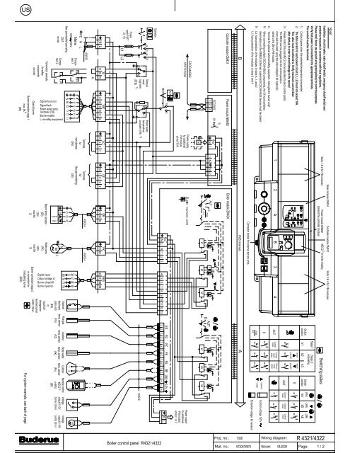
Note!<br />
1)<br />
2)<br />
3)<br />
4)<br />
5)<br />
Contact opens when the selected temperature is exceeded.<br />
The total current for each power circuit (L1, L2) must not exceed 10A.<br />
This value must be adhered to. Verify maximum current draw<br />
after start-up in order to avoid damage to the device!<br />
Please note! Only one MEC2 can be allocated to each control panel.<br />
The MEC2 can be plugged into the control panel or<br />
room wall-mounted using the wall installation kit (optional)<br />
wired to the ZM or FM module.<br />
Terminal for optional external safety equipment. Interrupts the burner only!<br />
When connecting multiple ECOCAN-BUS components, the S1 hook switches<br />
(termination on the NM482) of the two outermost ECOCAN-BUS devices must be closed.<br />
Controller module CM431<br />
Power module NM482<br />
5)<br />
ECO BUS S1<br />
1 2 3<br />
ECOCAN-BUS<br />
AWG18 shieled<br />
AUT<br />
1b<br />
1a<br />
Operation<br />
1<br />
Fuses<br />
each 10AT<br />
1a 1b<br />
1<br />
Manual<br />
reset<br />
high limit<br />
(STB)<br />
1)<br />
4<br />
Boiler water<br />
temperature<br />
controller (TR)<br />
SI<br />
N L<br />
17 18<br />
BR<br />
19<br />
4 8 9 10 11 12<br />
4)<br />
N<br />
/PE<br />
Mains<br />
120V 60Hz<br />
L<br />
Max. permissible fuse rating<br />
20AT<br />
on site<br />
4<br />
N<br />
8 9<br />
B4<br />
S3<br />
10 11<br />
T1<br />
T2<br />
Gas/oil burner<br />
12<br />
Burner connection stage 1<br />
2)<br />
max. 8A<br />
(BR)<br />
L1<br />
Netz<br />
N L<br />
N L<br />
1)<br />
SG<br />
4 5 6<br />
7<br />
Boiler module ZM434<br />
Slots 1 & 2 for FM modules<br />
Controller module CM431<br />
Slots 3 & 4 for FM modules<br />
3)<br />
Power module NM482 MEC2 or boiler display<br />
(behind the controller module)<br />
Switch<br />
position<br />
Stage 1<br />
Stage 2/<br />
modulating<br />
k1 k2 k3<br />
(PK) (SR) (SR)<br />
k4 k5 k6<br />
Button Button<br />
pressed pressed<br />
0<br />
AUT<br />
AUT<br />
Control<br />
mode<br />
Connector socket for external service units<br />
BUS (internal)<br />
0<br />
max<br />
l+ll<br />
Control voltage 120V<br />
Extra-low voltage for sensors<br />
Boiler module ZM434<br />
L1 N N L2<br />
AUT<br />
0<br />
max<br />
l+ll<br />
Netz<br />
0 AUT<br />
k 1<br />
k2<br />
k3<br />
k4 k5 k6<br />
Power supply<br />
for additional<br />
FM module<br />
at slot 1 or 2<br />
ES FG FZ FK FA BF<br />
N L<br />
N L N 1 2 3 4 5 6 7 8 9 10 11 12 13<br />
1 2 1 2 1 2 1 2 1 2<br />
+<br />
AWG18<br />
UE<br />
N 1 2<br />
3 4<br />
SR<br />
41 43<br />
PK<br />
61 63<br />
36<br />
BR II<br />
37<br />
38<br />
39<br />
- +<br />
1 2<br />
AWG14 AWG14<br />
N<br />
M L<br />
36<br />
B5<br />
37 38<br />
T6<br />
T7<br />
39<br />
T8<br />
1<br />
2<br />
1 2<br />
3)<br />
For system example, see back of page<br />
2<br />
1<br />
3<br />
2<br />
1<br />
-<br />
Signal hours<br />
Output voltage L1<br />
Burner close/off<br />
Burner open/on<br />
2a 2b<br />
2<br />
2 3<br />
1<br />
Signal hours run<br />
Signal fault<br />
Boiler water temp.<br />
controller (TR)<br />
Burner enable<br />
L via safety equipment<br />
Compo-<br />
nent 1<br />
Component<br />
2<br />
2<br />
1<br />
3<br />
Switching states<br />
M<br />
AUT<br />
AUT<br />
1 2 A<br />
B<br />
3<br />
4<br />
44<br />
41 43 44<br />
N<br />
80<br />
0<br />
max<br />
0<br />
AUT<br />
Proj. no.:<br />
Mat. no.:<br />
Wiring diagram:<br />
Issue:<br />
70<br />
90<br />
60<br />
105<br />
50<br />
= warmer<br />
= colder<br />
1<br />
warmer<br />
colder<br />
Installation, circuit breaker, main shutoff switch, emergency shutoff switch and<br />
protective measures in accordance with local regulations.<br />
Please note! Never use ground wire (green/yellow) for controls purposes.<br />
Verify that power is connected to the appropriate terminals.<br />
This control must be hard wired.<br />
6) L2: fuse protection of the modules in slots A, 1, and 2<br />
L1: fuse protection of the modules in slots 3 and 4<br />
B<br />
2)<br />
6)<br />
L1 L2<br />
A<br />
Input autom. control<br />
1<br />
2<br />
UBR UPU<br />
- + - +<br />
Voltage<br />
output 0-10V<br />
burner (UBR)<br />
M<br />
Voltage<br />
output 0-10V<br />
pump (UPU)<br />
US<br />
Boiler control panel R4321/4322<br />
7308<br />
6720618975<br />
04/2009<br />
R 4321/4322<br />
Page:<br />
1 / 2<br />
AWG12<br />
Connection example<br />
for safety<br />
components<br />
(on site)<br />
Power supply<br />
for additional<br />
FM module<br />
at slot 3 (4)<br />
Terminals<br />
for<br />
vent damper<br />
(SG)<br />
Switch<br />
position<br />
M<br />
Control<br />
mode<br />
Control<br />
mode<br />
Control<br />
mode<br />
Control<br />
mode<br />
hotter<br />
Control<br />
mode<br />
colder<br />
M<br />
Terminals<br />
for<br />
flue gas monitoring<br />
(UE)<br />
Return temp. actuator<br />
(SR)<br />
120V<br />
max 5A<br />
2)<br />
Boiler pump<br />
(PK)<br />
120V<br />
max 5A<br />
2)<br />
Burner connection stage 2<br />
or connection for<br />
modulating burner<br />
(BRII)<br />
External<br />
fault input<br />
(zero volt)<br />
(ES)<br />
or<br />
input fuel<br />
changeover<br />
two-fuel burner<br />
5VDC 10mA<br />
Flue gas<br />
temp. sensor<br />
(FG)<br />
Auxiliary<br />
temp. sensor<br />
(FZ)<br />
Boiler water<br />
temp. sensor<br />
(FK)<br />
Outdoor<br />
temp. sensor<br />
(FA)<br />
Remote control<br />
MEC2<br />
or BFU<br />
(BF)
US<br />
Legend:<br />
BF remote control MEC2 or BFU<br />
BR burner<br />
ES external fault input (dry contact)<br />
FA outdoor temperature sensor<br />
FK boiler water temperature sensor<br />
FZ auxiliary temperature sensor<br />
PK boiler pump<br />
SR return temperature actuator<br />
UPu voltage output 0-10V pump<br />
UBr voltage output 0-10V burner<br />
System example 1 System example 2<br />
FA<br />
BF<br />
FA<br />
BF<br />
AWG18<br />
AWG18<br />
ES<br />
AWG18<br />
AWG18<br />
AWG18<br />
AWG18<br />
AWG14<br />
AWG14<br />
Mains AWG14 Mains AWG14<br />
AWG14<br />
AWG18<br />
AWG18<br />
R 4321<br />
R 4321<br />
AWG18<br />
UBR<br />
FZ<br />
FK<br />
AWG18<br />
BrII<br />
BR BR<br />
BR<br />
FK<br />
BR<br />
M<br />
SR<br />
<strong>Buderus</strong><br />
Thermostream boiler or<br />
LT boiler with base line temperature<br />
<strong>Buderus</strong><br />
Thermostream boiler<br />
Example of the connection of a Thermostream boiler<br />
or LT boiler with low-end temperature<br />
control via a separate boiler circuit actuator (SR).<br />
Example for integration of Thermostream boilers.<br />
Control via boiler actuator. Terminal UPu only<br />
required for modulating boiler circuit pump.<br />
System example 3 System example 4<br />
FA<br />
BF<br />
FA<br />
BF<br />
AWG18<br />
AWG18<br />
ES<br />
AWG18<br />
AWG18<br />
AWG18<br />
AWG14<br />
PK<br />
AWG18<br />
Mains<br />
AWG14<br />
AWG18<br />
AWG14<br />
Mains AWG14 AWG14<br />
UPu<br />
AWG18<br />
AWG18<br />
R 4321<br />
R 4321<br />
FZ<br />
FK<br />
PK 1)<br />
FK<br />
AWG18<br />
BrII<br />
BR BR<br />
BR<br />
BR<br />
UBR<br />
FZ<br />
<strong>Buderus</strong><br />
LT boiler<br />
<strong>Buderus</strong> LT boiler<br />
with minimum return temperature<br />
Example of connecting a low temperature boiler.<br />
Low temperature boilers require heating circuit<br />
actuators to control the operating conditions.<br />
Example for integration of boilers with<br />
return temperature control.<br />
Control via separate boiler actuator (SR).<br />
1)<br />
A boiler circuit pump may be controlled when using low loss headers.<br />
Terminal U Pu only required for modulating boiler circuit pump (0-10V).<br />
UPu<br />
ES<br />
M SR<br />
ES<br />
PK<br />
M<br />
SR<br />
FZ<br />
Boiler control panel R4321/4322<br />
Proj. no.:<br />
Mat. no.:<br />
7308<br />
6720618975<br />
Wiring diagram:<br />
R 4321/4322<br />
Issue: 04/2009 Page: 2 / 2