Manual 5301-5801 - Isotherm
Manual 5301-5801 - Isotherm
Manual 5301-5801 - Isotherm

You also want an ePaper? Increase the reach of your titles
YUMPU automatically turns print PDFs into web optimized ePapers that Google loves.
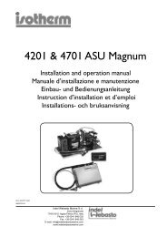
<strong>5301</strong> & <strong>5801</strong> ASU Magnum Twin<br />
Installation and operation manual
Operation and installation manual<br />
GENERAL<br />
<strong>Isotherm</strong> <strong>5301</strong>/<strong>5801</strong> ASU Magnum Twin is a<br />
seawater cooled refrigeration system for sailing<br />
yachts and motor cruisers. It is designed to<br />
generate low refrigeration temperatures also in<br />
the warmest conditions while at the same time<br />
consuming an absolute minimum of battery power.<br />
This is achieved by using our patented electronic<br />
control system ASU that runs the compressor at 75<br />
% higher speed when the boats engine is running.<br />
This in combination with a holding plate<br />
inside the refrigerator, stores the refrigeration<br />
energy produced for long periods.<br />
The following points are important, to achieve a good<br />
result:<br />
Refrigerator box<br />
To retain as much cold air as possible when opened, a toploading<br />
box is usually preferable to a side opening one.<br />
A most important factor in achieving good results is that the<br />
refrigeration box is well insulated. Do not use polystyrene<br />
type material. Expanded or cross-linked PVC or polyurethane<br />
insulation material should be used. Recommended<br />
insulation thickness (multiply by 3 for freezers): 30 mm<br />
for up to 50 litre boxes; 50 mm for up to 100 litres and<br />
75 – 100 mm for larger boxes. If space is available use<br />
thicker insulation around the lower part and in the bottom.<br />
A moveable partition should be installed in the box to allow the<br />
frozen food section surrounding the cold plate to be reduced to<br />
the smallest space possible so that the correct temperature of 4<br />
– 6°C (39 – 43°F) can easier be maintained in the refrigeration<br />
section. The lid must also be insulated but more important that<br />
it fits tightly into the opening. If a water drain is fitted in the<br />
bottom of the box, this must always be closed during use to<br />
avoid cold air from running out and warm damp air entering.<br />
Electrical system<br />
An electrical system that is both correctly dimensioned and in<br />
good working order is required. This is especially important if the<br />
refrigeration system is to operate continuously for a few days<br />
during warm weather and not have to start the engine for charging.<br />
Calculate the boats total power requirements. The engine<br />
should always have a separate battery for starting.<br />
In addition to the battery capacity required for other<br />
electrical equipment on board, one additional battery 100<br />
- 120 Ah will be sufficient for the refrigeration power supply.<br />
In addition to increasing the amount of ”standby” power available<br />
on board, the extra service battery can also store surplus<br />
power when the engine is generating this. Two batteries can,<br />
of course, accept twice the amount of charge. The alternator<br />
is normally not a limiting factor. All service batteries shall be<br />
connected to a ”battery bank” and must have generouslydimensioned<br />
cables for both positive and negative circuits if<br />
they are to receive full charging voltage from the alternator.<br />
Using the refrigerator<br />
Power consumption is dependant to a large degree on how<br />
the refrigerator is used.<br />
Let refrigerated food remain inside the fridge as far as<br />
possible and take them out only when required. Don’t<br />
leave them out of the fridge longer than absolutely<br />
necessary when cooking or having your meal. Put them<br />
back as quickly as possible. Avoid placing warm food in<br />
the fridge. If possible, use an insulated thermal bag when<br />
carrying frozen or chilled foodstuffs from home or the shop.<br />
Let the engine run for a while extra when leaving or<br />
approaching the harbour. The engine alternator will then supply<br />
an extra boost of refrigeration energy just when needed, i.e.<br />
immediately before non-power periods of sailing or in harbour.<br />
Refrigeration temperatures<br />
The correct temperatures for storing sensitive foodstuffs<br />
such as meat, fish, milk products etc, are as follows:<br />
The correct way to store refrigerated food is to never<br />
allow its temperature to exceed 6°C (43°F). Switching<br />
off the refrigerator overnight is a false economy and<br />
from a hygienic point in view it is not recommended.<br />
Internal temperature of refrigerated<br />
food<br />
Duration after which food can<br />
become unfit for consumption<br />
10°C (50°F) 1 day or less<br />
8°C (46°F) 1-2 days<br />
6°C (43°F) 2-3 days<br />
4°C (39°F) 5 days<br />
1°C (34°F) 5-7 days<br />
The correct way to store refrigerated food is to never<br />
allow its temperature to exceed 6°C (43°F). Switching<br />
off the refrigerator overnight is a false economy and<br />
from a hygienic point in view it is not recommended.<br />
Compressor unit – Fig. A<br />
The Danfoss BD50F dual volt 12/24 V refrigeration<br />
compressors are of the very latest design and produces<br />
extremely high refrigeration energy while consuming very little<br />
battery power. As it is driven by 3-phase alternating current, it<br />
has an unbeatable starting ability and the speed and capacity<br />
can be regulated. It is of the same totally hermetic design<br />
as that of domestic refrigerators and has a long operating<br />
lifetime, low noise level and is completely maintenance free.<br />
The piston type compressor operates on a mixture of<br />
refrigerant and oil. The compressor unit are to be mounted<br />
horizontally but it will operate at a continuous angle of<br />
heel up to 30° in all directions. Should this angle be<br />
exceeded, the compressor will stop automatically. It will<br />
re-start automatically when the angle has been reduced.<br />
The compressor unit is integral with the water-cooled<br />
condenser, which is equipped with a self priming water<br />
pump.The compressor unit is delivered pre-filled with<br />
refrigerant and has irreversible quick coupling connections<br />
on the ends of the flexible piping which connects it to<br />
the holding plate. These couplings can be disconnected<br />
and re-connected should either unit need re-positioning.
To simplify connecting up the system, the electronic<br />
control unit mounted on the side of the compressor is<br />
fitted with tab-type terminals for the positive and negative<br />
main power supply cables, modular connectors for<br />
the temperature sensors and the control panel cables.<br />
The modular connectors have different sizes to prevent<br />
incorrect connection. The electronic units contains microprocessors<br />
with programs for slow running, speeding<br />
up the compressor when the engine is running, battery<br />
monitoring for high and low voltage, automatic defrosting,<br />
water pump control, regulating the holding plate<br />
temperature, transmitting signals to the control panel etc.<br />
The compressors and the electronic units fulfil applicable<br />
radio interference regulations (EMC) and are CE-marked.<br />
When connected to shore power, a high quality marine<br />
battery charger of minimum 20A output should be used.<br />
The battery charger must always be connected to the<br />
batteries and never direct to the refrigeration system.<br />
Holding plate – Fig. B<br />
The holding plate is a hermetic, stainless steel container<br />
holding a special cooling medium, which freezes to ice<br />
when the engine is running. The freezing point of the liquid<br />
is normally –8°C (17°F). The holding plate is connected<br />
to the compressor unit by a pliable, 3 meter (~10 foot)<br />
long tinned copper pipe of 6 mm ( 1⁄4”) diameter fitted<br />
with quick coupling connectors. The holding plate must<br />
be fitted as high as possible in the refrigerator. It may be<br />
installed in any vertical or horizontal position required and<br />
at any level above or below that of the compressor unit.<br />
A temperature sensor is fitted to the rear of the holding plate. This<br />
is to be connected to the compressor unit by the cable and can<br />
suitably follow the same route as the connecting pipe. This pipe,<br />
together with the compressor unit and the holding plate, is prefilled<br />
with the correct amount of refrigerant and on no account<br />
should any attempt be made to either shorten or lengthen the<br />
pipe. If the pipe is too long, the excess should be made into<br />
a coil at some suitable position. If a longer pipe is required,<br />
pre-filled 1.5, 2 and 2.5 metre extension pipes are available.<br />
A 2.5 metre (8 ft.) extension for the temperature<br />
sensor cable is also available, Part no. SEB00038AA.<br />
Control panel – Fig. C<br />
The control panel is<br />
equipped with a three-way<br />
switch, green, yellow and<br />
red indicator lights and a<br />
rheostat for manual temperature<br />
setting when running<br />
on shore power or on solar<br />
panels. The system is<br />
off when the selector switch<br />
is in the middle position.<br />
Upper position is MAN.TEMP and lower position is<br />
NORMAL.AUTO.<br />
The control panel has a modular connector for the 4<br />
metre (13 ft.) control cable from the electronic unit.<br />
Should this require extending, use the 10 metre (33<br />
ft.) accessory control cable instead. Part no. 39230.<br />
The control panel is normally placed near the refrigerator.<br />
OPERATION<br />
The <strong>Isotherm</strong> ASU Magnum Twin can be operated<br />
in two ways. In NORMAL.AUTO or MAN.TEMP.<br />
When energy saving is needed, switch to NORMAL.AUTO<br />
working mode. Optimum refrigeration temperature<br />
is then automatically maintained while consuming<br />
the lowest amount of battery power possible.<br />
When there is no need of energy saving, switch to<br />
MAN.TEMP working mode. The automatic functions<br />
are now partially blocked and the refrigeration<br />
temperature can be manually adjusted. (Fig. C)<br />
By means of the three-way switch on the panel the refrigeration<br />
system is started, stopped and working modes are selected.<br />
Working mode is indicated on the indicator lights to the right<br />
of the switch. No indicator light on means the system is off.<br />
Operation in NORMAL.AUTO<br />
The green light indicates that power is being<br />
supplied and the refrigeration system is on.<br />
When the engine is running and the voltage supply is over<br />
13.2 (26.4) volt (measured on the compressors control unit),<br />
the compressor starts to supply cooling energy to the holding<br />
plate. It starts within the first 30 seconds and operates first at<br />
low speed with the yellow indicator light ”Economy” on and<br />
after half a minute, the speed of the compressor increases<br />
by 75% and the red indicator light ”Freeze” comes on instead<br />
of the yellow. This operating condition is maintained until the<br />
holding plate is completely frozen at approx. –14°C (7°F).<br />
This can take between 45 minutes and 2 hours depending on<br />
box size, box insulation and ambient temperature. On reaching<br />
this temperature, the compressor stops and the red light goes<br />
out and only the green will remain on. When the temperature<br />
of the holding plate rises to –10°C (14°F), the compressor<br />
restarts to charge the holding plate and the red light comes<br />
on again. This process is repeated a couple of times every<br />
hour keeping the holding plate at its optimum efficiency level.<br />
When the engine is stopped, the compressor also stops<br />
shortly afterwards when the battery voltage has gone<br />
down to 12.7 (25.4) volt. The surplus of refrigeration<br />
energy stored in the holding plate is now used first. Only<br />
when this has been consumed does the compressor start<br />
again. The yellow light indicates that it is now running, in<br />
the firs hand, at its low ”Economy” speed to top-up the<br />
holding plate only. This working condition starts when the<br />
temperature of the holding plate rises to -1°C (30°F) and<br />
stops when it reaches the economy level of -6° (21°F).<br />
Operation in MAN.TEMP<br />
This position can be used either when shore power or solar<br />
panels are being used or when energy saving is not required<br />
and a higher or a lower refrigeration temperature is desired for<br />
some reason. The automatic function is partially blocked and the<br />
temperature can be set manually on the rheostat – clockwise for<br />
colder and anti-clockwise for warmer. ”A” indicates the holding<br />
plate temperature point for ”Accumulation”, abt. –8° (46°F).<br />
In the MAN.TEMP working mode, the compressor starts and<br />
runs in the first hand in low speed to maintain the temperature<br />
level selected. If the difference between chosen and real<br />
temperature is more than 6°C, the compressor will automatically<br />
speed up for faster cooling down. As soon as this extra power<br />
is not needed, the compressor speed will be reduced for<br />
lowest power consumption and to keep selected temperature.<br />
2
Indicator lights<br />
Green<br />
Geen+ yellow<br />
Green + red<br />
Green +<br />
yellow + red<br />
Flashing yellow<br />
+ red<br />
Flashing<br />
yellow<br />
Power and system on, the compressor is<br />
stand-still due to sufficiently low temperature<br />
of the holding plate.<br />
Compressor running within the higher<br />
temperature range.<br />
Copressor running within the lower temperature<br />
range.<br />
Compressor running at lowest possible<br />
speed to reach selected temperature in<br />
MAN.TEMP working mode.<br />
Error signal from the elctronic unit. Automatic<br />
re-start after 1 minute.<br />
Low battery voltage sensor has stopped<br />
the compressor. Automatic re-start occurs<br />
when engine is started to charge batteries<br />
again.<br />
Note: The compressor will start 30 seconds after switching<br />
on. When the engine is started, 1⁄2 to 10 minutes are required,<br />
depending on the boats charging equipment and battery<br />
condition, before the system reacts. When the engine is<br />
stopped, 1⁄2 to 5 minutes are required, depending on battery<br />
condition and level of charge, before the system reacts.<br />
Automatic de-frost<br />
Defrosting will take place automatically every tenth<br />
day of operation. If so preferred, the de-frosting can<br />
be avoided by means of switching off the system<br />
for a minute. The timer will than start from 0 again.<br />
Water pump system<br />
The water pump power supply is connected to a voltage<br />
reducer unit for flow regulation to give enough cooling<br />
with lowest possible power consumption and noise level.<br />
Maintenance is limited to a periodically, at least once<br />
a year, check and when so is needed exchange of the<br />
zinc anode placed in the outgoing water Tee connector.<br />
It is also recommended to exchange the pump valve kit once<br />
every second year. As the valve material ages the seals will<br />
no longer perform.<br />
Clean also periodically the water filter, interval depending on<br />
the water quality.<br />
Drain the water system, including the pump and filter, if<br />
temperatures below freezing point are expected, or fill up<br />
properly with anti-freeze.<br />
Maintenance<br />
If the quick couplings have been tightened correctly during<br />
installation, the totally hermetic system will not require refilling<br />
of refrigerant. Maintenance is limited to removing dust<br />
and dirt from the compressor and condenser unit, regular<br />
check-up and re-placement of the zinc anode, cleaning<br />
water filters, defrosting the holding plate when required and<br />
keeping the box inside dry and clean to prevent bad air.<br />
It is of vital importance that the batteries and the charging<br />
system are kept in good condition.<br />
The complete system should remain on board during the<br />
winter, but it may not always be able to be started at ambient<br />
temperatures below freezing.<br />
Safety<br />
For your own and others safety, please read this first.<br />
When connected to shore power, ensure that the power<br />
supply is equipped with an earth leak switch. Danger!<br />
A battery charger must be connected to the battery, never<br />
direct to the refrigeration system.<br />
In addition to acid, a newly charged battery contains<br />
explosive gas. Danger!<br />
Never touch bare electric wiring or contacts connected to the<br />
mains supply. Danger!<br />
Never open the refrigerant circuit except by the quickcouplings,<br />
which are of self-sealing type and designed for this<br />
purpose.<br />
The refrigeration unit must be disposed by a refrigeration<br />
specialist for correct recycling of components and care taking<br />
of the refrigerant.<br />
Technical data<br />
Type designation: <strong>5301</strong>, <strong>5801</strong><br />
Capacity <strong>5301</strong>: Holding plate 355x280x90 mm (14x11x3.5 inches) suitable for refrigeration boxes up to 260<br />
litres (9.2 cu.ft.)<br />
Capacity <strong>5801</strong>:<br />
Compressors:<br />
Voltage:<br />
Low voltage protection:<br />
Current consumption:<br />
Holding plate 400x320x90 mm (15.7x12.6x3.5 inches) suitable for refrigeration boxes up to<br />
325 litres (12 cu.ft.)<br />
Danfoss BD50F (x2)<br />
12/24 volt<br />
Cut out at 10/21 volt. Automatic re-set when voltage has been above 12/24 volt for more than<br />
30 sec.<br />
Low speed approx 7A (12 volt)<br />
High speed approx. 10A (12 volt)<br />
Stand-by (green LED on) 50 mA (12 volt)<br />
System switched off 32 mA (12 volt)<br />
Fuse: 12 volt: 20A, 24 volt 10A type car blade fuse (DIN 75281/SAE J 1284)<br />
Refrigerant:<br />
R134a, 210 gram<br />
Water pump: Flow: 3 l/min (0.6 GPM) Maximum suction height: 2 m (6.5 ft) Current consumption: 0.6A<br />
Dimensions:<br />
Weight:<br />
Compressor unit 475x225x175 mm (18.7x8.9x6.9 inches)<br />
Holding plate, see above.<br />
<strong>5301</strong>: 27 kgs (591⁄2 lbs)<br />
<strong>5801</strong>: 30 kgs (66 lbs)<br />
Specifications are subjet to change without prior notice.<br />
3
Fault finding chart<br />
Fault Possible cause Action<br />
Nothing happens when switched<br />
on. All lights off.<br />
No power supply. Reversed polarity.<br />
Is main power switched on<br />
Check fuse.<br />
Green light on. Compressor does<br />
not start.<br />
Yellow light flashing. Low voltage<br />
cut out.<br />
Yellow and red light flashing.<br />
Overload sensor cut-out.<br />
Holding plate cold enough.<br />
Temperature sensor not connected.<br />
Fault in electronic unit.<br />
Battery in pour condition. Voltage drop due to bad<br />
cables.<br />
Ambient temperature too low, < 5°C.<br />
Faulty water pump, clogged water inlet.<br />
Faulty black electronic unit.<br />
No action required.<br />
Check cable and connections.<br />
Exchange. *<br />
Inspect charging circuit. Measure voltage drop<br />
when running and replace cables and terminals if<br />
required. Switch off, wait 5 sec. and re-start.<br />
Restarts after 1 min.<br />
Compressor too hot, check water pump, filter and<br />
hoses.<br />
Exchange electronic unit. *<br />
Green light on, red switching onoff.<br />
Compressor runs but no<br />
refrigeration generated.<br />
Compressor runs often but<br />
temperature in box not cold<br />
enough.<br />
Compressor running and too cold<br />
in the box.<br />
Compressor never stops running:<br />
-Not cold enough.<br />
-Too cold.<br />
-Temp cannot be reduced on<br />
MAN.TEMP.<br />
Compressor keeps running when<br />
engine is stopped.<br />
Shore power battery charger that cannot<br />
compensate for higher power consumption when<br />
compressor speeds up.<br />
Loss of refrigerant. Connections not tight enough.<br />
Poor insulation. Open box bottom drainage.<br />
Too much gas in the system.<br />
Water condenser not cooling correctly.<br />
Battery charger or solar panel keeping voltage on<br />
high level, above 13.2 volt.<br />
See above.<br />
Temp sensor faulty.<br />
Temp sensor touching box wall or ice build-up.<br />
Batteries in excellent condition or extra power<br />
source like solar panel or wind generator.<br />
After three attempts within 7 min. compressor<br />
automatically locks on lower speed and<br />
intermediate temperature range.<br />
Inspect and tighten. Contact specialist to fill<br />
refrigerant. *<br />
Re-insulate. Close drainage.<br />
Improve water flow to the pump.<br />
Specialist to check gas pressure an adjust<br />
quantity. *<br />
Switch over to MAN.TEMP.<br />
See above.<br />
Exchange temp sensor.<br />
Adjust sensor mounting and de-frost.<br />
Normal operation. If temp. becomes too cold,<br />
switch over to MAN.TEMP.<br />
Compressor will not run on full<br />
speed, red light, when engine is<br />
running.<br />
Radio interference when<br />
compressor runs.<br />
Fuse blows.<br />
Poor charging. Voltage drop. Power supply cables<br />
too thin. Connections affected by verdigris. Loose<br />
fuse.<br />
System is suppressed and fulfils present EMC<br />
directives.<br />
Fault in the electronic unit.<br />
Check charging system, cables, fuses, terminals<br />
and rectify.<br />
Clean and grease.Mount power cables as<br />
separate as possible from radio equipment.<br />
Improve and separate earth connections on radio<br />
equipment.<br />
Fit additional suppresser.<br />
(Part no. SED 00002 BA)<br />
Renew electronic unit *<br />
and fuse.<br />
If a complicated fault does occur, such as those requiring specialist assistance please contact for service and technical support:<br />
Indel Marine USA<br />
Thermoprodukter AB, Sweden<br />
Phone: +1 954 772 8355 Phone: +46 480 425 880<br />
Fax: +1 954 772 3 839 Fax: +46 480 127 75<br />
E-mail: info@indelmarineusa.com<br />
E-mail: info@isotherm.com<br />
4
INSTALLATION<br />
Tools required:<br />
In addition to the usual basic hand tools such as<br />
screwdrivers, hammer, pliers, assortment of<br />
drills, saw, tape measure etc. the following are required:<br />
Small electrical drilling machine, a 30 mm (11⁄4”)<br />
hole saw, 21 and 24 mm fixed spanners, crimping<br />
pliers for electrical spade type cable connectors.<br />
A sufficient length of cables of suitable diameter<br />
for connecting the compressor unit to the<br />
battery and an assortment of screws to attach<br />
the various components are also required.<br />
General<br />
First, decide where the various components are best<br />
situated. Choose a suitable place for the compressor unit at<br />
a pipe-run distance of less than 3 m (91⁄2 ft) from the holding<br />
plate in the refrigeration box. Try to find a position that<br />
requires only gentle, wide radius bends of the pipework. The<br />
space intended for the compressor unit should preferably be<br />
cool and large and able to be reached by the cables from the<br />
battery.<br />
The compressor unit together with its electronics is designed<br />
to withstand a normal marine environment. It can be fitted<br />
in a splash-free position but should preferably be placed in<br />
as dry surroundings as possible. Mount the compressor unit<br />
in a horizontal position to allow it to achieve its maximum<br />
permitted 30° angle of heel.<br />
The holding plate position in the box should be planned with<br />
consideration being taken to the partition, routing of piping,<br />
etc. The unit may be fitted in any desired position but must be<br />
as high as possible in the box.<br />
Fitting the holding plate<br />
If the box to be used is already in place, inspect it to<br />
establish the quality of its insulation, as this is an important<br />
thermal efficiency factor. The best insulation materials are<br />
polyurethane foam; Bonocell or any other cross-linked<br />
expanded polyurethane foam. A good rule-of-thumb is that<br />
the thickness of this material should be 0.5 – 1 mm (1/32” w<br />
3/64”) per litre (1/4 gallon) of the box.<br />
The holding plate can be placed in any position. It can be<br />
fitted vertically, horizontally, upright or hanging. Due to the<br />
fact that cold air always falls downward the holding plate<br />
should be placed as high up in the box as possible.<br />
The 6 mm (1⁄4”) tinned copper pipe leading from the holding<br />
plate can be easily bent allowing it to leave the box in any<br />
direction.<br />
The best position for the pipe to exit the box is behind the<br />
holding plate in the space formed by the angle supports of<br />
the holding plate. The pipe should be handled with care and<br />
bent gradually to avoid creasing it. Form it around a suitable<br />
cylindrical object if sharp bends are required.<br />
Be particularly careful with the thin capillary tube and its<br />
connection at the opposite end and don’t loosen its two<br />
locking turns around the thicker pipe. The pipes are pre-filled<br />
with refrigerant and must not be cut.<br />
Start installation by unrolling the pipe to its full extent.<br />
Installation of the holding plate is easier if someone can<br />
assist. One person can hold the plate and direct the pipe<br />
through the side of the box while the other feeds the pipe<br />
together with the two connections through the box wall,<br />
bulkheads, etc. The holding plate can be screwed either onto<br />
the wall or on the underside of the top if space is available. If<br />
necessary, it may be easier to mount if openings are cut into<br />
the holes in the two supports under the holding plate to suit<br />
the diameter of the screws to be used.<br />
These screws may than be fitted into the box first and the<br />
holding plate ”slotted” into place.<br />
Drill the 30 mm (11⁄4”) hole for the pipe and connections as<br />
high as possible. This is where it is warmest should any<br />
leakage of air occur.<br />
Mount the temperature sensor cable together with the<br />
connection pipe through the hole in the box wall. Fill the<br />
hole surrounding the pipe and sensor cable with insulation<br />
material. Any excess piping should be coiled in a suitable<br />
position outside the box and securely fastened to avoid<br />
vibrating.<br />
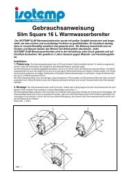
Partition for adjusting box temperature – Fig. I<br />
Cold air from the holding plate sinks down to the bottom<br />
of the box. The box, therefore, needs a separate space to<br />
enable part of it to be used as a freezer compartment. To<br />
achieve best results this compartment should be no larger<br />
than absolutely necessary. The partition should be a tight fit<br />
against the box sides and reach a height of approximately 5<br />
cm (2”) below the top edge of the holding plate.<br />
It should be able to be adjusted vertically 0 – 2 mm (0<br />
– 3/32”) to create a gap at the bottom to allow a suitable<br />
amount of cold air to flow from the freezer section into the<br />
refrigeration section to maintain a temperature of + 4° to +<br />
6°C (39 – 43°F). The partition should not be insulated, be<br />
easy to clean and preferably made in transparent plexiglass.<br />
Kylmagasin<br />
Holding plate<br />
Kältespeicher<br />
Plaque réfrégerante<br />
Mellanvägg<br />
Partition<br />
Zwischenwand<br />
Cloison<br />
Fig. I<br />
5
Compressor unit<br />
Water out<br />
Water in<br />
This reduces the speed of the pump and the amount of water<br />
flowing through it.<br />
After installation, if the cooling water has difficulty in<br />
circulation, when the pump is dry or after if the system<br />
has been drained, push the button (A) for a maximum of 2<br />
minutes. The voltage reduction is then by-passed and the<br />
will run at full speed (Fig. G). The voltage reducer gives a<br />
constant 5 volt output to the pump independent of the level<br />
of the voltage supplied to the voltage reducer (10 – 40 volt).<br />
Recommended water filters: Shurflo 252-3300, Flojet<br />
1740-002, Jabsco-Rule 36400-0000, Whale FV2060.<br />
Zincanode<br />
INLET 10-40 VOLT<br />
Brown=positive + (Fan)<br />
Black="F"<br />
Blue=negative -<br />
MAGNUM<br />
VOLTAGE REDUCER<br />
Water out<br />
Water in<br />
Fig. G<br />
PUSH BUTTON<br />
(Start up/winter drain)<br />
Max 2 minutes<br />
A<br />
OUTLET 5(9) VOLT<br />
1=Pump positive + (red)<br />
2=Pump negative - (blue)<br />
3=TWIN Compr. II "C"<br />
4=TWIN Compr. II "T"<br />
The compressor unit should be fitted in a horizontal<br />
position in a suitable place. If it is positioned in a stowage<br />
place a guard may be required for protection. The unit<br />
will operate continuously at angels of up to approx. 30°.<br />
The unit should be screwed down well using all<br />
fastening holes in the bottom plate to withstand<br />
all kind of rough seas and healing angles.<br />
Installation can often be simplified if the quick coupling<br />
connections on the piping and the compressor unit are screwed<br />
up tight before the compressor unit is finally tightened down in<br />
position. Do not remove the protective caps from the couplings<br />
until immediately before that are about to be done and save<br />
them for possible future use. The quick coupling connections<br />
can be turned by hand to the bottom before continuing<br />
tightening steadily and quickly with spanners. While tightening<br />
it is important that the male part of the connection stationary is<br />
held with a 21 mm spanner so that it does not rotate and damage<br />
the thin capillary tube (See fig. D). Tighten the couplings up<br />
hard. Use fixed spanners 21 and 24 mm for the couplings.<br />
Fig. D<br />
Sea water connections<br />
The water inlet on the water cooled condenser must be<br />
connected to a through-hull fitting that will ensure that<br />
cooling water can be fed to the water pump even when<br />
sailing. Mount a water filter on the water inlet. Use an<br />
easy-to-clean type with a large fine mesh cartridge. The<br />
outlet can be connected to an existing through hull fitting<br />
such as the drain for the sink if this always is kept open.<br />
Best solution is to mount also a separate outlet fitting to<br />
always be sure there is a free water flow for the cooling circuit.<br />
If the water flow is interrupted the refrigeration unit<br />
will stop after a wile and indicate a malfunction.<br />
The compressor unit can be installed up to 2 m (61⁄2 ft.) above<br />
the water level. To achieve a near-silent operation, a voltage<br />
reducer is fitted to the power supply to the water pump.<br />
Control panel<br />
The control panel should be positioned where it can be<br />
easily seen and within reach of the 4 m (13 ft.) cable from<br />
the electronic unit on the compressor. Thehousing can be<br />
mounted using the accompanying long screws. A 12 mm (1⁄2”)<br />
hole should be drilled for the cable behind the panel. The panel<br />
can also be let into its surrounding by removing the plastic<br />
housing and attaching it with the accompanying screws.<br />
Fig. C<br />
Electrical wiring<br />
Run a positive lead from the + terminal of the battery or the<br />
battery main switch across the accompanying 20 A fuse in a<br />
12 volt system (alternatively 10 A in a 24 volt system) and a<br />
negative lead from the – battery terminal.<br />
Connect the power leads to their tab-type terminals on the<br />
electronic unit. Be sure not mixing up plus and minus. Minus<br />
is above the plus terminal on the red electronic unit.<br />
A spark occurs when the power leads are connected. This<br />
is because the electronic units contain capacitors, which are<br />
then charged.<br />
Avoid connection of the power cables through switches on a<br />
separate switch panel if they are not designed for at least 25<br />
A load.<br />
A battery charger must never be connected directly to the<br />
refrigeration system without having a battery connected in<br />
parallel.<br />
Use cables of sufficient cross sections, see table below:<br />
Cable area<br />
mm²<br />
Gauge<br />
MAN.TEMP<br />
A NORMAL.AUTO<br />
ECONOMY FREEZE<br />
Max. cable<br />
length m/ft. 12V<br />
ASU<br />
Automatic Start Up<br />
Max cable length<br />
m/Ft. 24V<br />
2.5 12 2.5/8 5/16<br />
4.0 10 4/13 8/26<br />
6.0 10 6/19 12/38<br />
10.0 8 10/33 20/66<br />
Connect the temperature sensor cable from the holding plate<br />
in the box to the electronic unit in the upper modular connector.<br />
The control cable from the control panel is connected in the<br />
lower modular connector on the electronic unit. (Fig. G)<br />
6
Test run<br />
Start the refrigeration unit by selecting NORMAL.AUTO<br />
working mode. The green indicator light comes on<br />
immediately and the yellow one shortly after indicating that<br />
the compressor is running on low speed. Shortly after, a slight<br />
hissing sound can be heard from the holding plate, which<br />
after 15 – 30 minutes will show signs of moisture or frost.<br />
Start the engine. Within 1-10 minutes, depending on conditions<br />
of the batteries and alternator, the yellow light will go out and<br />
the red light will come on and the compressor is speeding up.<br />
When the engine is stopped, the voltage in the electrical<br />
system drops, within a few minutes the yellow light comes on,<br />
the red goes out and the speed of the compressor is reduced.<br />
If the holding plate has reached its full refrigeration capacity,<br />
however, the compressor will stop instead. There is always a 30<br />
second delay before the electronic monitoring system takes over.<br />
Finally, check that the electrical wiring and<br />
pipework are safe and securely fastened.<br />
Check also all water connections, hose clamps and adaptors.<br />
Wiring Diagram, fig. G<br />
2<br />
7<br />
1<br />
-<br />
+<br />
+<br />
Black<br />
Red<br />
5<br />
Black<br />
Red<br />
Blue<br />
F<br />
D<br />
C<br />
P<br />
T<br />
10<br />
Ohm<br />
Blue<br />
Brown<br />
4<br />
+<br />
3<br />
-<br />
A<br />
MAN.TEMP<br />
NORMAL AUTO<br />
isotherm<br />
ECONOMY FREEZE<br />
ASU<br />
6<br />
isotherm<br />
Brown<br />
Black<br />
-<br />
isotherm MAGNUM<br />
VOLTAGE REDUCER<br />
OUTLET 5(9) VOLT<br />
Red<br />
Black<br />
M<br />
8<br />
PUSH BUTTON<br />
1-Red pump +<br />
2-Black pump -<br />
3- Brown to "C"<br />
4-Blue to "T"<br />
+<br />
000843<br />
Fig. G<br />
1. Electronic unit ASU (blue housing)<br />
2. Electronic unit 12/24 volt<br />
3. Battery<br />
4. Fuse 20A-12V / 10A-24V<br />
5. ASU control panel<br />
6. Control cable<br />
7. Temperature sensor<br />
8. Voltage reducer<br />
9. Water pump<br />
10. Resistor, compressor speed setting<br />
7<br />
For service and technical support:<br />
Indel Marine USA<br />
Phone +1 954 772 8355<br />
Fax +1 954 772 8355 E-mail: info@indelmarineusa.com<br />
IT-61019 S. Agata Feltria (PU) - Italy<br />
Phone +39 0541 848030 Fax +39 0541 848563<br />
info@indelmarine.com www.indelmarine.com<br />
Thermoprodukter AB, Sweden<br />
Phone +46 480 425 880<br />
fax +46 480 127 75<br />
E-mail: info@isotherm.com