Isotemp Slim B 2004 - Isotherm
Isotemp Slim B 2004 - Isotherm
Isotemp Slim B 2004 - Isotherm

You also want an ePaper? Increase the reach of your titles
YUMPU automatically turns print PDFs into web optimized ePapers that Google loves.
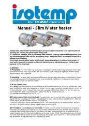
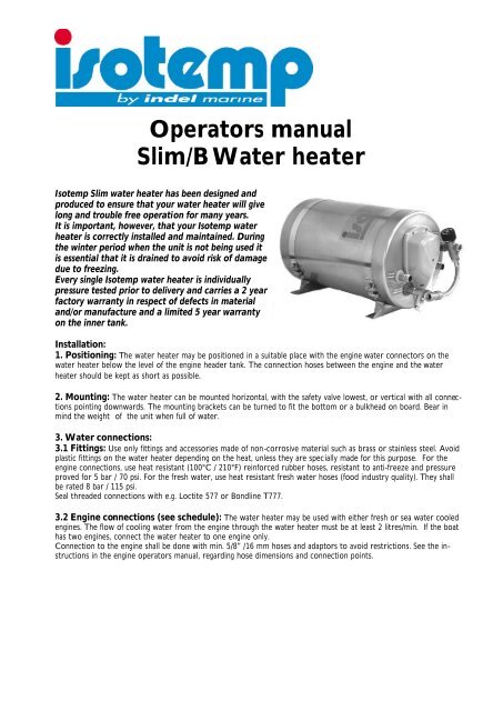
Operators manual<strong>Slim</strong>/B Water heater<strong>Isotemp</strong> <strong>Slim</strong> water heater has been designed andproduced to ensure that your water heater will givelong and trouble free operation for many years.It is important, however, that your <strong>Isotemp</strong> waterheater is correctly installed and maintained. Duringthe winter period when the unit is not being used itis essential that it is drained to avoid risk of damagedue to freezing.Every single <strong>Isotemp</strong> water heater is individuallypressure tested prior to delivery and carries a 2 yearfactory warranty in respect of defects in materialand/or manufacture and a limited 5 year warrantyon the inner tank.Installation:1. Positioning: The water heater may be positioned in a suitable place with the engine water connectors on thewater heater below the level of the engine header tank. The connection hoses between the engine and the waterheater should be kept as short as possible.2. Mounting: The water heater can be mounted horizontal, with the safety valve lowest, or vertical with all connectionspointing downwards. The mounting brackets can be turned to fit the bottom or a bulkhead on board. Bear inmind the weight of the unit when full of water.3. Water connections:3.1 Fittings: Use only fittings and accessories made of non-corrosive material such as brass or stainless steel. Avoidplastic fittings on the water heater depending on the heat, unless they are specially made for this purpose. For theengine connections, use heat resistant (100°C / 210°F) reinforced rubber hoses, resistant to anti-freeze and pressureproved for 5 bar / 70 psi. For the fresh water, use heat resistant fresh water hoses (food industry quality). They shallbe rated 8 bar / 115 psi.Seal threaded connections with e.g. Loctite 577 or Bondline T777.3.2 Engine connections (see schedule): The water heater may be used with either fresh or sea water cooledengines. The flow of cooling water from the engine through the water heater must be at least 2 litres/min. If the boathas two engines, connect the water heater to one engine only.Connection to the engine shall be done with min. 5/8” /16 mm hoses and adaptors to avoid restrictions. See the instructionsin the engine operators manual, regarding hose dimensions and connection points.
3.3 Freshwater connections (see schedule): The water heater is fed with fresh water from the electricalfresh water pump. Max working pressure for the pump: 3 bar / 42 psi. Fresh water is taken in at the safety valveTee. The hot water outlet, which also vents the water heater, should be connected to a mixer tap at the sink and/or basin outlet. Cold water can be mixed with hot to avoid scalding. Set a proper temperature on the thermostatmixing valve on the water heater. The temperature of the hot water can be set between 38 and 65 °C / 100 and150°F.A possible waste water hose (i.d. 10 mm / 3/8”) must always have a free outlet. There must be no valves or skinfittings, fitted to the waste water hose. A small quantity of water may be expended via the safety valve during theheating up period.3:4 Electrical connection: All internal connections are made in the factory. The power supply cable is fittedwith an standard EU plug, which should be fitted to a correctly installed socket. This socket as all ”high-voltage”installations on board, must be carried out to fulfil valid regulations. The <strong>Isotemp</strong> <strong>Slim</strong> water heater is designed tomeet regulations in this field.Important! The water heater shall be connected to the mains power supply only when it is in service.When leaving the boat for any length of a period, it is recommended to pull out the cable connectorfrom the socket to also disconnect the earth protection. This should be done even if the shore powersystem is shut off, as there can be a potential difference, between the earth from shore and the seawater earth of the boat. This can seriously damage, by stray current corrosion, the immersionheater, water heater tank or the engine with its drive unit.Installation of a insulation transformer in the shore power equipment eliminates the risk of galvaniccorrosion via the shore power connection.4. Start up/Test: Start the engine and check the circulation of the cooling water. Secure the hoses after checking.When using with a fresh water engine cooling system, compensate with anti-freeze for the additional volume inhoses and heat exchanger. Fill up the water heater with fresh water by starting the fresh water pump, leaving thehot water tap open to air the system. Check there are no water leaks and finally connect the power cable firstwhen the water heater is full. Check that the safety valve outlet is free to allow water to escape.Note: the water expands during the heat up process, a small quantity can come out through the safety valve.5. Maintenance:5:1 Winter drain: When there is a risk of freezing temperatures, the water heater must be drained. This isdone by pulling the lever on the safety valve to its open position. Take off the hot water hose and/or open the airbleeder screw on the mixer valve, to allow air coming into the tank.The water heater can be left safely on board over winter.5:2 Immersion heater: The immersion heater is 230V-750W. The thermostat equipment has an integratedworking thermostat and a double overheat protection thermostat. This is manually re-settable, by pushing thewhite pin at the top of the thermostat. Also check why the overheat thermostat initially tripped before reconnectionthe power supply.When leaving the boat for shorter or longer periods, it is recommended to disconnect the power supply cableplug. See above at 3:4.5:3 Controls: Check regularly that there is no leakage in the connections.
Technical data <strong>Isotemp</strong> <strong>Slim</strong>/BType Volume ltr. L x øD mm Weight kg. Immersion heater601521S000003 15 540 x 285 8 230V / 750W602021S000003 20 665 x 285 9.5 230V / 750W602521S000003 25 785 x 285 11 230V / 750WConnection fresh water: BSP ½” outside for cold and hot water, Engine water: BSP ½” outside.Inside thread for cold water in when thermostat mixing valve is mounted.Material: Engine water coil, storage tank and all connections: Stainless steel AISI 316Outside cover and mounting feet stainless steel AISI 304Immersion heater in copper covered by nickel. Immersion heater also available in 120V version.Safety valve: 85 psi / 6.0 barInsulation: Foamed expanded polyurethaneAbove data valid for <strong>Slim</strong>/B with thermostat mixing valve mounted.Changes of the specification may be done without prior notice.DimensionsType A L B TL W H15L 160 320 245 540 285 29520L 160 445 245 665 285 29525L 160 570 245 785 285 295I-61019 S Agata Feltria (PU)ItalyPhone +390541848030Fax +390541848563info@indelmarine.comwww.isotherm.com
Principal connection diagramEngineEnginecoolantWater tapHot water outCold water inPressure water pumpSafety valveFresh water tankWiring diagramOver heat protection Thermostat Heating elementLNBrownBlueYellow-green
ThermostatsOver heat protectionthermostat, re-set buttonon the top to press forre-setting.Working thermostat167 °FFRESH WARMWATER OUTUSCITA AQUACALDAENGINE WATERACQUA MOTOREENGINE WATERACQUA MOTOREFRESH COLD WATER ININGRESSO ACQUA FREDDA++Safety valve 85 Psi/6.0 barwith drain valve.Exchange of heater coilExchange of heater coilENGINE WATERACQUA MOTOREFRESH COLD WATER ININGRESSO ACQUA FREDDA++FRESH WARMWATER OUTUSCITA AQUACALDAENGINE WATERACQUA MOTORESwitch off the mains power, pull out the mainspower cable. Take off the plastic cover, unscrewthe two screws at the sides, push the cover slightlydownwards and the cover is free to take off.Unscrew the thermostat and the overheatprotection from their brackets for better access.Take off the electrical wires from the heater coil.Loosen the center nut and unscrew it completetly,the bracket and the heater coil are now loose.Put on the nut on the heater coil center bolt(without the bracket mounted), it is easier to gripthe unit with the nut on the center bolt.Push off the rubber seal, let it fall in, it will comeout together with the heater coil unit.Turn the heater coil 90° to the left, the wireconnection tabs shall point to the right. Twist theunit so its inner end hits the tank wall on the left side.Pull out the heater coil unit through the hole with theleft side first.Unscrew the heater coil from the big mounting flange.Use wrench size 19 mm.Mount the new heater coil with the new enclosedwashers. The inner end shall piont downwards whenit is mounted in correct positon.Assembly in the opposite order to the descriptionabove.Remember, put on the big rubber seal first.