

On-Chip Inductance Modeling and RLC Extraction of VLSI - Stanford ...
On-Chip Inductance Modeling and RLC Extraction of VLSI - Stanford ...
On-Chip Inductance Modeling and RLC Extraction of VLSI - Stanford ...

Create successful ePaper yourself
Turn your PDF publications into a flip-book with our unique Google optimized e-Paper software.
B. Mutual <strong>Inductance</strong> <strong>of</strong> Two Parallel Wires with Unequal<br />
Length.<br />
To calculate wire inductance in a complex wire environment<br />
or self inductance consisting <strong>of</strong> several cascaded segments<br />
in sequence, mutual inductance formulae <strong>of</strong> two<br />
parallel wires with unequal length are derived. There are six<br />
different positions <strong>of</strong> two parallel wires which result in six<br />
mutual inductance formulae. Fig. 5 illustrates the six different<br />
cases. l, m, p, q <strong>and</strong> s represent the wire lengths <strong>and</strong> some<br />
wire overlap lengths. d is the wires distance.<br />
l<br />
d<br />
d<br />
p<br />
m<br />
s<br />
Case 1<br />
Case 3<br />
l<br />
m<br />
d<br />
l<br />
m<br />
q<br />
l<br />
d<br />
Fig. 5 Six relative positions for mutual inductance.<br />
If the wave length <strong>of</strong> the signal at frequencies <strong>of</strong> interest is<br />
much larger than the dimension <strong>of</strong> the wire, the magnetic<br />
induction at every point <strong>of</strong> the field is in phase with the current.<br />
The induced electromotive forces are at all points in<br />
phase. The magnetic flux linked with a wire may be considered<br />
as the resultant <strong>of</strong> the fluxes (which is in phase under<br />
quasi-stationary condition) contributed by the separate elements<br />
<strong>of</strong> the inducing circuit. That is, the mutual inductance<br />
<strong>of</strong> a wire with the inducing wires is the algebraic sum <strong>of</strong> the<br />
mutual inductances <strong>of</strong> the separate elements <strong>of</strong> the inducing<br />
wires. For example, the mutual inductance <strong>of</strong> the two wires in<br />
the case 3 can be calculated as,<br />
M =<br />
1 2 -- [( M m+ p + M m + q ) – ( M p + M q )]<br />
where M m+p represents the mutual inductance <strong>of</strong> the two<br />
parallel wires with m+p equal length <strong>and</strong> separation <strong>of</strong> d. So<br />
are the other mutual terms.<br />
Six formulae like (3) can be obtained <strong>and</strong> six formulae can<br />
be derived based on (2). For example, for Case 4, it can be<br />
shown as,<br />
M 1 µ 0<br />
(4)<br />
2 -- ----- l ⎛ l<br />
----------- ⎞<br />
⎛4m( l–<br />
m)<br />
⎞<br />
= ln + mln<br />
2π ⎝l<br />
– m⎠<br />
⎜------------------------<br />
d 2 ⎟ – 2m + d<br />
⎝ ⎠<br />
where l, m <strong>and</strong> d are as indicated in Fig. 5.<br />
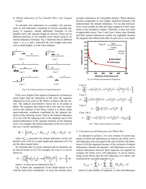
Fig. 6 shows the comparison <strong>of</strong> the model based on (4)<br />
with the field solver simulations. As seen, the formula gives<br />
d<br />
m<br />
m<br />
s<br />
Case 2<br />
l<br />
m<br />
Case 4<br />
Case 5 Case 6<br />
s<br />
l<br />
(3)<br />
accurate estimations for reasonable distance. When distance<br />
become comparable to wire length, analytical formulae will<br />
underestimate the mutual inductance. For on-chip interconnects,<br />
wires usually are thin <strong>and</strong> long compared to their separation<br />
in the simulation window. Therefore, it does not result<br />
in appreciable errors. Case 1 <strong>and</strong> Case 6 share same formula<br />
<strong>and</strong> their mutual inductances usually are negligible because<br />
the magnetic flux linked each other in each case is very small.<br />
<strong>Inductance</strong> (nH)<br />
0.8<br />
0.7<br />
0.6<br />
0.5<br />
0.4<br />
0.3<br />
0.2<br />
0.1<br />
Case 4:<br />
1mm<br />
0.5mm<br />
w=5 µm<br />
t=1 µm<br />
Simulation<br />
Formula<br />
0<br />
0 100 200 300 400 500<br />
Distance <strong>of</strong> the lines (µm)<br />
Fig. 6 Formula <strong>and</strong> simulation comparison.<br />
Case 2:<br />
u 0 l + m – s<br />
M ----- ( l – s)<br />
⎛-------------------<br />
⎞ ( l + m–<br />
s)<br />
⎛4s( m–<br />
s)<br />
⎞<br />
= ln + m ln------------------------<br />
+ s ln ----------------------<br />
4π ⎝ l – s ⎠<br />
⎜<br />
m–<br />
s ⎝ d 2 ⎟ – 2s<br />
⎠<br />
Case 3:<br />
u 0<br />
M ----- m 4( m + p)<br />
( m+<br />
q)<br />
( m + p)<br />
( m+<br />
q)<br />
= ln----------------------------------------<br />
4π<br />
d 2 + p ln------------------<br />
+ q ln-----------------<br />
– 2m<br />
p<br />
q<br />
Case 5:<br />
u 0<br />
M ----- l ⎛l<br />
+ m<br />
-----------⎞<br />
( l + m)<br />
= ln + m ln----------------<br />
– d<br />
4π ⎝ l ⎠ m<br />
Case 1 & 6:<br />
u 0<br />
M ----- ( l + s)<br />
⎛l + m + s<br />
-------------------- ⎞ ( l + m + s)<br />
s<br />
= ln + m ln-------------------------<br />
+ s ------------<br />
4π ⎝ l + s ⎠ m + s<br />
ln ⎝<br />
⎛ m+<br />
s⎠<br />
⎞<br />
Fig. 7 Other mutual inductance formulae.<br />
C. Calculation <strong>of</strong> self <strong>Inductance</strong> <strong>of</strong> a Whole Wire<br />
As indicated in section A, if a wire consists <strong>of</strong> several segments<br />
<strong>of</strong> which self inductances are known, the whole wire’s<br />
self inductance does not equal to the sum <strong>of</strong> all the self inductances<br />
<strong>of</strong> all the segments because <strong>of</strong> the existence <strong>of</strong> mutual<br />
inductances. Instead, all segments’ self inductances as well as<br />
mutual inductances between these segments are required to<br />
compute the whole wire’s self inductance. It can be shown,<br />
using circuit theory, that the self inductance <strong>of</strong> a whole wire<br />
constructed by cascaded segments is as,<br />
N N N<br />
L self<br />
= ∑ l i<br />
+ ∑ ∑ 2k ij<br />
M ij (5)<br />
i = 1 i = 1 j = i+<br />
1<br />
where N is the number <strong>of</strong> segments. l i is the self inductance


