

Handbook of Magnetic Compass Adjustment - Maritime Safety ...
Handbook of Magnetic Compass Adjustment - Maritime Safety ...
Handbook of Magnetic Compass Adjustment - Maritime Safety ...

You also want an ePaper? Increase the reach of your titles
YUMPU automatically turns print PDFs into web optimized ePapers that Google loves.
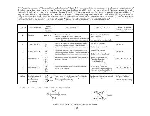
318. The tabular summary <strong>of</strong> "<strong>Compass</strong> Errors and <strong>Adjustment</strong>s," figure 318, summarizes all the various magnetic conditions in a ship, the types <strong>of</strong><br />
deviation curves they create, the correctors for each effect, and headings on which each corrector is adjusted. Correctors should be applied<br />
symmetrically under all but exceptional conditions (discussed in detail later) and as far away from the compass as possible to preserve uniformity <strong>of</strong><br />
magnetic fields about the compass needle array. Other details <strong>of</strong> corrector procedure are emphasized in chapter VI. Fortunately, each magnetic effect has<br />
a slightly different characteristic curve that makes identification and correction convenient. A complete deviation curve can be analyzed for its different<br />
components and, thus, the necessary corrections anticipated. A method for analyzing such curves is described in chapter V.<br />
Coefficient<br />
Type deviation curve<br />
<strong>Compass</strong><br />
headings <strong>of</strong><br />
maximum<br />
deviation<br />
Causes <strong>of</strong> such errors Corrections for such errors <strong>Magnetic</strong> or compass<br />
headings on which to apply<br />
correctors<br />
A Constant. Same on all.<br />
Human: error in calculations..........................................<br />
Physical: compass, gyro, pelorus alignment...................<br />
<strong>Magnetic</strong>: asymmetrical arrangements <strong>of</strong> horizontal s<strong>of</strong>t<br />
iron ...............................................................<br />
Check methods and calculations<br />
Check alignments<br />
Rare arrangement <strong>of</strong> s<strong>of</strong>t iron rods<br />
Any.<br />
B Semicircular sin ø. 090°<br />
270°<br />
Fore-and-aft component <strong>of</strong> permanent magnetic field....<br />
Induced magnetism in asymmetrical vertical iron<br />
forward or aft <strong>of</strong> compass ..............................................<br />
Fore-and-aft B magnets.<br />
Flinders bar (forward or aft)<br />
090° or 270°.<br />
C Semicircular cos ø. 000°<br />
180°<br />
Athwartship component <strong>of</strong> permanent magnetic field....<br />
Induced magnetism in asymmetrical vertical iron port or<br />
starboard <strong>of</strong> compass....................................................<br />
Athwartship C magnets<br />
Flinders bar (port or starboard)<br />
000° or 180°.<br />
D Quadrantal sin 2ø.<br />
045°<br />
135°<br />
225°<br />
315°<br />
Induced magnetism in all symmetrical arrangements <strong>of</strong><br />
horizontal s<strong>of</strong>t iron.<br />
Spheres on appropriate axis.<br />
(athwartship for +D)<br />
(fore and aft for -D)<br />
See sketch a<br />
045°, 135°, 225°, or 315°.<br />
E Quadrantal cos 2ø.<br />
000°<br />
090°<br />
180°<br />
270°<br />
Induced magnetism in all asymmetrical arrangements<br />
<strong>of</strong> horizontal s<strong>of</strong>t iron.<br />
Spheres on appropriate axis.<br />
(port forward, starboard aft for +E)<br />
(starboard forward, port aft for -E)<br />
See sketch b<br />
000°, 090°, 180°, or 270°.<br />
Heeling<br />
Oscillations with roll<br />
or pitch.<br />
Deviations with<br />
constant list.<br />
000°<br />
180°<br />
090°<br />
270°<br />
roll<br />
pitch<br />
Change in the horizontal component <strong>of</strong> the induced or<br />
permanent magnetic fields at the compass due to<br />
rolling or pitching <strong>of</strong> the ship<br />
Heeling magnet (must be re-adjusted<br />
for latitude changes)<br />
090° or 270° with dip<br />
needle.<br />
000° or 180° while rolling.<br />
Deviation = A + B sin ø + C cos ø + D sin 2 ø + E cos 2 ø (ø = compass heading)<br />
Figure 318 – Summary <strong>of</strong> <strong>Compass</strong> Errors and <strong>Adjustment</strong>s<br />
13


